Table of Contents
Advertisement
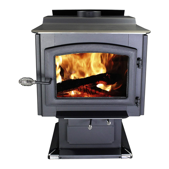
Owner's Instruction and Operation Manual
Model Number:
AW3200E-P
Report Number: F20-586
Tested Per EPA Methods ALT-125, ASTM
E2515, ASTM E3053 and CSA B415
Certified to UL 1482-2011 (R2015) and
ULC-S627-00-REV1
Approved for mobile home installation
in (USA ONLY)
* All Pictures In This Manual Are For Illustrative Purposes Only. Actual Product May Vary.
Save These Instructions In A Safe Place For Future Reference.
SAFETY NOTICE: If this heater is not properly installed, a house fire may result.
For your safety, follow the installation instructions. Never use make-shift
compromises during the installation of this heater. Contact local building or
fire officials about permits, restrictions and installation requirements in your
area. NEVER OPERATE THIS PRODUCT WHILE UNATTENDED.
CAUTION! Please read this entire manual before you install or use your new room
heater. Failure to follow instructions may result in property damage, bodily injury,
or even death. Improper Installation Will Void Your Warranty!
U.S. Environmental Protection Agency
Certified to comply with 2020 particulate
emissions standards.
THIS MANUAL IS SUBJECT TO CHANGE WITHOUT NOTICE.
© 2021 United States Stove Company, 227 Industrial Park Rd., South Pittsburg, TN 37380
R
CALIFORNIA PROPOSITION 65 WARNING:
This product can expose you to chemicals including carbon
monoxide, which is known to the State of California to cause
cancer, birth defects, and/or other reproductive harm. For
more information, go to
853748E-1805K
www.P65warnings.ca.gov
Ph. 800-750-2723
Advertisement
Table of Contents

Related Manuals for Ashley AW3200E-P


Summary of Contents for Ashley AW3200E-P
- Page 1 Owner’s Instruction and Operation Manual Model Number: AW3200E-P Report Number: F20-586 Tested Per EPA Methods ALT-125, ASTM E2515, ASTM E3053 and CSA B415 Certified to UL 1482-2011 (R2015) and ULC-S627-00-REV1 Approved for mobile home installation in (USA ONLY) * All Pictures In This Manual Are For Illustrative Purposes Only. Actual Product May Vary.
- Page 2 The instructions pertaining to the installation of your wood stove comply with UL-1482 (R2015) and ULC-S627 standards. This manual describes the installation and operation of the Ashley, AW3200E wood heater. This heater meets the 2020 U.S. Environmental Protection Agency’s cordwood emission limits for wood heaters sold after May 15, 2020.
-
Page 3: Installation Checklist
INSTALLATION CHECKLIST Your Wood Stove should be installed by a qualified installer only. An NFI qualified Installer can be found at www.nficertified.org/public/find-an-nfi-pro/ CUSTOMER SERVICE 1-800-750-2723 ext 5050 Text to 423-301-5624 Email to: Customerservice@usstove.com COMMISSIONING CHECKLIST This Checklist is to be completed in full by the qualified person who installs this unit. Keep this page for future reference. -
Page 4: Blower Assembly
ASSEMBLY INSTRUCTIONS For Customer Service Call: 800-750-2723 Ext 5050 BLOWER ASSEMBLY PEDESTAL BASE ASSEMBLY The blower assembly must be disconnected from Assemble the pedestal base skirting. Attach the source of electrical supply before attempting two corner pieces (A) to the center section (B) the installation. -
Page 5: Installation
ASSEMBLY INSTRUCTIONS FIREBRICK CONFIGURATION 3. Slide the U-shaped skirting assembly around the pedestal base and secure with two 1/4” long Replace the Firebrick as shown in the illustration. pan head sheet metal screws at the rear corners. INSTALLATION SAFETY NOTICE •... -
Page 6: Floor Protector
INSTALLATION FLOOR PROTECTOR • To reduce flue clearances from combustible materials, contact your local safety department. This heater must have a non-combustible floor protector with an R-Value of at least 1.2 installed beneath it if the floor is constructed of combustible material. -
Page 7: Chimney Connector (Stove Pipe)
INSTALLATION 6. A ventilation system is installed in the house. with 8 GA copper wire using a serrated or star washer to penetrate paint or protective coating to ensure grounding. CHIMNEY CONNECTOR (STOVE PIPE) Install crimped 1/4” slope per foot towards stove. -
Page 8: Importance Of Proper Draft
INSTALLATION IMPORTANCE OF PROPER DRAFT It must rise above the roof at least 3’ (0.9m) from the uppermost point of contact. Draft is a force that moves air from the appliance up through the chimney. The amount of draft 2. The chimney must exceed any part of the in your chimney depends on the length of the building or other obstruction within a 10’... -
Page 9: Masonry Chimney
INSTALLATION COMBUSTIBLE WALL CHIMNEY When a metal prefabricated chimney is used, the manufacturer’s installation instructions must be CONNECTOR PASS-THROUGHS followed. You must also purchase (from the same METHOD - 12” (304.8 mm) Clearance to manufacturer) and install the ceiling support Combustible Wall Member: Using a minimum package or wall pass-through and “T”... - Page 10 INSTALLATION METHOD D - 2” (50.8 mm) Clearance to Combustible Wall Member: Start with a solid-pak listed factory built chimney section at least 12” (304 mm) long, with insulation of 1” (25.4 mm) or more, and an inside diameter of 8” (2 inches [51 mm] larger than the 6”...
- Page 11 OPERATION INSTRUCTIONS NEVER OPERATE THIS PRODUCT WHILE UNATTENDED OPERATING SAFETY PRECAUTIONS CAUTIONS: HOUSE FIRE HAZARDS • NEVER OVERFIRE THIS APPLIANCE BY • DO STORE WOOD FLOOR BUILDING EXCESSIVELY HOT FIRES AS A PROTECTOR, UNDERNEATH STOVEPIPE(S) HOUSE/BUILDING FIRE MAY RESULT. YOU OR ANYWHERE WITHIN CLEARANCES TO ARE OVERFIRING THE APPLIANCE IF IT COMBUSTIBLE SURFACES SPECIFIED FOR...
-
Page 12: Testing Your Wood
OPERATION INSTRUCTIONS wax, and similar substances to start a fire in an temperature never rises higher than 475 °F (246 affected wood heater. °C) on a magnetic thermometer for installation on single wall stove pipes. The thermometer should be Burning these materials may result in the release placed about 18”... -
Page 13: Fueling Instructions
OPERATION INSTRUCTIONS option for efficient heating. A lower burn rate slows 6.5 lbs the flow of usable heat out of the home through the chimney, and it also consumes less wood. NOTICE INITIAL BURNS TO CURE PAINT BECAUSE OF HIGH OPERATING TEMPERATURES, THIS APPLIANCE IS COATED WITH A SPECIAL HIGH TEMP PAINT WHICH REQUIRES A SERIES OF LOW TO MEDIUM BURNS TO FULLY CURE FOR... - Page 14 OPERATION INSTRUCTIONS and set the primary airslide halfway closed. At the WARNINGS: 15 minute point of loading your fuel, the primary • NEVER OVERFIRE YOUR STOVE. IF ANY air slide should be set at the low setting which is PART OF THE STOVE STARTS TO GLOW RED, pulling the airslide completely out toward you.
-
Page 15: Chimney Maintenance
CHIMNEY MAINTENANCE NEVER OPERATE THIS PRODUCT WHILE UNATTENDED • Leave the air control fully open for about 5 min. CAUTION: every time you reload the stove to bring it back DO NOT OVERFIRE APPLIANCE. YOU ARE to proper operating temperatures. The secondary OVERFIRING IF ANY PART OF THE APPLIANCE combustion can only take place if the firebox is GLOWS RED. -
Page 16: Glass Care
CHIMNEY MAINTENANCE SMOKE & CO MONITORS replacing it. When replacing the glass, you should change the glass gasket to make sure you keep it Burning wood naturally produces smoke and sealed. carbon monoxide(CO) emissions. CO is a poisonous gas when exposed to elevated concentrations for •... -
Page 17: Repair Parts
REPAIR PARTS Part # Description 40597 Skirt Corner 892268 Heat Shield (Left) 26546 Front Skirt 892269 Heat Shield (Rear) 26553 Right Side Skirt 892267 Heat Shield (Right) 69911 Pedestal 892278 Top Trim To order parts: 892279 Hearth Trim Call 1-800-750-2723 Ext 5051 or 69912 Ash Drawer Email to: parts@usstove.com... - Page 18 REPAIR PARTS Part # Description 88194 C-Cast Bottom 892280 Notched Firebrick 891414 Half Firebrick 89066 Firebrick (4-1/2 X 9) 892281 1.5” Firebrick 40595 Half Brick Ash Plug 86698 Tube(1), Secondary Air Tube (4mm) 86699 Tube(2,3), Secondary Air Tube (3mm) 86700 Tube(4), Secondary Air Tube (2.5mm) 86701 Tube(5), Secondary Air Tube (2.0mm)
-
Page 19: Wiring Diagram
WIRING DIAGRAM DANGER: SHOCK HAZARD. DISCONNECT POWER SOURCE BEFORE INSTALLATION AND WHENEVER SERVICING BLOWER ASSEMBLY. CAUTION: MOVING PARTS CAN CAUSE INJURY. DO NOT OPERATE WITH COVER REMOVED. Black White Black Black Black Black Blower Blower Rheostat Motor Blower Specs: Attach Ground 110, 60 Hz AC, Green White... -
Page 20: Service Record
SERVICE RECORD It is recommended that your heating system is serviced regularly and that the appropriate Service Interval Record is completed. SERVICE PROVIDER Before completing the appropriate Service Record below, please ensure you have carried out the service as described in the manufacturer’s instructions. Always use the manufacturer's specified spare part when replacement is necessary.
Need help?
Do you have a question about the AW3200E-P and is the answer not in the manual?
Questions and answers
Is there a diagram of the internal working parts for the primary & secondary air draft controls Also, should the ash plug be removed during use or just when cleaning?
The provided context does not mention a diagram of the internal working parts for the Ashley AW3200E-P primary and secondary air draft controls. Additionally, it does not specify whether the ash plug should be removed during use or only when cleaning.
This answer is automatically generated