Table of Contents
Advertisement
Quick Links
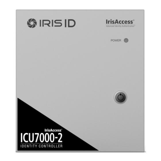
ICU7000-2
HARDWARE GUIDE
I D E N T I T Y
C O N T R O L L E R
VERSION 1.0
CONTROLS UP TO
2 iCAMs
• Supports all iCAM7 series Camera Units
• iCAM4000 series Support Available
• Easy Installation
• Surface Mount Installation
Packing List
What's in the Box
• ICU7000-2 - Identity Controller Unit
• Power Adapter
Input: 100-240VAC @ 1.0AMP 50/60Hz
Output: 12VDC - 2.5AMPS
• Power Cable (110 VDC)
• Grommet
• Keys (x2)
• Hardware Guide
Required Equipment (not included)
Hardware Components
• iCAM7 series Camera unit (sold separately)
• Windows Compatible computer (Refer to the iData
EAC Software Manual for details)
Network
• Ethernet Switch (an Ethernet Hub is not acceptable)
• Ethernet Wiring - CAT5e or better with RJ45 connectors
Software
• iData EAC Software version 3.11.x or above (Refer to the iData EAC Software Manual for details)
Power Source (optional)
• External power source - 12-24 VDC +/- 10% / Minimum 24W (12VDC @ 2AMPS)
(Measured at ICU7000-2 unit)
• Uninterruptible Power Supply (strongly recommended)
EASY
INSTALLATION
ICU7000-2
Advertisement
Table of Contents

Subscribe to Our Youtube Channel
Summary of Contents for IRIS ID IrisAcces ICU7000-2
- Page 1 ICU7000-2 HARDWARE GUIDE I D E N T I T Y C O N T R O L L E R VERSION 1.0 CONTROLS UP TO EASY ICU7000-2 2 iCAMs INSTALLATION • Supports all iCAM7 series Camera Units • iCAM4000 series Support Available •...
-
Page 2: Hardware Information
Hardware Information Cable Channel Knock-out Top View Power Light Indicator Front View Case Lock Bottom View Cable Channel Knock-out Air Vent Side View Model Serial Number Label... - Page 3 Inside ICU7000-2 Inside RTC Battery Speaker Wiring Legend Power LED Indicator Guide Factory Default Button On/Off Switch Tamper Switch Input / Output Ethernet Connection Connections (Channel 1) Power Connection Cable Channel Knock-out Input / Output Connections (Channel 2) Inside the ICU7000-2 Installation Guidelines •...
-
Page 4: Installation
General Wiring Requirements The ICU7000-2 unit requires at least the following wires: Ethernet network wiring to connect with the network switch for communication. For systems consisting of only the ICU and an iCAM, an Ethernet cross-over cable NOTE may be used. IMPORTANT: IT IS RECOMMENDED THAT THE IRISACCESS SYSTEM BE PLACED ON A PRIVATE NETWORK SEPARATE FROM GENERAL CORPORATE OR PUBLIC ACCESS. -
Page 5: Power Connection
7. Mount the enclosure on the wall using appropriate hardware. The ICU7000-2 is designed for surface mounting only. NOTE Power Connection • The included power adapter is auto switching from 110VAC~240VAC 50/60Hz and includes an IEC60320 C13 to NEMA 5 mains power cable. •... - Page 6 Wire Connection Details External GPIO GPIO Specifications: • For output, the GPIO can provide 5VDC @ 20mA. • For Input, the GPIO is selectable between active High & active Low. • Assignment of GPIO is handled through Software External GPIO...
- Page 7 RS232 Output RS232 serial communication port for connection with an access panel or to other computer equipment. When configured, the Card ID associated with the user is output from the RS232 output port upon a successful identification. To RS232 port of computer or access system RS232...
-
Page 8: Relay Output
Relay Output IMPORTANT: ONLY KNOWLEDGEABLE PROFESSIONAL INSTALLERS SHOULD BE USED TO INSTALL ALL ELECTRONIC ENTRY/EXIT LOCKING DEVICES. DIRECT CONNECTION OF ELECTRONIC ENTRY/EXIT LOCKING DEVICES SHOULDN’T BE MADE FROM THE RELAY OUTPUTS ON THE ICAM. IT IS THE RESPONSIBILITY OF THE INSTALLER TO ASSURE THAT THE INSTALLATION IS PERFORMED IN ACCORDANCE WITH ALL COUNTRY/STATE/ LOCAL FIRE AND SAFETY REGULATIONS AND THAT ANY 3RD PARTY PRODUCTS USED WILL NOT CREATE A HAZARD. -
Page 9: Wiegand Input
Wiegand Input Wiegand input is available on the iCAM for connection from 3rd party proximity card readers. This connection can provide 12VDC and a maximum 300mA current to a proximity card reader. Wiegand Intput External Prox Card 12VDC Reader DATA_0 DATA_1 GROUND External Speaker Out... - Page 10 ICU Configuration The ICU7000-2 contains a configuration interface called the ICU7000-2 Configuration. This configuration interface allows the installer to setup the ICU’s IP Address, IrisServer connection, and iCAM connection, and other configuration options. How to access the ICU7000-2 Configuration interface From a PC with an internet browser connected to the network (that the ICU7000-2 unit is connected to), type the IP address of the ICU7000-2.
- Page 11 Reset all settings and reload software • Power Unit OFF • Press and Hold the Factory Default Button (FDB) • While still holding the FDB, Turn ON the unit power • Keep the FDB held in for at least 10 seconds. •...
-
Page 12: General Information
Additional information and technical assistance is available on the Iris ID support web site at www.irisid.com/supportservices formerly Iris ID Systems, Inc. 7 Clarke Drive, Cranbury, NJ 08512, USA Tel. 609-819-IRIS(4747) Fax. 609-819-4736 www.irisid.com Printed in Korea ©2015 Iris ID, Inc. All rights reserved. Design and specification subject to change without notice.
Need help?
Do you have a question about the IrisAcces ICU7000-2 and is the answer not in the manual?
Questions and answers