
Related Manuals for ProSoft Technology ILX69-PBS


Summary of Contents for ProSoft Technology ILX69-PBS
- Page 1 ILX69-PBS CompactLogix or MicroLogix Platform PROFIBUS Slave Communication Module April 27, 2016 USER MANUAL...
- Page 2 April 27, 2016 ® ProSoft Technology , is a registered copyright of ProSoft Technology, Inc. All other brand or product names are or may be trademarks of, and are used to identify products and services of, their respective owners. ®...
- Page 3 2.3.2 Communication Stop During Firmware Update ............12 Safety Instructions to Avoid Property Damage ............12 2.4.1 Device Destruction if ILX69-PBS is Installed to Powered PLC ....... 13 2.4.2 Device Destruction by Exceeding Allowed Supply Voltage ........13 2.4.3 Device Destruction by Exceeding Allowed Signaling Voltage......... 13 2.4.4...
- Page 4 Contents ILX69-PBS ♦ CompactLogix or MicroLogix Platform User Manual PROFIBUS Slave Communication Module Configuration and Start-Up Creating the Module in an RSLogix 5000 Project........... 27 5.1.1 Creating a Module in the Project Using an Add-On Profile ........28 5.1.2 Manually Creating a Module in the Project ............. 35 5.1.3...
- Page 5 ILX69-PBS ♦ CompactLogix or MicroLogix Platform Contents PROFIBUS Slave Communication Module User Manual References ......................95 Glossary ........................96 Support, Service & Warranty 10.1 Contacting Technical Support ................. 99 10.2 Warranty Information ..................... 100 Index ProSoft Technology, Inc. Page 5 of 102...
- Page 6 Contents ILX69-PBS ♦ CompactLogix or MicroLogix Platform User Manual PROFIBUS Slave Communication Module Page 6 of 102 ProSoft Technology, Inc. April 27, 2016...
- Page 7 I/O process data image using CompactLogix™ backplane technology. The diagnostics of the ILX69-PBS can be done using the CompactLogix™ PLC program, via the ProSoft web pages or by help of the master configuration and diagnostics software.
- Page 8 Contents ILX69-PBS ♦ CompactLogix or MicroLogix Platform User Manual PROFIBUS Slave Communication Module Reference Systems The firmware of the ILX69-PBS was developed and tested with the following CompactLogix™ controller types and firmware revisions. CompactLogix System Controller Firmware CompactLogix™ 1769-L23 V17.05 CompactLogix™...
- Page 9 PROFIBUS Slave Communication Module User Manual Requirements 1.5.1 Software Requirements The software requirements for using the ILX69-PBS within a CompactLogix™ system are listed below. You must have the following software installed on your PC unless otherwise noted: CompactLogix System ...
- Page 10 Contents ILX69-PBS ♦ CompactLogix or MicroLogix Platform User Manual PROFIBUS Slave Communication Module Page 10 of 102 ProSoft Technology, Inc. April 27, 2016...
- Page 11 Technical knowledge is presumed. The user must assure that all legal regulations are obeyed. Personnel Qualification The ILX69-PBS must only be installed, configured, and removed by qualified personnel. Job-specific technical skills for people professionally working with electricity must be present concerning the following topics: ...
- Page 12 More firmware update information is located at Firmware Update. Safety Instructions to Avoid Property Damage To avoid system damage and device destruction to the ILX69-PBS, you necessarily must read, understand and follow the following safety instructions and safety messages in this manual before you install and operate the ILX69-PBS.
- Page 13 Shut off the power supply of the PLC, before you install the ILX69-PBS module. 2.4.2 Device Destruction by Exceeding Allowed Supply Voltage To avoid device destruction due to high supply voltage to the ILX69-PBS, you must observe the following instructions.
- Page 14 Contents ILX69-PBS ♦ CompactLogix or MicroLogix Platform User Manual PROFIBUS Slave Communication Module Labeling of Safety Messages The Safety Messages at the beginning of a chapter are pinpointed particularly and highlighted by a signal word according to the degree of endangerment. The type of danger is specified by the safety message text and optionally by a specific safety sign.
- Page 15 ILX69-PBS ♦ CompactLogix or MicroLogix Platform Contents PROFIBUS Slave Communication Module User Manual Safety References [S1] ANSI Z535.6-2006 American National Standard for Product Safety Information in Product Manuals, Instructions, and Other Collateral Materials [S2] IEC 60950-1, Information technology equipment - Safety - Part 1: General requirements, (IEC 60950-1:2005, modified);...
- Page 16 Contents ILX69-PBS ♦ CompactLogix or MicroLogix Platform User Manual PROFIBUS Slave Communication Module Page 16 of 102 ProSoft Technology, Inc. April 27, 2016...
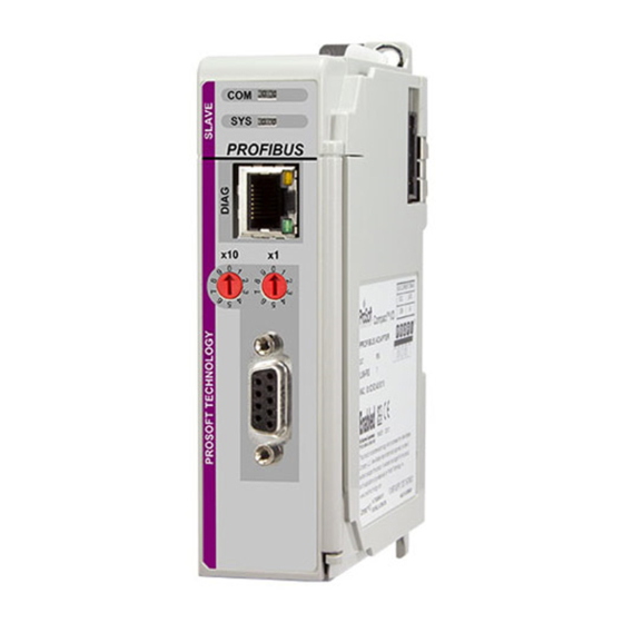
- Page 17 ILX69-PBS ♦ CompactLogix or MicroLogix Platform Contents PROFIBUS Slave Communication Module User Manual About the ILX69-PBS In This Chapter Device Drawing ILX69-PBS ..............17 PROFIBUS Interface................18 Ethernet Interface ..................20 Removable Memory Card ..............21 Power Supply ..................21 Device Drawing ILX69-PBS ProSoft Technology, Inc.
- Page 18 Contents ILX69-PBS ♦ CompactLogix or MicroLogix Platform User Manual PROFIBUS Slave Communication Module PROFIBUS Interface PROFIBUS Interface (D-Sub female connector, 9 pin): Connection with D- Signal Description Sub female connector RxD / TxD-P Receive/Send Data-P, respectively connection B plug CNTR-P...
- Page 19 PROFIBUS Slave Communication Module User Manual If the ILX69-PBS is linked with only one other device on the bus, both devices must be connected to the ends of the bus line. These devices must deliver the supply voltage for the termination resistors.
- Page 20 Contents ILX69-PBS ♦ CompactLogix or MicroLogix Platform User Manual PROFIBUS Slave Communication Module Ethernet Interface The Ethernet cable should contain an RJ45 connector. It should have a twisted pair cable of category 5 (CAT5) or higher, which consists of 4 twisted cores and has a maximum transmission rate of 100 MBit/s (CAT5).
- Page 21 ILX69-PBS ♦ CompactLogix or MicroLogix Platform Contents PROFIBUS Slave Communication Module User Manual 3.3.2 Ethernet Connection Data Medium 2 x 2 Twisted-pair copper cable, CAT5 (100 MBit/s) or better Length of cable Maximum 100 m Transmission rate 10 MBit/s / 100 MBit/s...
- Page 22 Contents ILX69-PBS ♦ CompactLogix or MicroLogix Platform User Manual PROFIBUS Slave Communication Module Page 22 of 102 ProSoft Technology, Inc. April 27, 2016...
- Page 23 Issues for the Network Conception The ILX69-PBS has address rotary switches to set an station address from 0 to 99. If set to 0, address will be taken from the configuration assembly. Using the PLCs configuration data, an address range from 0 to 125 is adjustable.
- Page 24 Move the ILX69-PBS back along the tongue-and-groove slots until the bus connectors line up with each other. Move the ILX69-PBS bus lever fully to the left until it clicks. Ensure it is locked firmly in place. Attach and lock an end cap terminator to the ILX69-PBS by using the tongue-and-groove slots as before.
- Page 25 Shut off the power of the Rockwell CompactLogix™ controller. Discharge yourself. Unlock the end cap bus terminator. Remove the end cap terminator from the ILX69-PBS by using the tongue-and-groove slots. Move the ILX69-PBS bus lever in the unlocked (fully right) position.
- Page 26 Contents ILX69-PBS ♦ CompactLogix or MicroLogix Platform User Manual PROFIBUS Slave Communication Module Page 26 of 102 ProSoft Technology, Inc. April 27, 2016...
- Page 27 The slave module can use this configuration during startup. Creating the data objects and the ladder diagram in Studio 5000/RSLogix 5000. Creating the Module in an RSLogix 5000 Project In an RSLogix 5000 project, there are two ways you can add the ILX69-PBS module to the project. ...
- Page 28 Contents ILX69-PBS ♦ CompactLogix or MicroLogix Platform User Manual PROFIBUS Slave Communication Module 5.1.1 Creating a Module in the Project Using an Add-On Profile Installing an Add-On Profile Download the MPSetup.exe file from the product web page (found at http://www.prosoft-technology.com) or from the ProSoft Solutions DVD onto the local hard drive.
- Page 29 ILX69-PBS ♦ CompactLogix or MicroLogix Platform Contents PROFIBUS Slave Communication Module User Manual Continue to follow the steps in the wizard to complete the installation. ProSoft Technology, Inc. Page 29 of 102 April 27, 2016...
- Page 30 Contents ILX69-PBS ♦ CompactLogix or MicroLogix Platform User Manual PROFIBUS Slave Communication Module Click F when complete. The AOP is now installed in RSLogix 5000. You do not INISH need to reboot the PC. Page 30 of 102 ProSoft Technology, Inc.
- Page 31 ILX69-PBS ♦ CompactLogix or MicroLogix Platform Contents PROFIBUS Slave Communication Module User Manual Using an Add-On Profile In RSLogix 5000, expand the I/O C folder in the Project tree. Right-click ONFIGURATION the appropriate communications bus and choose N ODULE This opens the Select Module Type dialog box. In the Module Type Vendor Filters area, uncheck all boxes except the P box.
- Page 32 Contents ILX69-PBS ♦ CompactLogix or MicroLogix Platform User Manual PROFIBUS Slave Communication Module Select the ILX69-PBS module in the list and click C REATE Page 32 of 102 ProSoft Technology, Inc. April 27, 2016...
- Page 33 ILX69-PBS ♦ CompactLogix or MicroLogix Platform Contents PROFIBUS Slave Communication Module User Manual A New Module dialog box opens. In the G tab, enter "ILX69PBS" in the N ENERAL field and the appropriate S for the module. Click on the C tab (Offline).
- Page 34 In most applications, O is sufficient. With this option, the BTAIN FROM ASTER configuration is done within the PROFIBUS master software and sent to the ILX69-PBS. The O option is a unique option that allows the CompactLogix BTAIN FROM ADDER controller to "lock"...
- Page 35 PROFIBUS Slave Communication Module User Manual 5.1.2 Manually Creating a Module in the Project This section covers the manual configuration of the ILX69-PBS in a CompactLogix™ system. When complete, please see Configuration by Controller Application 46 for module- specific configuration parameters.
- Page 36 Contents ILX69-PBS ♦ CompactLogix or MicroLogix Platform User Manual PROFIBUS Slave Communication Module Select New Module from the context menu as shown below. The following dialog box appears. Select "1769-MODULE Generic 1769 module" and click OK. The Module Properties dialog will open.
- Page 37 ILX69-PBS ♦ CompactLogix or MicroLogix Platform Contents PROFIBUS Slave Communication Module User Manual Module Properties 1 The communications parameters for the module should be set as shown in the dialog below. Enter PBS as the N and enter a short description for the module.
- Page 38 Contents ILX69-PBS ♦ CompactLogix or MicroLogix Platform User Manual PROFIBUS Slave Communication Module Module Properties 2 The Requested Packet Interval RPI is shown in the following dialog. Within this time interval, the I/O data between module and controller are exchanged.
- Page 39 ILX69-PBS ♦ CompactLogix or MicroLogix Platform Contents PROFIBUS Slave Communication Module User Manual 5.1.3 Importing the Ladder Rung In the Controller Organization window, expand the T folder and subfolder until you ASKS reach the M folder. ROGRAM In the M folder, double-click to open the M ladder.
- Page 40 This action opens the Import Configuration dialog box, showing the controller tags that will be created. Verify that the slot number is correct for the module in the Local:x tags. This must match the physical slot number location of the ILX69-PBS in the CompactLogix™ bus. Page 40 of 102 ProSoft Technology, Inc.
- Page 41 ILX69-PBS ♦ CompactLogix or MicroLogix Platform Contents PROFIBUS Slave Communication Module User Manual Click OK to confirm the import. When the import is completed, the new Add-On Instruction rung will appear in the ladder. The procedure has also imported new user-defined data types, controller tags and the Add-On instruction for your project.
- Page 42 When the AOI is imported into the project, the ILX69-PBS MSG tags reference slot 1 in its path configuration. If the ILX69-PBS is not located in slot 1, you will need to edit the MSG instruction Communication Path to the proper slot number.
- Page 43 ... to open the OMMUNICATION ROWSE Message Path Browser window. In the Message Path Browser window, select the slot location of the ILX69-PBS. The Path field updates when the module is selected. Click OK. ProSoft Technology, Inc. Page 43 of 102...
- Page 44 Contents ILX69-PBS ♦ CompactLogix or MicroLogix Platform User Manual PROFIBUS Slave Communication Module Back In the Message Configuration window, the Path field shows the ILX69-PBS properly in place. Click A , then click OK. PPLY Repeat these steps for each MSG instruction in the ILX69-PBS AOI.
- Page 45 PROFIBUS slave device. The ILX69-PBS GSD file contains the information that is specific to the ILX69-PBS. The ILX69-PBS GSD file is named "PSFT0EE1.GSD". It is located on the ProSoft Solutions DVD. You must provide this file to the PROFIBUS master configuration software. Refer to the master's documentation of how to import GSD files.
- Page 46 PROFIBUS Slave Communication Module 5.2.3 Configuration by Controller Application The second option to configure the ILX69-PBS is through the controller application. If you’re unable to install the AOP due to company policy or other reasons, you will need to manually configure the module through the controller application.
- Page 47 The ILX69-PBS has two rotating address switches to set the network address from 0 to 99. If you need to assign the ILX69-PBS to an address above 99, set both address switches to 0. The module will take the address parameter from the configuration data array.
- Page 48 ILX69-PBS to different locations in its I/O area. The individually configured modules are mapped linearly in the I/O area of the ILX69-PBS. It is possible to configure up to 24 I/O modules. A module is defined by a Module Type and its Module Length:...
- Page 49 SD Card 5.3.1 Start-up Behavior with or without SD Card The start-up behavior of the ILX69-PBS depends on whether an SD memory card is inserted in the module or not. Start-up without Memory Card On power-up, the ILX69-PBS and the firmware are started and the configuration data is loaded from the CompactLogix processor using the Local:x:C.Data array into the ILX69-PBS...
- Page 50 The user does not need to create this file. 5.3.3 Reset Device to Factory Settings with Memory Card Using a memory card that has the basic firmware stored on it, the ILX69-PBS can be restored back to factory settings.
- Page 51 Acyclic Messaging .................60 Studio 5000 PROFIBUS Data Values The ILX69-PBS PROFIBUS network data values (input and output) are located in the Controller Tags of Studio 5000. 6.1.1 PROFIBUS Network Input Data PROFIBUS network Input data is sent from the slave to the Master. This data is stored in the ILX69PBS.PROFIBUSDATA.INPUT array.
- Page 52 The following sections contain the I/O memory mappings of the ILX69-PBS. The I/O area is used for communication status and cyclic I/O data. 6.2.1 I/O Arrays Overview Input Array Below is a summary of the register layout of the input area of the ILX69-PBS. The offset values are defined in bytes. Offset Register Type...
- Page 53 Slave Status Information ExtStatusInfo[96] 136 to 379 PROFIBUS Output Area PBOutputData Output Array Below is a summary of the register layout of the output area of the ILX69-PBS. The offset values are defined in bytes. Offset Register Type Name Device Command Register...
- Page 54 0 = Not ready, 1 = Ready Firmware Revision This data field contains the current Firmware Revision of the ILX69-PBS. The Minor revision is the low byte and the Major revision is the high byte. The mapping is shown below.
- Page 55 A 128 byte Slave Status field is transferred to the user program via the input data area image. It contains the ILX69-PBS status, beginning with byte 8 of the input region. The status information encompasses 32 bytes of static information and 96 bytes bytes reserved for the extended status field.
- Page 56 PROFIBUS master. Example: If the ‘OutputDataLen’ indicates a value of 4 Bytes, then it is related to the input area of the ILX69-PBS, because the input area of the ILX69-PBS are outputs from point of view of a PROFIBUS master. The same relation applies to the status ‘InputDataLen’...
- Page 57 ILX69-PBS. Extended Status Information Via the extended status area, the ILX69-PBS is ready to transfer 96 bytes of extended status information to the controller application. The information transferred depends on the parameter "ExtStaSelect" in the "Device Command Register". This can be controlled by the application program.
- Page 58 Contents ILX69-PBS ♦ CompactLogix or MicroLogix Platform User Manual PROFIBUS Slave Communication Module Extended Status 3: Master Configuration (Length 49 Byte) Structure member Data type Description CfgLength SINT Number of valid configuration bytes CfgByte1 SINT Configuration byte 1 CfgByte2 SINT...
- Page 59 Unexpected Responses from User ILX69-PBS Input Data (PROFIBUS Network Output Data) Starting at byte 136, the remainder of the ILX69-PBS input array is used for the PROFIBUS network output data sent from the master to the ILX69-PBS. The data is then transferred from the ILX69-PBS to the controller via the AOI.
- Page 60 Reserved Reserved ILX69-PBS Output Data (PROFIBUS Network Input Data) Starting at byte 4, the remainder of the ILX69-PBS output array is used for the PROFIBUS network input data to be sent to the master. Acyclic Messaging PROFIBUS DP acyclic services are supported by the Studio 5000 programming tool by means of CIP messages using the "MSG"...
- Page 61 PROFIBUS Slave Communication Module User Manual 6.3.2 Standard Messaging This section contains the description of the Standard Message supported by the ILX69-PBS. DPS Diagnostic Request The Diagnostic Request command can be used by the controller user application to generate a single diagnostic request to a master. The MSG instruction Request/Confirmation format is as follows.
- Page 62 Contents ILX69-PBS ♦ CompactLogix or MicroLogix Platform User Manual PROFIBUS Slave Communication Module The content of abExtDiagData[ ] follows the PROFIBUS decoding of extended diagnostic data. The abExtDiagData[ ] can contain one or more diagnostic blocks. If the content does not follow these rules, the confirmation will be returned with an error.
- Page 63 ILX69-PBS ♦ CompactLogix or MicroLogix Platform Contents PROFIBUS Slave Communication Module User Manual It will use the following Message Instruction configuration: ProSoft Technology, Inc. Page 63 of 102 April 27, 2016...
- Page 64 User Manual PROFIBUS Slave Communication Module 6.3.3 DPV1 Messaging This section describes DPV1 messaging functions supported by the ILX69-PBS. Note: Every DPV1 read or write request must be acknowledged by the PLC application program. Otherwise, the PROFIBUS master shuts down communication for both channels, V0 (cyclic IO data) and V1 (non-cyclic messages).
- Page 65 ILX69-PBS ♦ CompactLogix or MicroLogix Platform Contents PROFIBUS Slave Communication Module User Manual DPV1 Write The DPV1 Class 1 Write Response is used by the slave to reply to a master DPV1 write request. The MSG instruction Request/Response format is as follows.
- Page 66 Contents ILX69-PBS ♦ CompactLogix or MicroLogix Platform User Manual PROFIBUS Slave Communication Module DPV1 Alarm The DPV1 Class 1 Alarm Request is used to indicate a DPV1 Alarm to the master. The MSG instruction Request/Response format is as follows. ILX69PBS.CONTROL.DPV1.Alarm.Request...
- Page 67 ILX69-PBS ♦ CompactLogix or MicroLogix Platform Contents PROFIBUS Slave Communication Module User Manual DPV1 Error Codes Below are the PROFIBUS DPV1 error codes. Error Code 1 Bit 7 Bit 6 Bit 5 Bit 4 Bit 3 Bit 2 Bit 1 Bit 0...
- Page 68 Contents ILX69-PBS ♦ CompactLogix or MicroLogix Platform User Manual PROFIBUS Slave Communication Module 6.3.4 CIP Messaging Error Codes This section includes errors codes and conditions that can occur when using the CIP messaging commands. Your application should be constructed in a manner in which it catches the two possible error cases: ...
- Page 69 ILX69-PBS ♦ CompactLogix or MicroLogix Platform Contents PROFIBUS Slave Communication Module User Manual Extende Meaning Cause Help Status Status FE hex 0000 hex Message Timeout No answer message was received. FF hex 0514 hex General Error Call support Non-specified error...
- Page 70 Contents ILX69-PBS ♦ CompactLogix or MicroLogix Platform User Manual PROFIBUS Slave Communication Module Page 70 of 102 ProSoft Technology, Inc. April 27, 2016...
- Page 71 You can access the ILX69-PBS web pages for general device, diagnostics information, and firmware upgrades. Access to the Web Pages Enter the IP address of the ILX69-PBS in an internet browser to access the homepage. ProSoft Technology, Inc. Page 71 of 102...
- Page 72 Assigned MAC Address address of the device fixed by the manufacturer IP Address IP address of the ILX69-PBS that can be set via the ProSoft fdt Valid IP address Configuration Manager. The IP address must be unique. The IP address 0.0.0.0 indicates that no IP address has been configured yet.
- Page 73 ILX69-PBS ♦ CompactLogix or MicroLogix Platform Contents PROFIBUS Slave Communication Module User Manual Module Status To display the ILX69-PBS status page, click FUNCTIONS > Module Status to access the device status and diagnostics information. Parameter Description Range of Value/Value Configuration State Status Shows whether the ILX69-PBS is configured or not.
- Page 74 Yes, No network communication. Yes: In COMMUNICATION state. The ILX69-PBS exchanges input/output data with at least one slave. No: Not in COMMUNICATION state. The ILX69-PBS does not exchange input/output data with slaves. Running Shows whether the ILX69-PBS has been configured correctly.
- Page 75 ILX69-PBS ♦ CompactLogix or MicroLogix Platform Contents PROFIBUS Slave Communication Module User Manual Network Status To display the ILX69-PBS network status page, click FUNCTIONS > Network Status. This page contains network status and diagnostics information. Parameter Meaning Range of Value/Value...
- Page 76 Contents ILX69-PBS ♦ CompactLogix or MicroLogix Platform User Manual PROFIBUS Slave Communication Module Parameter Meaning Range of Value/Value Error Count This field holds the total number of errors detected since power- 0 to 65535 (rollover possible) up. The protocol stack counts all of errors in this field no matter whether they were network related or caused internally.
- Page 77 To continue the firmware update click Continue with Update. The firmware file prompt displays. Loading invalid or non-ProSoft Technology authorized firmware files could render your module unusable. Only proceed with a firmware update following instructions of ProSoft Technical Support.
- Page 78 Contents ILX69-PBS ♦ CompactLogix or MicroLogix Platform User Manual PROFIBUS Slave Communication Module Click Browse … and enter ‘User name’ = ‘admin’ and ‘Password’ = ‘admin’ to the Authorization window, and then select the firmware file. Click Open. The name of the selected firmware file displays.
- Page 79 ILX69-PBS ♦ CompactLogix or MicroLogix Platform Contents PROFIBUS Slave Communication Module User Manual Click Update Firmware. ProSoft Technology, Inc. Page 79 of 102 April 27, 2016...
- Page 80 Contents ILX69-PBS ♦ CompactLogix or MicroLogix Platform User Manual PROFIBUS Slave Communication Module If the firmware update fails, the page shows an error message: Firmware update error: Invalid device class. Page 80 of 102 ProSoft Technology, Inc. April 27, 2016...
- Page 81 ILX69-PBS ♦ CompactLogix or MicroLogix Platform Contents PROFIBUS Slave Communication Module User Manual If the firmware update is successful, ‘Firmware update OK’ is displays. To complete the update process, click Reset Device. Initiating a device reset causes the device reboot. A reboot will let the device stop all communication immediately.
- Page 82 Contents ILX69-PBS ♦ CompactLogix or MicroLogix Platform User Manual PROFIBUS Slave Communication Module Check the Please confirm you want to reset the device box Click Submit. Page 82 of 102 ProSoft Technology, Inc. April 27, 2016...
- Page 83 ILX69-PBS ♦ CompactLogix or MicroLogix Platform Contents PROFIBUS Slave Communication Module User Manual When complete, the following dialog will display: ProSoft Technology, Inc. Page 83 of 102 April 27, 2016...
- Page 84 Contents ILX69-PBS ♦ CompactLogix or MicroLogix Platform User Manual PROFIBUS Slave Communication Module Hardware LEDs The following section contains LED descriptions for the CompactLogix™ controller and the ILX69-PBS. 7.2.1 CompactLogix LEDs The CompactLogix™ PLC LEDs are described below. Color State Description One or more tasks are running;...
- Page 85 PROFIBUS Slave Communication Module User Manual 7.2.2 ILX69-PBS LEDs The ILX69-PBS LEDs indicate the status information. Each LED has a specific function during Run, configuration download, and error indications. Communication Status The ILX69-PBS PROFIBUS DP COM LED status is described below.
- Page 86 Contents ILX69-PBS ♦ CompactLogix or MicroLogix Platform User Manual PROFIBUS Slave Communication Module Error Sources and Reasons This section describes the typical problems and sources of error that come up while commissioning the ILX69-PBS. Behavior Significance Typical Reason Help CompactLogix™ I/O LED is...
- Page 87 ILX69-PBS ♦ CompactLogix or MicroLogix Platform Contents PROFIBUS Slave Communication Module User Manual Troubleshooting Troubleshooting of the system is done by examining the LEDs on the front panel of the PLC and the LEDs on the front of the module. The following can help with troubleshooting.
- Page 88 Contents ILX69-PBS ♦ CompactLogix or MicroLogix Platform User Manual PROFIBUS Slave Communication Module Page 88 of 102 ProSoft Technology, Inc. April 27, 2016...
- Page 89 ILX69-PBS ♦ CompactLogix or MicroLogix Platform Contents PROFIBUS Slave Communication Module User Manual Technical Data In This Chapter Technical Data - ILX69-PBS ..............89 Technical Data - PROFIBUS ..............92 Technical Data - ILX69-PBS Note: All technical data can be altered without notice.
- Page 90 For UL compliant usage: The device must be used in a pollution degree 2 environment. Device Dimensions (L x W x H) 131.6 x 92.1x 39.3 mm Mounting/Installation Rockwell backplane interface, refer to section ILX69-PBS Hardware Installation (page 23) RoHS Weight 152 g Power supply Supply Voltage +5 VDC ±5 %, refer to section Power Supply for ILX69-...
- Page 91 ILX69-PBS ♦ CompactLogix or MicroLogix Platform Contents PROFIBUS Slave Communication Module User Manual ILX69-PBS Parameter Value Mounting/Installation Rockwell backplane interface, refer to section ILX69-PBS Hardware Installation (page 23) RoHS Weight 152 g UL Certification The device is certified according UL/cUL Class 1 Div 2...
- Page 92 Contents ILX69-PBS ♦ CompactLogix or MicroLogix Platform User Manual PROFIBUS Slave Communication Module Technical Data - PROFIBUS Parameter Description Maximum number of cyclic input data 244 bytes Maximum number of cyclic output data 244 bytes Maximum number of acyclic data (read/write)
- Page 93 ILX69-PBS ♦ CompactLogix or MicroLogix Platform Contents PROFIBUS Slave Communication Module User Manual Annex In This Chapter PROFIBUS Functionality ...............93 Disposal of Electronic Equipment Waste ..........95 References ....................95 Glossary ....................96 PROFIBUS Functionality 9.1.1 DPV0 Services PROFIBUS DPV0 services refer to the cyclic data exchange mechanism between a class 1 master and a slave.
- Page 94 Contents ILX69-PBS ♦ CompactLogix or MicroLogix Platform User Manual PROFIBUS Slave Communication Module Sync and Freeze Sync and Freeze are optional commands and slaves do not need to support them. The slaves must be able to process the Global Control message. With a Freeze command, the master prompts a slave or a group of slaves to "freeze"...
- Page 95 PROFIBUS communications can be started/stopped by using the "NRDY" (NotReady) Bit. When this bit is set, the communication between the ILX69-PBS and all slaves is stopped. All slaves will clear their outputs and the master will be in stop mode. This control bit allows the user program to make a controlled start of the communication with the PROFIBUS network.
- Page 96 Contents ILX69-PBS ♦ CompactLogix or MicroLogix Platform User Manual PROFIBUS Slave Communication Module Glossary Baud rate Data transmission speed of a communication channel or interface. Boot loader Program loading the firmware into the memory of a device in order to be executed.
- Page 97 PROFIBUS Scanner PROFIBUS DP master module ProSoft fdt Configuration Manager FDT/DTM based configuration and diagnostics software by ProSoft Technology, Inc. RJ45 A connector type often used for Ethernet connection. It has been standardized by the Federal Communications Commission of the USA (FCC).
- Page 98 Contents ILX69-PBS ♦ CompactLogix or MicroLogix Platform User Manual PROFIBUS Slave Communication Module Page 98 of 102 ProSoft Technology, Inc. April 27, 2016...
- Page 99 Warranty Information ................100 10.1 Contacting Technical Support ProSoft Technology, Inc. is committed to providing the most efficient and effective support possible. Before calling, please gather the following information to assist in expediting this process: Product Version Number System architecture...
- Page 100 E-mail: brasil@prosoft-technology.com Languages spoken include: Portuguese, English 10.2 Warranty Information For complete details regarding ProSoft Technology’s TERMS & CONDITIONS OF SALE, WARRANTY, SUPPORT, SERVICE AND RETURN MATERIAL AUTHORIZATION INSTRUCTIONS please see the documents on the ProSoft Solutions DVD or go to www.prosoft-technology/legal...
- Page 101 Contacting Technical Support • 99 I/O Communication and Memory Map • 52 Creating a Module in the Project Using an Add-On ILX69-PBS Hardware Installation • 24, 90, 91 Profile • 28 ILX69-PBS Input Data (PROFIBUS Network Output Creating a New Project • 35 Data) •...
- Page 102 Support, Service & Warranty ILX69-PBS ♦ CompactLogix or MicroLogix Platform User Manual PROFIBUS Slave Communication Module Module Type / Module Length • 48 Warranty Information • 100 Watchdog • 94 Network Status • 75 Watchdog Timeout • 48 Number of Valid Configuration Bytes • 48 Web Page •...
Need help?
Do you have a question about the ILX69-PBS and is the answer not in the manual?
Questions and answers