GW Instek GDM-8245 User Manual
Hide thumbs
Also See for GDM-8245:
- Service manual (100 pages) ,
- User manual (15 pages) ,
- Short instruction (9 pages)

Related Manuals for GW Instek GDM-8245


Summary of Contents for GW Instek GDM-8245
- Page 1 Digital Multimeter GDM-8245 USER MANUAL GW INSTEK PART NO. 82DM-82450E01 ISO-9001 CERTIFIED MANUFACTURER...
- Page 2 This manual contains proprietary information, which is protected by copyright. All rights are reserved. No part of this manual may be photocopied, reproduced or translated to another language without prior written consent of the Good Will company. The information in this manual was correct at the time of printing. However, Good Will continues to improve products and reserves the right to change specifications, equipment, and maintenance procedures at any time without notice.
-
Page 3: Table Of Contents
SAFETY INSTRUCTIONS ............ 5 Safety Symbols ............ 5 Safety Guidelines ..........6 GETTING STARTED ............10 GDM-8245 Characteristics ........ 11 Front Panel Overview ........12 Rear Panel Overview ......... 16 Set Up ............... 17 ... - Page 4 GDM-8245 User Manual Specifications ............ 49 Declaration of Conformity ......... 55 INDEX ................56 ...
-
Page 5: Safety Instructions
GDM-8245 in the best possible condition. Safety Symbols These safety symbols may appear in this manual or on the GDM-8245. Warning: Identifies conditions or practices that could result in injury or loss of life. -
Page 6: Safety Guidelines
DC1200V/AC1000V. (Limitations apply, please see the specifications) CAUTION Make sure the current input level does not exceed 20A. Do not place any heavy objects on the GDM-8245. Avoid severe impact or rough handling that leads to damaging the GDM-8245. - Page 7 Temperature: 0°C to 50°C (operation) (Note) EN 61010-1:2001 specifies the pollution degrees and their requirements as follows. The GDM-8245 falls under degree 2. Pollution refers to “addition of foreign matter, solid, liquid, or gaseous (ionized gases), that may produce a reduction of dielectric strength or surface resistivity”.
- Page 8 GDM-8245 User Manual Do not dispose this instrument as unsorted municipal Disposal waste. Please use a separate collection facility or contact the supplier from which this instrument was purchased. Please make sure discarded electrical waste is properly recycled to reduce environmental impact.
- Page 9 SAFETY INSTRUCTIONS Power cord for the United Kingdom When using the GDM-8245 in the United Kingdom, make sure the power cord meets the following safety instructions. NOTE: This lead / appliance must only be wired by competent persons WARNING: THIS APPLIANCE MUST BE EARTHED...
- Page 10 GDM-8245 User Manual ETTING STARTED This chapter describes the GDM-8245 in a nutshell, including its main features as well as its front and rear panels. After going through the panel overview, follow the Power-up sequence before attempting to use the DMM.
-
Page 11: Getting Started
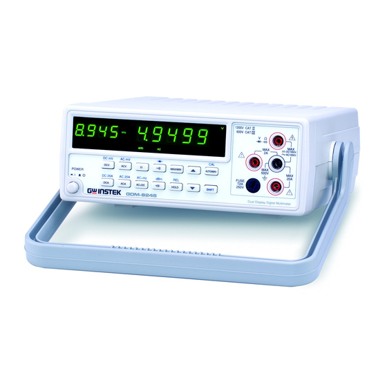
GETTING STARTED GDM-8245 Characteristics The GDM-8245 is a portable, dual-display digital multimeter suitable for a wide range of applications, such as production testing, research, and field verification. High DCV accuracy: 0.03%+4 Performance High current range: 20A High Voltage range: 1000V ... -
Page 12: Front Panel Overview
GDM-8245 User Manual Front Panel Overview Turns On or Off the main Power Switch power. For details about the power up sequence, see page 18. Shows the primary measurement results and parameters. Primary Display Shows the secondary measurement results and Secondary parameters. -
Page 13: Measurement Keys (Upper Row)
GETTING STARTED Accepts DC/AC Current input of up DC/ AC Current to 20A. Input For DCA/ACA details, see page 28. Accepts DC/AC current input less DC/ AC Current than 2A. For details, see page 28. Input (less than 2 A) Measurement keys (Upper row) Measures DC Voltage (page 22). -
Page 14: Measurement Keys (Lower Row)
GDM-8245 User Manual Calibration (page Error! Bookmark SHIFT→ not defined.) AUTO/MAN AUTO/MAN (CAL) Measurement keys (Lower row) Measures DC Current (page 28). Measures DC Current (20A)(page SHIFT → 28). DCA(DC 20A) Measures AC Current (page 28). Measures AC Current (20A)(page SHIFT →... - Page 15 GETTING STARTED The Shift key selects the second SHIFT function assigned to each panel key. When pressed, the indicator appears in the display.
-
Page 16: Rear Panel Overview
GDM-8245 User Manual Rear Panel Overview Accepts the power cord. AC Power Cord 100/120V or 230V; 50/60Hz. Socket For the power on sequence, see page Holds the main fuse: Fuse Socket 100/120V: T0.1A 250V; 230V: T0.08A 250V; For the fuse replacement details, see... -
Page 17: Set Up
GETTING STARTED Set Up Tilt Stand 1. Pull handle base away from the casing. Steps 2. Turn handle into any of the preset positions. Stand Position Carry Position... -
Page 18: Power Up
GDM-8245 User Manual Power Up 1. Ensure that the correct voltage is lined up with the arrow on the fuse cover on the rear panel. 100V 120V 230V 2. Connect the power cord to the AC Voltage input. Steps 2 3 0... - Page 19 GETTING STARTED 4. The display will light up and show the default range of DC 1000V, and auto range. Example: ACV, Auto kH z R M T E RR OR dB m M A X M IN A U T O H O L D R E L S H IF T...
-
Page 20: Basic Measurement
GDM-8245 User Manual ASIC MEASUREMENT Overview Basic Measurement Overview ........ 21 Voltage AC/ AC mV/DC/ DC mV/AC+DC Voltage Measurement ............22 Select Voltage range ..........24 Voltage conversion table ........25 Crest factor table ........... 27 Current DC/ DC 20A / AC/AC 20A/AC+DC Current Measurement ............ -
Page 21: Basic Measurement Overview
BASIC MEASUREMENT Basic Measurement Overview The Basic Measurement chapter refers to the nine types Background of measurements listed below. For advanced measurements, see page 37. DC Voltage Measurement type DCV/DC mV AC Voltage ACV/ AC mV Resistance Ω Diode Continuity DC Current DCA/ DC20A AC Current... -
Page 22: Ac/ Ac Mv/Dc/ Dc Mv/Ac+Dc Voltage Measurement
GDM-8245 User Manual AC/ AC mV/DC/ DC mV/AC+DC Voltage Measurement 0 ~ 1000V Voltage type and range 0 ~ 500mV AC mV 0 ~ 1000V 0 ~ 500mV DC mV 0 ~ 1000V AC+DC* *AC+DC = (AC = true RMS) 1. - Page 23 BASIC MEASUREMENT Connect the test leads between 3. Connect the the V and the COM port. The test lead and display updates the reading. measure When measuring in the maximum range (1000V) range immediately followed by lowest range (500mV), an error Note might occur due to extreme range switching.
-
Page 24: Select Voltage Range
GDM-8245 User Manual Select Voltage range To switch between automatic range and Auto/ Manual manual range, press the AUTO/MAN range key. Press the Up or Down keys to increase or decrease the range. If ACmV or DCmV voltages are selected, the range cannot Note be changed with the Up or Down keys. -
Page 25: Voltage Conversion Table
BASIC MEASUREMENT Voltage conversion table This table shows the relationship between AC, DC, and AC+DC readings for various waveforms. AC-coupled Peak voltages Metered voltage DC and input AC total waveform PK-PK 0-PK AC component **True component only only ac *RMS AC true Sine... - Page 26 GDM-8245 User Manual Triangle 3.464 1.732 0.960 1.000 0.000 1.000 Sawtooth PK-PK *RMS CAL is the displayed value for average responding meters that are calibrated to display RMS for sine waves. √ †K= (D-D2) ††D=X/Y...
-
Page 27: Crest Factor Table
BASIC MEASUREMENT Crest factor table Crest factor is the ratio of the peak amplitude of the signal Background to the RMS value of the signal. It determines the accuracy of AC measurement. If the crest factor of a signal is less than 3.0, voltage measurements will not result in error due to dynamic range limitations at full scale. -
Page 28: Dc/ Dc 20A / Ac/Ac 20A/Ac+Dc Current Measurement
GDM-8245 User Manual DC/ DC 20A / AC/AC 20A/AC+DC Current Measurement 0 ~ 2A Current type 0 ~ 20A DC 20A 0 ~ 2A 0 ~ 20A AC 20A 0 ~ 20A AC+DC *AC +DC = (AC = true RMS) 1. - Page 29 BASIC MEASUREMENT There are two current terminals: MAX 2A and MAX 4. Connect the 20A. The terminal that is used depends on the current. test lead and For current ≤ 2A, use the MAX 2A port, for current up measure to 20A use the MAX 20A port.
-
Page 30: Select Current Range
GDM-8245 User Manual Select Current range To switch between the automatic range Auto/ Manual and the manual range, press the range AUTO/MAN key. Press the Up or Down keys to increase or decrease the range. If AC 20A or DC 20A current ranges are selected, the Note range cannot be changed with the Up or Down keys. -
Page 31: Resistance Measurement
BASIC MEASUREMENT Resistance Measurement Resistance measures how difficult it is for electricity to Background flow between two terminals. Conductance is the reciprocal of Resistance and measures how easily electricity flows. Press Ω key. 1. Activate resistance measurement 2. resistance measurement appears Ω... -
Page 32: Select Resistance Range
GDM-8245 User Manual Select Resistance range To switch between automatic range Auto/MANUAL and manual range, press the range AUTO/MAN key. Press the Up or Down keys to increase or decrease the range. Selection list Range RESOLUTION ACCURACY 0.1%+4 500Ω 0.01Ω... -
Page 33: Diode Test
BASIC MEASUREMENT Diode Test The diode test checks the forward bias characteristics of Background a diode by running a constant forward bias current through the diode. Press the SHIFT key and then press 1. Activate diode )key. test 2. Diode mode display appears +V Indicates Diode test Connect the test lead between the... -
Page 34: Continuity Test
GDM-8245 User Manual Continuity Test Continuity test checks that the resistance in the DUT is Background low enough to be considered continuous (of conductive nature). The built in buzzer sounds when resistance is less than 5 ohms. 3 volts maximum. -
Page 35: Capacitance Measurement
BASIC MEASUREMENT Capacitance Measurement Capacitance measures the amount of electronic charge Background stored between two terminals. Press the key. 1. Activate capacitance measurement 2. Capacitance mode display appears Indicates capacitance measurement AUTO Indicates Automatic range selection − Indicates nanofarads (10 Connect the lead between the V and 3. -
Page 36: Calibration Button
GDM-8245 User Manual Calibration button Calibration button is not supported Background for the end-user. If you need to AUTO/MAN calibrate this device, please contact your distributor for details. -
Page 37: Advanced Measurement
ADVANCED MEASUREMENT DVANCED MEASUREMENT Overview Advanced Measurement Overview ......38 dBm Measurement ..........39 Measure dBm ............39 Max/Min Max/Min Measurement .......... 40 Relative Relative Value Measurement ........41 Hold Hold Measurement ..........42 AC+ Hz AC+Frequency measurement ........43... -
Page 38: Advanced Measurement Overview
GDM-8245 User Manual Advanced Measurement Overview Advanced measurement mainly refers to the type of Background measurement which uses the result obtained by one of the basic measurements: ACV, DCV, ACA, DCA, Resistance, Diode/Continuity, AC+Hz and Capacitance. Before an advanced measurement can be made, a relevant basic measurement mode must first be selected. -
Page 39: Dbm Measurement
ADVANCED MEASUREMENT dBm Measurement Applicable to Using the ACV/AC mV, DCV/ DC mV or AC+DC Background Voltage measurement result, the GDM-8245 calculates the dBm value based on a reference resistance value in the following way. 10 x log (1000 x Vreading... -
Page 40: Max/Min Measurement
GDM-8245 User Manual Max/Min Measurement Applicable to Maximum and Minimum measurement holds the highest Background (maximum) or lowest (minimum) reading for the current measurement. For Max measurement, press the 1. Activate MAX/MIN MAX/MIN key once. Max/Min For Min measurement, press the MAX/MIN key twice. -
Page 41: Relative Value Measurement
ADVANCED MEASUREMENT Relative Value Measurement Applicable to When the REL button is pressed, a reference value is Background measured and stored. All subsequent measurements are displayed as the difference between the reference value and the measured value (delta). The relative function can also be used with the Max/Min mode. -
Page 42: Hold Measurement
GDM-8245 User Manual Hold Measurement Applicable to The HOLD mode can keep the measured value on the Background primary display. Press the HOLD key. 1. Activate Hold measurement 2. Hold measurement display appears HOLD Indicates Hold measurement To cancel the Hold measurement,... -
Page 43: Ac+Hz Measurement
ADVANCED MEASUREMENT AC+Hz Measurement Applicable to The frequency measurement is not affected by the Background MAX/MIN, REL, or Hold mode. In this mode, the reading rate of the DMM may be slower than the normal state. Press the SHIFT key and then press 1. -
Page 44: Faq
Make sure the device is powered on for at least 30 minutes, within +18°C~+28°C. This is necessary to stabilize the unit to match the specifications. If there is still a problem, please contact your local dealer or GW Instek at marketing@goodwill.com.tw. -
Page 45: Appendix
Appendix PPENDIX Fuse Replace the AC source fuse ........46 Replacement Replace input current fuse ........48 Specifications ..........49 Specifications... -
Page 46: Fuse Replacement
GDM-8245 User Manual Fuse Replacement Replace the AC source fuse 1. Remove the power cord. Steps 2 3 0 2. Remove the fuse socket using a flat screwdriver. 2 3 0 3. Replace the fuse in the holder. 2 3 0... - Page 47 Appendix 4. Ensure the correct line voltage is lined up with the arrow on the fuse holder. Insert the fuse socket. 2 3 0 2 3 0 100V/120V T0.1A 250V Rating 230V T0.08A 250V...
- Page 48 GDM-8245 User Manual Replace input current fuse 1. Press the fuse holder with a flat screwdriver. Step 2. Turn anticlockwise. 3. Remove the fuse assembly. Replace the fuse at the end of the holder. T2A, 250V Rating...
- Page 49 Appendix Specifications The specifications are applicable under the following conditions: A 1-year calibration cycle. An operating temperature of 18 to 28˚C (64.4 to 82.4˚C). Relative humidity not exceeding 75%. Accuracy is expressed as ± (percentage of reading + digits). ...
- Page 50 GDM-8245 User Manual TRUE RMS AC, AC+DC VOLTAGE Accuracy Between 2% of range and full range. Range 20Hz- 45Hz- 1kHz- 45Hz 1kHz 2kHz 500mV 1%+15 0.5%+15 0.5%+15 1%+15 0.5%+15 0.5%+15 1%+15 0.5%+15 0.5%+15 500V 1%+15 0.5%+15 -------- 1000V 1%+15 0.5%+15...
- Page 51 Appendix Frequency measurement at ACV range RANGE FREQUENCY INPUT LEVEL ACCURACY (SINE WAVE) ≥120mV 500mV 10Hz ~ 50kHz 0.05%+1 50kHz ~ 150kHz ≥200mV 0.05%+1 ≥1.2V 10Hz ~ 200kHz 0.05%+1 ≥1.2V 20Hz ~ 200kHz 0.05%+1 ≥12V 500V 20Hz ~ 1kHz 0.05%+1 AC+DC measurement does not support AC+Hz function.
- Page 52 GDM-8245 User Manual Crest Factor Range 3.0 at full scale. The burden voltage is the same as the DC current. When the input exceeds the full scale of the selected range, the display will indicate over-range: “—OL—“. FREQUENCY MEASUREMENT AT ACA RANGE...
- Page 53 Appendix Diode check Description Display read forward voltage of diode. Open Voltage 3.1V approx. Maximum Forward 1.5V Voltage Protection 450V dc or peak ac continuous. Continuity Beeper Description Built in buzzer sounds when resistance is less than 5 ohm. Open Voltage 3 volts maximum.
- Page 54 GDM-8245 User Manual Input overload protection FUNCTION RANGE MAXIMUN INPUT 5V~1000V 1000Vdc or peak AC ACV (AC+DC) 5V~1000V 1000V rms continuous & V•Hz maximum DCA,ACA(AC+DC) 500uA~2A fuse protected: T2A 250V DC,AC20A(AC+DC) not fuse protected DC, ACmV (AC+DC) 500mV 450V dc or AC peak...
- Page 55 (2) No. 69, Lu San Road, Suzhou City (Xin Qu), Jiangsu Sheng, China declare, that the below mentioned product Type of Product: Dual Display Digital Multimeter Model Number: GDM-8245 are herewith confirmed to comply with the requirements set out in the Council Directive on the Approximation of the Law of Member States relating to Electromagnetic Compatibility (2004/108/EC) and Low Voltage Directive (2006/95/EC).
- Page 56 GDM-8245 User Manual NDEX Capacitance setting ............... 40 Measurement front panel key ..........14 setting ............... 35 advanced ............38 Characteristics ..........11 Measurement keys ........... 13 Continuity Overview setting ............... 34 measurement ........... 21 Crest factor table ..........27 Power supply safety instructions ....
Need help?
Do you have a question about the GDM-8245 and is the answer not in the manual?
Questions and answers