
Related Manuals for Fluke 87V EX


Summary of Contents for Fluke 87V EX
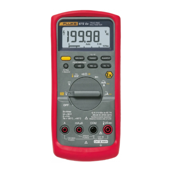
- Page 1 ® 87V EX True-rms Multimeter Calibration Manual April 2006 © 2006 Fluke Corporation, All rights reserved. All product names are trademarks of their respective companies.
- Page 2 Fluke authorized resellers shall extend this warranty on new and unused products to end-user customers only but have no authority to extend a greater or different warranty on behalf of Fluke. Warranty support is available only if product is purchased through a Fluke authorized sales outlet or Buyer has paid the applicable international price.
-
Page 3: Table Of Contents
Table of Contents Title Page Introduction......................1 Contacting Fluke....................1 Precautions and Safety Information..............2 General Safety Information ................2 ATEX Safety Information ................2 Ex-Certification Data..................4 General Specifications ..................5 Detailed Specifications ..................6 AC Voltage Function..................6 DC Voltage, Resistance, and Conductance Function ........ - Page 4 87V EX Calibration Manual Calibration Adjustment Procedure ..............20 Service and Parts....................22...
- Page 5 List of Tables Table Title Page Electrical Symbols ....................5 Approved Batteries....................11 Required Equipment....................13 Display Features..................... 14 Accuracy Tests ....................... 17 Meter Button to Calibration Function ..............20 Calibration Adjustment Steps................. 21 87V EX Final Assembly ..................22...
- Page 6 87V EX Calibration Manual...
- Page 7 List of Figures Figure Title Page Opening the Meter, Battery and Fuse Replacement..........10 Testing the Current Input Fuses ................12 Display Features..................... 14 87V EX Final Assembly ..................23...
- Page 8 87V EX Calibration Manual...
-
Page 9: Introduction
For complete operating instructions, refer to the 87V EX True-rms Multimeter Users Manual. Contacting Fluke To contact Fluke or locate the nearest Service Center, call one of the following telephone numbers: Europe: +31 402-675-200 Or, visit Fluke's Web site at www.fluke.com. -
Page 10: Precautions And Safety Information
87V EX Calibration Manual Precautions and Safety Information In this manual, a Warning identifies conditions and actions that pose hazard(s) to the user; a Caution identifies conditions and actions that may damage the Meter or the test instruments. General Safety Information The Meter complies with: •... - Page 11 “Specifications” section of this manual. • Use only allowed accessories with this Meter in Ex-hazardous areas. See a listing of allowed Fluke accessories at www.Fluke.com. • Avoid using the Meter in aggressive acidic or alkaline solutions. • Do not use the Meter in zone 0.
-
Page 12: Ex-Certification Data
87V EX Calibration Manual • Do not use the Meter if it operates abnormally. Protection may be impaired. When in doubt, have the Meter serviced. • Use only a single 9 volt battery, properly installed in the Meter case, to power the Meter. See “Replacing the Battery” section for instructions and a list of approved batteries. -
Page 13: General Specifications
True-rms Multimeter General Specifications Table 1. Electrical Symbols AC (Alternating Current) Earth ground DC (Direct Current) Fuse Capacitance Diode Battery. Low battery when displayed. Continuity test or continuity beeper tone. Hazardous voltage Double insulated Do not mix with solid waste stream. Risk of Danger. -
Page 14: Detailed Specifications
87V EX Calibration Manual Detailed Specifications For all detailed specifications: Accuracy is given as ±([% of reading] + [number of least significant digits]) at 18 ºC to 28 ºC, with relative humidity up to 90 %, for a period of one year after calibration. -
Page 15: Current Function
True-rms Multimeter Detailed Specifications Current Function [1, 2] Function Range Resolution Accuracy Burden Voltage (typical 60.00 mA 0.01 mA ±(1.0 % + 2) 1.8 mV/mA 400.0 mA 0.1 mA ± (1.0 % + 2) 1.8 mV/mA (45 Hz to 2 kHz) 6.000 A 0.001 A ±... -
Page 16: Electrical Characteristics Of The Terminals
WCaution To avoid damaging the Meter, never apply abrasives, solvents, aromatic hydrocarbons, chlorinated solvents, or methanol- based fluids to the Meter. Periodically wipe the Meter case with Fluke “MeterCleaner ” or a damp cloth and mild detergent. -
Page 17: Opening The Meter Case
True-rms Multimeter Basic Maintenance Dirt or moisture in the A or mA µA input terminals can affect readings and can falsely activate the Input Alert feature without the test leads being inserted. Such contamination may be dislodged by turning the Meter over and, with all test leads removed, gently tapping on the case. -
Page 18: Reassembling The Meter Case
87V EX Calibration Manual aom12f.eps Figure 1. Opening the Meter, Battery and Fuse Replacement Reassembling the Meter Case To reassemble the Meter case: 1. Verify that the rotary knob and circuit board switch are in the OFF position, and that the gasket remains secured to the bottom case. -
Page 19: Replacing The Battery
True-rms Multimeter Basic Maintenance Replacing the Battery Replace the Meter’s 9-volt battery with only approved batteries found in Table 2. XWWarning To avoid false readings, which could lead to possible electric shock or personal injury, replace the battery as soon as the battery indicator (b) appears. - Page 20 87V EX Calibration Manual After replacing the fuse, use the following procedure to verify the integrity of the new fuse and the current circuitry. Refer to Figure 2. 1. Turn the rotary knob to N. 2. To test F2, insert a test lead into the I input terminal and touch the probe to the A input terminal.
-
Page 21: Replacing The Fuses
Equipment Required Characteristics Recommended Model Calibrator AC Voltage Range: 0 - 1000 V ac Fluke 5520A Multi-Product Accuracy: ± 0.12 % Calibrator or equivalent Frequency Range: 60 - 20000 Hz Accuracy: ± 3 % DC Voltage Range: 0 - 1000 V dc Accuracy: ±... -
Page 22: Performance Tests
87V EX Calibration Manual Performance Tests The following performance tests verify the complete operability of the Meter and check the accuracy of each Meter function against the Meter’s specifications. Performance tests should be performed annually to ensure that the Meter is within accuracy specifications. - Page 23 True-rms Multimeter Performance Tests Table 4. Display Features (cont) Number Feature Indication Indicates negative readings. In relative mode, this sign indicates that the present input is less than the stored reference. Indicates the presence of a high voltage input. Appears if the input voltage is 30 V or greater (ac or dc).
- Page 24 87V EX Calibration Manual Table 5. Error Messages Error Messages Replace the battery immediately. bAtt In the capacitance function, too much electrical charge is present on the capacitor diSC being tested. EEPr Invalid EEPROM data. Have Meter serviced. Invalid calibration data. Calibrate Meter.
-
Page 25: Testing The Pushbuttons
True-rms Multimeter Performance Tests Testing the Pushbuttons To test the pushbuttons 1. Turn the Meter rotary knob to J. 2. Press each button and note that the meter responds with a beep for each button press. 3. Press and hold B a second time to exit MIN MAX mode. Testing Meter Accuracy Perform the accuracy test steps in Table 6. - Page 26 87V EX Calibration Manual Table 5. Accuracy Tests (cont.) Test Step Range 5500A Output Display Reading Function 600 Ω 330 Ω ( Use 2 wire Comp) 329.1 to 330.9 Ohms 6 kΩ 3.3 kΩ (Use 2 wire Comp) 3.292 to 3.308 60 kΩ...
-
Page 27: Calibration Adjustment
True-rms Multimeter Calibration Adjustment Table 5. Accuracy Tests (cont.) Test Step Range 5500A Output Display Reading Function 6 V dc 8 Vpp, 2 kHz Sq. Max = 5.896 to 6.104 Wave, DC offset 2 V (87 and 88 only) Min = -1.898 to -2.102 Peak Min/Max 0 °C -1.0 to 1.0... -
Page 28: Calibration Adjustment Password
87V EX Calibration Manual Calibration Adjustment Password WCaution To avoid having to replace the Meter, do not change the calibration password. To start the Calibration Adjustment Procedure, the correct 4-button password must be entered. The password is “1234”. Meter Buttons Used in the Calibration Steps The Meter buttons behave as described in Table 6 when performing the Calibration Adjustment Procedure. - Page 29 True-rms Multimeter Calibration Adjustment If the Meter rotary knob is not in the correct position, or if the measured value is not within the anticipated range of the input value, the Meter emits a double beep and will not continue to the next step. Some adjustment steps take longer to execute than others (10 to 15 seconds).
- Page 30 948609 80BK Thermocouple Assembly, K-Type, Beaded, Molded Dual Banana 1273113 Plug, Coiled Tiltstand of the Ex holster 2520056 87V Ex Users Manual (English, French, & German) 2518115 CD ROM,87V Ex Users Manual 2520777 WTo ensure safety, use exact replacement only.
- Page 31 True-rms Multimeter Service and Parts TL75 Test Lead Set 80BK Alligator Clips AC72 Holster H1-3 MP2-3 Tilt Stand MP6-7 ecg015c.eps Figure 4. 87V EX Final Assembly...
- Page 32 87V EX Calibration Manual...
Need help?
Do you have a question about the 87V EX and is the answer not in the manual?
Questions and answers