Advertisement
Quick Links
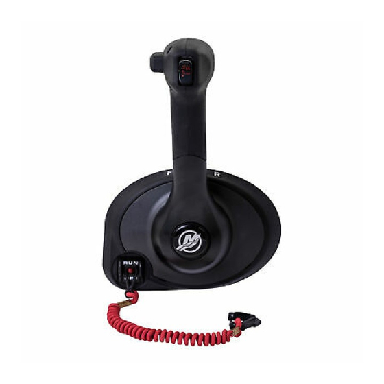
4000 MPC GEN II PISTOL GRIP REMOTE
CONTROL INSTALLATION INSTRUCTIONS
IMPORTANT: This document guides our dealers, boatbuilders, and company service personnel in the proper installation or
service of our products. If you have not been trained in the recommended servicing or installation procedures for these or
similar Mercury Marine products, have the work performed by an authorized Mercury Marine dealer technician. Improper
installation or servicing of the Mercury product could result in damage to the product or personal injury to those installing or
operating the product.
NOTE: After completing installation, place these instructions with the product for the owner's future use.
Pistol Grip Remote Control with Fingertip Neutral Lock Release
Notice to Installer
Throughout this publication, Warnings and Cautions (accompanied by the International Hazard Symbol) are used to alert the
installer to special instructions concerning a particular service or operation that may be hazardous if performed incorrectly or
carelessly. Observe them carefully.
These "Safety Alerts," alone, cannot eliminate the hazards that they signal. Strict compliance to these special instructions
when performing the service, plus common sense operation, are major accident prevention measures.
Indicates a hazardous situation which, if not avoided, could result in death or serious injury.
Indicates a hazardous situation which, if not avoided, could result in minor or moderate injury.
Indicates a situation which, if not avoided, could result in engine or major component failure.
IMPORTANT: Indicates information or instructions that are necessary for a particular step or action.
NOTE: Indicates information that helps in the understanding of a particular step or action.
This instruction sheet has been written and published by the service department of Mercury Marine to aid installers when
installing the products described herein.
90-8M0103111 FEBRUARY 2015
WARNING
!
CAUTION
!
NOTICE
© 2015 Mercury Marine
24953
Page 1 / 22
Advertisement

Related Manuals for Mercury 4000 MPC GEN II


Summary of Contents for Mercury 4000 MPC GEN II
- Page 1 Mercury Marine products, have the work performed by an authorized Mercury Marine dealer technician. Improper installation or servicing of the Mercury product could result in damage to the product or personal injury to those installing or operating the product.
- Page 2 Mercury Marine. Also, that they have been trained in the recommended installation procedures of these products, which includes the use of mechanics’ common hand tools and the special Mercury Marine or recommended tools from other suppliers.
- Page 3 4000 MPC GEN II PISTOL GRIP REMOTE CONTROL INSTALLATION INSTRUCTIONS • Important safety information: The purpose of a lanyard stop switch is to stop the engine when the operator moves far enough away from the operator's position to activate the switch. This would occur if the operator accidentally falls overboard or moves within the boat a sufficient distance from the operator's position.
- Page 4 30.5 cm (12 in.). For applications that require a smaller than the minimum radius, multiple bends or lengths longer than 5.5 m (18 ft), Mercury/Quicksilver GEN II Platinum or Premium cables are required.
- Page 5 4000 MPC GEN II PISTOL GRIP REMOTE CONTROL INSTALLATION INSTRUCTIONS IMPORTANT: Ensure the remote control has a minimum of 45.7 cm (18 in.) straight routing clearance for the control cables and does not contact other components. Refer to the shaded area.
- Page 6 4000 MPC GEN II PISTOL GRIP REMOTE CONTROL INSTALLATION INSTRUCTIONS IMPORTANT: When selecting the mounting area for the panel mount remote control, the area located directly behind the mounting panel must have sufficient clearance for the control module, wiring harness, control cables, and control cable movement.
- Page 7 30.5 cm (12 in.). For applications that require smaller than the minimum radius, multiple bends or lengths longer than 5.5 m (18 ft), Mercury/Quicksilver GEN II Platinum or Premium cables are required.
- Page 8 Mercury and Mariner outboards ‑ standard rotation models, all models through 300 XS with pull throttle, includes 1994‑1/2 20/25 hp Mercury and Mariner outboards ‑ 18 hp, 20 hp, and 25 hp of U.S. origin, with push throttle cable Mercury and Mariner outboards ‑ counterrotation gearcase, all models through 300 XS, unless listed below Mercury and Mariner outboards ‑...
- Page 9 Mercury MerCruiser models standard rotation ‑ The control cable must be installed in the remote control so the cable end will move in the direction of "X" when the shift handle is placed in the forward position.
- Page 10 4000 MPC GEN II PISTOL GRIP REMOTE CONTROL INSTALLATION INSTRUCTIONS Tighten the cable fastener screws to the specified torque. Small spacer Screw Shift cable Throttle cable Large spacer 17555 Tube Ref No. Description Where Used Part No. Loctite 271 Threadlocker...
- Page 11 4000 MPC GEN II PISTOL GRIP REMOTE CONTROL INSTALLATION INSTRUCTIONS Pistol Grip Remote Control with Fingertip Lock Release Installation NOTE: The control handle friction is preset at the factory. To increase or decrease the control handle friction, the adjustment must be made prior to the installation of the remote control module onto the bezel. When adjusting the control handle friction, the control cables must be installed, and the control handle temporarily installed onto the control module to get a true feel for the amount of control handle friction.
- Page 12 4000 MPC GEN II PISTOL GRIP REMOTE CONTROL INSTALLATION INSTRUCTIONS Connect the trim switch connector to the trim motor harness connectors. Lanyard stop switch leads Neutral start safety switch leads Trim switch connection 24970 Install the bushing into the module assembly. Apply a small amount of 2‑4‑C with PTFE to the inside diameter of the bushing.
- Page 13 4000 MPC GEN II PISTOL GRIP REMOTE CONTROL INSTALLATION INSTRUCTIONS Align the tabs on the bezel cover with the slots on the bezel. Snap the bezel cover in place. Bezel Tabs (4) Bezel cover 24971 Apply Loctite 271 Threadlocker on the threads of the control handle retaining screw.
- Page 14 4000 MPC GEN II PISTOL GRIP REMOTE CONTROL INSTALLATION INSTRUCTIONS IMPORTANT: Do not use air driven tools to install the control handle retaining screw. NOTE: As an aid for installing the control handle retaining screw, use the throttle only button as a tool to align the threads to the control.
- Page 15 4000 MPC GEN II PISTOL GRIP REMOTE CONTROL INSTALLATION INSTRUCTIONS WARNING Starting the engine with the drive in gear can cause serious injury or death. Never operate a boat that does not have a neutral‑safety‑protection device. Remote control module assembly neutral start...
-
Page 16: Wire Color Code Abbreviations
Green Orange Pink Purple White Yellow Light Dark Lanyard Stop Switch Wiring Diagrams Mercury/Mariner Outboards 40 HP through 225 (3.0 Liter), Force (1993 and Newer) Neutral start safety leads Bullet or eyelet connectors Ignition key switch YEL/RED YEL/RED YEL/RED YEL/RED... - Page 17 4000 MPC GEN II PISTOL GRIP REMOTE CONTROL INSTALLATION INSTRUCTIONS Mercury MerCruiser All Single Engine Gasoline Models YEL/RED YEL/RED YEL/RED YEL/RED + 1 2 V PPL/WHT PPL/WHT 24977 Neutral start safety leads Bullet or eyelet connectors Ignition key switch Engine harness connector...
- Page 18 4000 MPC GEN II PISTOL GRIP REMOTE CONTROL INSTALLATION INSTRUCTIONS Mercury MerCruiser D1.7L/103, D3.0L/150, D3.6L/180 and D4.2L/220 Diesels BLK (1) TAN/WHT (6) LT BLU (8) GRY (2) BLK (7) WHT/GRN (5) BRN/WHT (10) YEL/RED (7) TAN (3) BRN (4) BLK (8)
- Page 19 4000 MPC GEN II PISTOL GRIP REMOTE CONTROL INSTALLATION INSTRUCTIONS Mercury MerCruiser D7.3L/270 Diesel PUR/WHT PPL/WHT BLK (1) TAN/WHT (6) LT BLU (8) GRY (2) BLK (7) WHT/GRN (5) BRN/WHT (10) YEL/RED (7) TAN (3) BRN (4) BLK (8) BLK/YEL (1)
- Page 20 Cable ends should be manually manipulated to feel for stiffness, binding, or tightness affecting the cable core. Worn, pinched, or corroded cables should be replaced. Mercury/Quicksilver GEN II throttle and shift cables are required for use in this remote control.
- Page 21 4000 MPC GEN II PISTOL GRIP REMOTE CONTROL INSTALLATION INSTRUCTIONS The control module shown on the template is mounted horizontally. Refer to item d. Machine screw drill size Remove the sharp edges on the interior and exterior surfaces Cut out only if equipped with a lanyard stop switch...
- Page 22 4000 MPC GEN II PISTOL GRIP REMOTE CONTROL INSTALLATION INSTRUCTIONS Products of Mercury Marine © MERCURY MARINE. All rights reserved. Reproduction in whole or in part without permission is prohibited. Alpha, Axius, Bravo One, Bravo Two, Bravo Three, Circle M with Waves Logo, K-planes,...
Need help?
Do you have a question about the 4000 MPC GEN II and is the answer not in the manual?
Questions and answers
Can you just order the handle and trim assembly for Mercury MPC 4000 GEN 2 series Mechanical Panel Control