
Related Manuals for Veeder-Root 880-051-1


Summary of Contents for Veeder-Root 880-051-1
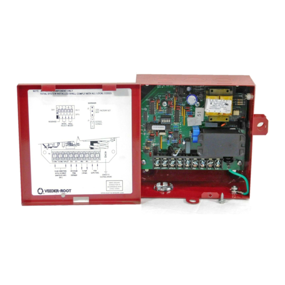
- Page 1 Manual No: 051-330 • Revision: K IQ Control Box Installation and Owner’s Manual Model: 880-051-1 880-052-1 880-058-1 880-059-1...
- Page 2 Notice Veeder-Root makes no warranty of any kind with regard to this publication, including, but not limited to, the implied warranties of merchantability and fitness for a particular purpose. Veeder-Root shall not be liable for errors contained herein or for incidental or consequential damages in connection with the furnishing, performance, or use of this publication.
-
Page 3: Table Of Contents
Table of Contents Introduction Safety Precautions ......................1 Specifications ........................2 IQ Manifold Control Information ..................3 Manifolded PLLD – TLS Decides (multiple hook signals).........4 Manifolded Direct – Unit 1 always turns on first (One shared hook signal) ....4 Manifolded Alternating – The devices alternate turning on first every time the hook signal is disabled. - Page 4 Table of Contents Figures Figure 1. Simple Wiring Configuration Diagrams ...........3 Figure 2. Terminal Block TB1, Models -051, -052 ..........6 Figure 3. -Terminal Block TB1, Models -058, -059 ..........7 Figure 4. Wiring Diagram for Manifolded Systems ..........7 Figure 5. Wiring Diagram for IQ Control Box with TLS-350 Manifolded PLLD Systems ............8 Figure 6.
-
Page 5: Safety Precautions
The microprocessor chip containing software version 3 is marked 805-001C or higher. Appendix A provides application, technical and installation guidelines for Veeder-Root certified technicians who will be installing and setting up the Red Jacket IQ Control Standard Diagnostic Feature with a TLS-450PLUS system. -
Page 6: Specifications
IQ Control Box Installation and Owner’s Manual Specifications WARNING FAILURE TO COMPLY WITH THE FOLLOWING WARNINGS AND SAFETY PRECAUTIONS COULD CAUSE DAMAGE TO PROPERTY, ENVIRONMENT, RESULTING IN SERIOUS INJURY OR DEATH. 1. All installation work must comply with the latest issue of the National Electrical Code (NFPA 70), the Code for Motor Fuel Dispensing Facilities and Repair Garages (NFPA 30A), and any European, national, state, and local code requirements that apply. -
Page 7: Iq Manifold Control Information
IQ Control Box Installation and Owner’s Manual IQ Manifold Control Information IQ Manifold Control Information The main difference between Manifold PLLD, Manifold Direct and Manifold Alternation modes shown in Figure 1 is which IQ Box unit turns on first when there is an active hook signal. Figure 1. -
Page 8: Manifolded Plld - Tls Decides (Multiple Hook Signals)
IQ Control Box Installation and Owner’s Manual IQ Manifold Control Information Manifolded PLLD – TLS Decides (multiple hook signals) Overview In this mode the devices operate while being networked together over RS485 and with a PLLD installation. In this scenario, each IQ box receives a separate hook signal from the TLS. The TLS is then able to turn on the devices with a hook signal to activate a PLLD test. - Page 9 IQ Control Box Installation and Owner’s Manual IQ Manifold Control Information becomes a point where the power drawn by the motor reaches its threshold. At this point the IQ box sends a request for the next device in line to turn on in conjunction with itself. So, in this case Unit 2 will always turn on next.
-
Page 10: Installation And Wiring Instructions
Installation and Wiring Instructions This equipment must be installed in a non-hazardous location. 1. Locate an area that allows all of the wiring to enter through the bottom knockouts of the IQ Control Box. Consider the ability to view the indicator on the side of the base and access to the reset button when choosing a location. -
Page 11: Figure 3. -Terminal Block Tb1, Models -058, -059
IQ Control Box Installation and Owner’s Manual IQ Manifold Control Information Figure 3. -Terminal Block TB1, Models -058, -059 Figure 4. Wiring Diagram for Manifolded Systems... -
Page 12: Figure 5. Wiring Diagram For Iq Control Box With
IQ Control Box Installation and Owner’s Manual IQ Manifold Control Information Figure 5. Wiring Diagram for IQ Control Box with TLS-350 Manifolded PLLD Systems... -
Page 13: Figure 6. Wiring Diagram For Iq Control Box With Tls-450Plus Manifolded Dplld Systems
IQ Control Box Installation and Owner’s Manual IQ Manifold Control Information COM+ COM- SHLD I/O Module TO PUMP 230VAC PUMP OUTPUT IQ2 COM + COM + VR RELAY RS-485 COMMUNICATION CABLE COM - COM+ COM- SHLD TO PUMP PUMP OUTPUT IQ1 230VAC DISPENSER HOOK 330-1.eps... -
Page 14: Determine The Motor Type
IQ Control Box Installation and Owner’s Manual Determine the Motor Type Determine the Motor Type Warning! Disconnect, lock out, an tag power to the IQ Control Box at the panel before starting these steps. Determination of the Motor Type can be accomplished by measuring the resistance readings at the junction box in the STP and comparing to Table 1 or Table 2 below. -
Page 15: Table 2. Electrical Service Information (For Umps Containing A Faradyne Motor With End View B)
IQ Control Box Installation and Owner’s Manual Determine the Motor Type Table 1. Electrical Service Information (for UMPs Containing a Franklin Motor with End View A) Required power supply rating for 60 Hz, 1 phase pumps is 208 - 230 Vac. For 50 Hz, 1 phase pumps, required rating is 220 - 240 Vac. Voltage Fluctuation Range... -
Page 16: Table 3. Ump Model Dimensions
IQ Control Box Installation and Owner’s Manual Determine the Motor Type Table 3 lists UMP weights and lengths and Table 4 lists pump shut off pressures. The weights and lengths listed below are approximate values and will vary due to manufacturing tolerances. -
Page 17: Programming The Motor Type
IQ Control Box Installation and Owner’s Manual Programming the Motor Type Programming the Motor Type Warning! Disconnect, lock out, an tag power to the IQ Control Box at the panel before starting this procedure. 1. Open the IQ Control Box cover. 2. -
Page 18: Table 6. Reset/Cal Button And Led Indicator Actions
IQ Control Box Installation and Owner’s Manual Programming the Motor Type Table 5. Motor Type Programming Switch Position Number of Code LED Manufacturer Motor Flashes 1/3 60 Hz 3/4 60 Hz 1.5 60 Hz 2.0 60 Hz FRANKLIN 3/4 50 Hz 1.5 50 Hz 2.0 50 Hz UNKNOW... -
Page 19: Setup Switch Chart
IQ Control Box Installation and Owner’s Manual Setup Switch Chart 10. The unit must be calibrated every time the Motor Type programming is performed even if the Motor Type does not change. Set the five DIP switches to the desired pump type and mode / role select configuration (see Figure 11). -
Page 20: Initial Calibration
IQ Control Box Installation and Owner’s Manual Initial Calibration Initial Calibration Once all of the wiring is complete and the dip switch and jumpers are set the cover can be attached to the enclosure. Every controller in the system must be calibrated at this time. WARNING! Power to the controller should only be applied when all wiring is con- nected and the cover is installed. -
Page 21: Troubleshooting
Troubleshooting WARNING! If at any time during a troubleshooting procedure the enclosure must be opened, disconnect controller power prior to removal of the cover. The input terminals D1 and D2 are powered from the dispenser which is on a different circuit and may be energized even with the control box power disconnected. -
Page 22: Dry Run
IQ Control Box Installation and Owner’s Manual Description of Fault Conditions WARNING! Before starting this troubleshooting procedure disconnect all electrical power to the controller including the dispenser inputs. Failure to do so may COULD CAUSE DAMAGE TO PROPERTY, ENVIRONMENT, RESULTING IN SERIOUS INJURY OR DEATH. -
Page 23: Appendix A - Tls-450Plus Diagnostic Monitoring Of
TLS-450PLUS Diagnostic Monitoring of Red Jacket IQ Control Boxes Equipment Requirements, Installation and Setup Introduction This Appendix provides application, technical and installation guidelines for Veeder-Root certified technicians who will be installing and setting up the Red Jacket IQ Control Standard Diagnostic Feature with a TLS-450PLUS system. -
Page 24: Table A-1. Tls-450Plus Comm Module Compatibility
Appendix A Determining Number of RS-485 Ports Needed Table A-1. TLS-450PLUS Comm Module Compatibility TLS-450PLUS Console Slot 1 Slot 2 Slot 3 Slot 4 Slot 5 Modules COMM Port Port Port Port Port Port Port Port Port Modules System Type RS-232 Dual RS-232 RS-485... -
Page 25: Installing Rs-485 Wiring Between Iq Control Boxes & Tls-450Plus
Appendix A Installing RS-485 Wiring Between IQ Control Boxes & TLS-450PLUS Installing RS-485 Wiring Between IQ Control Boxes & TLS-450PLUS 6. Prepare a satisfactory length of CAT5 or better 3-wire cable having a RJ-45 connector on one end (connects to TLS-450PLUS and no connector on the end that connects to the IQ Control Box (see Figure A-1). -
Page 26: Upgrading Iq Control Box Software - Repeat For Each Iq Control Box
Appendix A Upgrading IQ Control Box Software - Repeat For Each IQ Control Box Upgrading IQ Control Box Software - Repeat For Each IQ Control Box 1. With power applied to the IQ Control Box, confirm that no dispensing occurs during the next step. 2. -
Page 27: Programming The Motor Type
Appendix A Upgrading IQ Control Box Software - Repeat For Each IQ Control Box 4. Position the small hooks in the ends of the chip removal tool under the ends of U1 as shown in Figure A-4. Rock the tool lengthwise as you pull on the chip to lift it out of socket. 5. -
Page 28: Table A-2. Motor Type Programming
Appendix A Upgrading IQ Control Box Software - Repeat For Each IQ Control Box Disconnect, lock out, and tag power to the IQ Control Box at the panel be- fore starting these steps. Disconnect power from the IQ Control Box. 8. -
Page 29: Calibrating The Iq Control Box
Appendix A Upgrading IQ Control Box Software - Repeat For Each IQ Control Box Table A-3. Reset Button and LED Actions Reset Button - Time Depressed Action Start Press And Hold The Reset Button Green 5 seconds Clears Alarms 10 seconds Queues Calibration Cancel calibration. -
Page 30: Tls-450Plus Software Upgrade Procedure
Appendix A TLS-450PLUS Software Upgrade Procedure TLS-450PLUS Software Upgrade Procedure 1. Insert the Software Maintenance thumb drive into one of the two USB ports (console Comm bay, slot 5). 2. Navigate to the Menu>Software Maintenance>Download screen. 3. Touch the Download Source down arrow and select the thumb drive. Notice the Version field displays new software version. -
Page 31: Verifying Rs-485 Single Or Dual Comm Module Jumper Positions
Appendix A Verifying RS-485 Single or Dual Comm Module Jumper Positions Verifying RS-485 Single or Dual Comm Module Jumper Positions Prior to installing single or dual RS-485 modules, verify their jumper positions as shown in Figure A-6 and Figure A-7 respectively. Figure A-6. -
Page 32: Figure A-7. Dual Rs-485 Ports Module Jumper Positions
Appendix A Verifying RS-485 Single or Dual Comm Module Jumper Positions Figure A-7. Dual RS-485 Ports Module Jumper Positions A-10... -
Page 33: Installing Rs-485 Comm Module
Appendix A Installing RS-485 Comm Module Installing RS-485 Comm Module Disconnect, tag and lockout power to the TLS-450PLUS console be- fore starting this procedure. 1. Remove both left and right door screws (with a T-15 Torx driver) and swing open both doors to the left. 2. -
Page 34: Connecting Rs-485 Wiring To The Iq Control Boxes
Appendix A Connecting RS-485 Wiring To The IQ Control Boxes 7. After the comm module(s) is installed, replace the comm module clamp and the screw that secures it. 8. Connect the IQ Control Box comm cable RJ-45 connectors to the ports of the modules installed. Record the slot/configurable port for each cable which will be needed in the communication setup procedure. -
Page 35: Tls-450Plus Setup For Iq Control Box Monitoring
Appendix A TLS-450PLUS Setup For IQ Control Box Monitoring TLS-450PLUS Setup For IQ Control Box Monitoring Restore all power to the IQ Control Boxes and the TLS-450PLUS. Serial Port Setup 1. At the TLS-450PLUS display touch (see Figure A-11). Menu>Setup>Communication>Serial Port Figure A-11. -
Page 36: Db Backup
Appendix A TLS-450PLUS Setup For IQ Control Box Monitoring Figure A-12. RJ Control Box Setup Screen - Unit 1 Example 2. Touch the Enable button and enter a label for this RJ box to identify which STP it controls (e.g., RJ 1 - reg unld tnk 1-4). -
Page 37: Diagnostics
Appendix A Diagnostics Diagnostics STP Status You can view the status of each STP by navigating to (see Diagnostics > Pump Controller > Communications Figure A-13). Figure A-13. IQ Control Box Communications Status Screen The normal operating voltage range for Red Jacket pumps is 200 to 250 Vac. Alarms Table A-4 lists the IQ Control Box Diagnostic alarms. - Page 38 For technical support, sales or other assistance, please visit: www.veeder.com...
Need help?
Do you have a question about the 880-051-1 and is the answer not in the manual?
Questions and answers