
Related Manuals for Charnwood W040


Summary of Contents for Charnwood W040
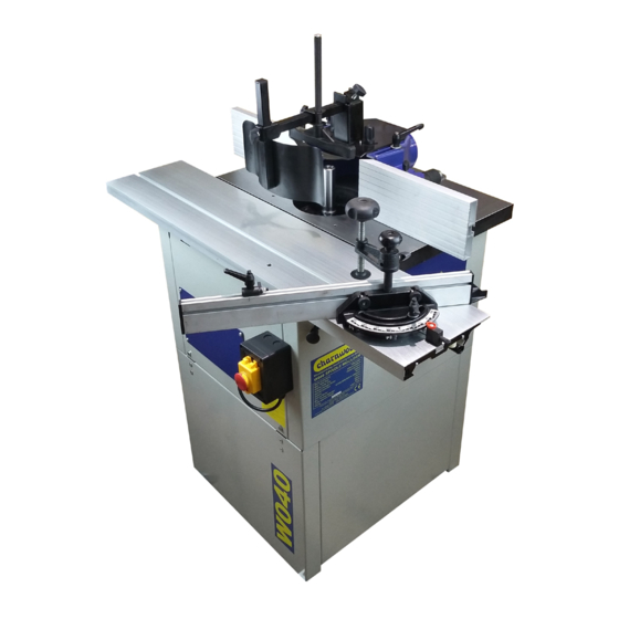
- Page 1 SPINDLE MOULDER OPERATING INSTRUCTIONS MODEL: W040 Charnwood, Cedar Court, Walker Road, Hilltop Industrial Estate, Bardon Hill, Leicestershire, LE67 1TU Tel. 01530 516 926 Fax. 01530 516 929 email: sales@charnwood.net website: www.charnwood.net...
-
Page 2: Use Of The Machine
Forward These instructions are important, the information contained herein is essential for the correct build and operation of the machine and the safety of its operator. The machine is equipped with various safety devices to protect itself and the operator. However, these devices cannot cover all eventualities and a thorough understanding of spindle moulding techniques, good workshop practice plus the controls and operation of this machine are essential for your safety. - Page 3 5. Keep your work area clean. Cluttered areas and workbenches increase the chance of an accident.' 6. Do not use in dangerous environments. Do not use power tools in damp or wet locations, or expose them to rain. Keep work areas well illuminated. 7.
-
Page 4: Specification
3. Guards should be of such a design and fitted in such a way that they keep fingers out of an area of 50 mm (2 inches) beyond the sweep of any cutter that might be used. 4. Always ensure that you use safe working procedures and that you understand what you are doing. - Page 5 Unpacking This product is shipped in 4 Pieces: 1 wooden crate and 3 cartons. To open the wooden crate cut the strapping and lift the lid of the crate from the base. Remove the loose items which are packed in the table recess. Open the hinged blue door situated on the side of the machine.
- Page 6 The machine is fixed to the pallet with two brackets. Use a pair of 13mm spanners to undo the securing bolts and remove the brackets. Close and secure the blue door. Please Note: This part of the assembly requires 2 people. Clear a floor area and invert the body of the machine, so it sits upside down on the cast iron table.
- Page 7 Assembly To assemble the base. Locate: 4 x Panel 4 x Feet 8 x M6 Bolt, Washer and nut 4 x Joining Bracket Screw the 4 feet into the threaded holes in the 2 side panels of the base. Use a 17mm spanner to tighten them.
- Page 8 Turn the cabinet base the correct way up. Remove all of the bolts from the 4 joining brackets. Use 2 bolts to attach each joining bracket to the assembled base. Fit the base to the cabinet. The projecting part of each joining bracket aligns with a hole in the main cabinet.
- Page 9 Slot (See below) Remove one of the nylon stops from the underside of the sliding beam, using a no.3 Philips head screwdriver. Lower the retractable sliding beam lock, by moving the lever down and to the left, slide the beam onto the guide rollers.
- Page 10 Locate the spindle lock bar on the right hand side of the machine. Rotate the tapered spindle slowly whilst pressing the locking bar inwards. When the lock engages the bar will slide in around 10mm and the spindle will be locked. Pull the bar out to unlock the spindle.
- Page 11 The router collet is mounted in the same way. When changing the router cutter, take the precaution of checking the centre retaining screw is tight Assemble the fence; Fence depth locking screw Fence depth Adjusting screw. Fence fixing plate. Fence width lock. On top of the hood, you will find four screws.
- Page 12 Fit the 2 long bolts through the slots in the hood and then screw them into a pair of holes in the table. The hood can be fixed in different positions depending on the size of the work piece. The cover is hinged to provide quick access to the spindle to change the tooling.
- Page 13 Assemble the front guard and clamp. Fit the square bar into the hood cover and lock it with the thumbscrew. Slide the vertical hold down onto the square bar and lock it with the thumb screw. Fit the front spring guard into the end of the square bar and lock it with the thumb screw.
- Page 14 The long fence can be adjusted left and right to suit the diameter of tooling to be used. The work clamp can be used to clamp a work piece. Screw the thread down to engage the clamp. The flip over length stop can be raised or lowered as shown.
-
Page 15: Changing Speed
Before fitting the cutter block onto the spindle, engage the spindle lock. Now fit, (in reverse order): The locking bolt The top cap the spacer with the roll pin some spacers the cutter block some more spacers The locking bolt must be firmly tightened. - Page 16 Slacken off the locking lever Reduce the tension on the drive belt by moving this lever. Move the drive belt to the pair of pulleys which give the required speed, re-tension the belt and then tighten the locking lever. Operating the Spindle Moulder It is assumed that anyone purchasing a spindle moulder has been trained to operate this type of machine competently.
-
Page 17: Declaration Of Conformity
Declaration of Conformity Charnwood Declare that Woodworking Spindle Moulder, Model W040 Conforms with the following EU Directives: Machinery Directive 2006/42/EC Low Voltage Directive 2006/95/EC Conforms with the following UK Regulations: Supply of Machinery (Safety) Regulations 2008 Electrical Equipment (Safety) Regulations 2016 And further conforms to the machinery example for which the EC type examination Certificate No., have... - Page 18 Main Assembly – Diagram A...
- Page 19 Description Description Foot M8 x 25mm setscrew Front panel Washer L.H. panel Motor M4 x 10 mm setscrew M8 Nut Washer Spring washer M4 nut Washer M6 nut M8 x 25 mm setscrew Washer Washer M6 x 16 bolt Housing Access cover M8 x 12 mm setscrew Knob...
- Page 20 Motor and spindle assembly – Diagram B...
- Page 21 Description Description B01 Setscrew M6 x 16 mm B33 Motor mount B02 Washer B34 Bearing B03 Stepped pulley (driven) B35 M6 x 60 mm setscrew B04 Circlip B36 Handle B05 Bearing B37 Washer B06 M5 x 12 mm bolt B38 M6 nut B07 Washer B39 Hand wheel B08 Bush...
- Page 22 Fence / Hood Assembly – Diagram C Description Description C01 Fence fore & aft adjuster C19 n/a C02 Cutter hood C20 n/a C03 Fence backing plate C21 n/a C04 Flange headed bolt C22 n/a C05 Setscrew C23 Hold down column C06 Semicircular locking plate 2 C24 Plastic cap C07 M4 x 12 mm bolt...
- Page 23 Sliding Beam Assembly – Diagram D...
- Page 24 D62 Knob D31 Bolt D63 Knob D32 Flip-over end stop D64 Roll pin Updated May 2021 Charnwood, Cedar Court, Walker Road, Hilltop Industrial Estate, Bardon Hill, Leicestershire, LE67 1TU Tel. 01530 516 926 Fax. 01530 516 929 email: sales@charnwood.net website: www.charnwood.net...
Need help?
Do you have a question about the W040 and is the answer not in the manual?
Questions and answers