Table of Contents
Advertisement
Advertisement
Table of Contents

Related Manuals for XICOY X45

Summary of Contents for XICOY X45
- Page 1 icoy 45/90/120 TurboJet Engines User Manual Version 1.2/2021 Page 1...
- Page 2 Congratulations on your purchase of a new generation Xicoy “X” Series gas turbine engine. We are confident you will be pleased with your purchase and your new engine will give you excellent ser- vice and maximum enjoyment to your hobby.
-
Page 3: Table Of Contents
User’s Manual or its link, so they can enjoy a safe and fulfilling ownership too. The Xicoy Electronica SL responsibility is limited exclusively to the repair of the engine and acces- sories which are outlined in the conditions of warranty. - Page 4 Auto Power-Off..........................18 Hub installed ambient sensors ....................18 Fuel Pump ............................19 Construction..........................19 Pre-setting............................. 20 ECU Display ............................21 ECU data record / playback ....................... 21 Plug-in backlit display........................22 Navigating Menu Screens ....................... 23 Engine Installation: Electrical connections .................. 28 Shared ECU battery ........................
-
Page 5: Legal And Disclaimer
The engine design and contents of this User Manual are copyright Xicoy Electronica SL, Canet de Mar, Barcelona, Spain. All rights are reserved. This User manual, pictures and data are the property of Xicoy Electronica SL and cannot be used or reproduced in any way with written permission from Xicoy Electronica SL. - Page 6 This warranty is voided if any one or more of the following conditions applies. In such a case Xicoy Electronica SL will accept no responsibility for any damage or other consequence caused by engine operation.
-
Page 7: Safety Notes
Safety Notes Please remember that though this engine is small it is most definitely NOT a toy and has the po- tential to hurt you or others around you if misused. The engine is a very high performance ma- chine in miniature and must always be treated with a high level of care and safety when in your operation. -
Page 8: General Notes
General Notes This engine is a real gas turbine machine with very high rotational speeds and high temperature fast moving exhaust. Despite the small intake the engine is able to swallow a huge amount of air and anything else that air can carry with it. So before running please carefully check the area sur- rounding the front and back end of the engine for any loose materials like rags, sawdust, sand or grit, modelling materials, liquids, or anything else that can be picked up by the airstream and sucked into the engine, or blown out at speed by the exhaust. - Page 9 (usually orange or white) is a digital signal line so DC power should not be applied to this line or attempts made to read the voltage on this line for fault-finding purposes. Please refer to the Xicoy office for guidance in the first instance in event of any issue. Page 9...
-
Page 10: Engine Specifications
Engine Specifications X120 Engine diameter 60mm / 2.35” 76mm / 3” 90mm / 3-1/2” Length 160mm / 6.3” 183mm / 7.2” 198mm / 7.8” Engine weight 398g / 14oz 706g / 1.6Lb 940g / 2.1Lb Total installed weight 470g / 16.5oz 888g / 1.8Lb 1140g / 2.5Lb Nominal thrust at sea... -
Page 11: Battery Consumption
Use at least 25C batteries, there is no upper limit. Do not use other battery types like LiIon, these batteries cannot deliver the peak amperage (20-30A) necessary for starting. Battery consumption As example in mAh battery use, on average the X45 engine uses: Start-up: 100mAh for X45 About 20mAh -30mAh for each minute running (depends on throttle position). - Page 12 Do not use 2 stroke oil alone (4%). This will gum the bearings causing difficult or impossi- ble start-up when engine is cold. Please refer to the Xicoy Office for guidance in the first instance in event of any issue or concern. Page 12...
-
Page 13: Engine Description
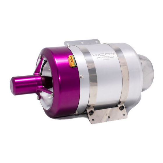
Engine Description The X series engines are miniature turbojets designed and produced specifically to produce thrust to power small model aircraft. Each has a single stage billet machined centrifugal compressor and single stage cast Inconel axial flow turbine mounted on a single shaft. The engine is fitted with a long life replaceable ceramic glowplug which enables the engine to initiate combustion directly on liquid fuel after which further fuel is gradually introduced into the main part of the combustion chamber to provide combustion heat to operate the engine. - Page 14 This is also the location to connect the ECU battery. If battery is sited at some distance perhaps in the nose of the aircraft, please contact Xicoy and ask for a longer cable in one piece. Please don´t cut it and splice in a couple of old bits of wire to make it longer. A heavy duty exten- sion can be used but check polarity before plugging in.
- Page 15 If an extended exhaust duct (internal tailpipe) for internal installation is required, it should be diameter as shown in the Specifications, and stiff enough to resist flattening in the airflow. Leave a gap of 25mm (1”) from tip of the exhaust to the end of the duct (excluding bell mouth length).
-
Page 16: Component Description
The ECU and indeed the whole system used on these engines are totally new and unlike any pre- vious version of Xicoy ECU. It is a new controller developed specifically for this application by Xicoy Electronica which is in the form of a small C-shaped pcb fitted under the front cover of the engine. -
Page 17: Kero/Diesel Selector
Kero/Diesel Selector The kero/diesel option which switches between preset routines for each fuel. This saves you the ordeal of having to make many adjustments to fine tune the starting every time you switch fuels, now you just press a button to click your fuel, and go. Diesel being heavier and higher flashpoint fuel than kerosene requires a different start technique to enable it to start quickly and cleanly. -
Page 18: Auto Power-Off
Bluetooth connectivity possible using dedicated module.The Xicoy website, www.xicoyturbines.com will show what is available for the “X” Series engines at any time, new Page 18... -
Page 19: Fuel Pump
Hubs have a printed panel showing where each cable goes and the orientation of each plug. For all cables, if you need a longer or shorter version than supplied, please contact Xicoy. Do not cut or splice in extra wire. -
Page 20: Pre-Setting
Use the piping supplied. The ring on the metal filter denotes the outlet to go to the pump. Do not run the engine without a filter. The X45 and X90 use 4mm inlet and outlet, the X120 has a 6mm inlet and 4mm outlet. -
Page 21: Ecu Display
Priming It is strongly recommended that after a new installation or modification to the fuel system that the system be primed to clear any debris collected in the fuel line before connecting to the engine: engine does not (Note the itself require any priming) To prime the fuel system, disconnect the fuel pipe at the engine and route it into a suitable con-... -
Page 22: Plug-In Backlit Display
All the data, including all engine parameters, can also be saved later to a memory card, where it can be read using a text editor, or our viewer software. Also this data can be sent to Xicoy to be studied. -
Page 23: Navigating Menu Screens
Navigating Menu Screens The screen display is straight forward to navigate once you get the hang of it. We use the backlit display but the Compact Hub display is very similar, just follow the buttons. Start by plugging in the display to see the open screen. Note there are four buttons underneath the dials, <... - Page 24 Next is the setting for minimum pump speed during the start. Only adjust this if the combustion is slow to get going. 100 is the usual default and it increments at 25 a time with + and – buttons. Too high a setting will make flames at the starting. Leave it as factory set.
- Page 25 Total time counter. This screen shows the total runtime in hours of the engine since new. It also shows engine serial number and software version. Test starter screen. This screen is used to test the action of the starter by pressing the button under the “On”.
- Page 26 Test Fuel Valve. This test refers to the valve supplying the main fuel supply to the combustion chamber of the engine. The only test you can do is press the button beneath the “On” and you hear a click from the front of the engine, to signal all is ok. Is a rarely used function.
- Page 27 This is pre-set at Auto, the actual speed dependent on the engine, which allows the ECU to modify the setting in response to atmospher- ic conditions. (X45 shown) In hot or conditions of high altitude or low air pressure the ECU will raise this value.
-
Page 28: Engine Installation: Electrical Connections
Engine Installation: Electrical connections The “X” Series engines are very simple to install but main thing to be very careful of is any cable or battery connector which is not standard or has been modified in some way, as this can risk re- verse connection of power supply which will easily destroy ECU and other components, so please be extra vigilant before using junkbox cables and/or adapters. -
Page 29: Radio Setup
ECU setup The ECU is contained on the engine. All the operating parameters relating to the starting and run- ning of the engine are contained in its memory. All communications with the outside world occurs through the cable connected to the external Hub unit. The signal from the user’s radio receiver throttle channel is used to initiate and control all functions relating to engine operation. -
Page 30: Aligning Transmitter With Ecu
ducing the “trim-down” function. Using a digital trim cause unstable idle, and delay in shutting off the engine in emergency. Check your radio manual for this before you start. Avoid using the digital trim if at all possible. Do not to use a spring loaded “Throttle Cut” switch as it will prevent the engine carrying out the cooldown function. -
Page 31: Failsafe
Use at least 20mm/3/4” long for the X45 and 25mm/1” for X90 and X120, to be sure the engine is properly secure. A platform/table/workbench is required to clamp or fix the test stand onto. Make sure this can be easily transported outside and weight enough to ensure it cannot be blown over by the thrust of the engine. -
Page 32: During Start-Up - General
cient, then it will be ignited in the exhaust, causing a hot start (in extreme cases a big fireball) that surely will not hurt the engine, but can destroy the model. So: During start-up - general During the start-up listen to the engine sound to check for positive sound of ignition, check looking from the exhaust that the kero is burning, or check for an increase in exhaust temperature in the display. -
Page 33: Starting The Engine
repeating. Pushing fuel directly into the engine will cause an uncontrolled fire at next startup. Starting the engine Set the throttle stick down and the trim up (“Idle”). Confirm that the screen shows "Ready" i.e. Ready to start! In the case that the exhaust temperature is over 100º, the ECU will power the starter to cool down the engine. -
Page 34: Adjusting The Engine Maximum Power
Adjusting the engine maximum power. The engine comes from factory adjusted for its maximum thrust. But it is possible to reduce the maximum power if necessary. To do so, go to RUN menu and scroll the menus up to “Max RPM”. Using the + and –... - Page 35 Manual restart: User can normally shutdown the ECU through the transmitter (by lower- ing the stick and trim). The ECU will execute the normal shutdown and post run cooling cycle. Once the cooling is finished (temperature below 100ºC), the ECU will return to power-up state allowing the engine to be restarted through the normal procedure (Trim-up, cycle stick).
- Page 36 sustaining enough flight for the re-start to be completed. Some aircraft examples include: lightly loaded planes, gliders, or multi engine planes. It is highly advised that a shutdown simulation be done before selecting Auto-restart option in the ECU RADIO menu. Do it during a normal flight at a high altitude, then throttle down to idle then begin a 10sec count down.
-
Page 37: Restart Disclaimer
Restart Disclaimer There are no circumstances Xicoy Electronica SL or any of its Service Agents and employees will accept or be held responsible for any losses or damages the Auto Restart feature causes should the owner operator choose to enable this function. - Page 38 normal use. However the user can modify these default settings to allow the engine to run opti- mally in different conditions. The usual acceleration setting are set to AUTO which gives the engine a good response but tries to minimise the risk of over-fuelling in a sudden acceleration. In AUTO mode, the ECU adjusts itself for optimum running at the current ambient conditions reported by the sensors built into the Hub, and in extreme cases it also raises the idle speed accordingly.
-
Page 39: Diagnoses
Ready: Indicates that the engine is ready for starting, and that the transmitter signal cor- responds to IDLE, (LED lit twice) StickLo!: This indicates that the throttle stick is in a position above IDLE, the engine will not start with the stick in this position. Glow Test: Verification of glow plug StartOn: Test of the starter and rpm sensor Ignition: Ignition phase. -
Page 40: Diagnosis Messages
RCPwFail: Lack of power from the radio receiver. Telemetry: Xicoy Electronica offers several additional modules that allow transmitting the engine data in real time to an external receiver. Using the Blue1 module is possible to connect to Android and Apple smartphones.
Need help?
Do you have a question about the X45 and is the answer not in the manual?
Questions and answers