
Related Manuals for Emerson PACSystems RSTi-EP EPSCPE100


Summary of Contents for Emerson PACSystems RSTi-EP EPSCPE100
- Page 1 QUICK START GUIDE GFK-3012E Feb 2020 PACSystems RSTi-EP STANDALONE 1GHz PROGRAMMABLE CONTROLLER (EPSCPE100)
-
Page 2: Table Of Contents
Contents User Features ....................2 Membrane Run/Stop Pushbutton ..................4 LED Indicators (LEDs) ......................4 Ethernet Status Indicators..................4 Module Status Indicators ..................4 Ethernet Ports ........................6 Typical Network Application ..................7 Multi-Tier Networks ....................8 USB Port ..........................9 Serial Ports ......................... - Page 3 Modbus RTU Configuration ..................19 Serial I/O Configuration ..................19 Performance with Typical Configuration ................. 20 Product Limitations ..................21 Replacement of Internal Supercapacitor............22 Troubleshooting .................... 25 Additional Information .................. 29 PACSystems™ RSTi-EP EPSCPE100 Standalone CPU Quick Start Guide GFK-3012E...
- Page 4 These instructions do not purport to cover all details or variations in equipment, nor to provide for every possible contingency to be met during installation, operation, and maintenance. The information is supplied for informational purposes only, and Emerson makes no warranty as to the accuracy of the information included herein. Changes, modifications, and/or improvements to equipment and specifications are made periodically and these changes may or may not be reflected herein.
-
Page 5: User Features
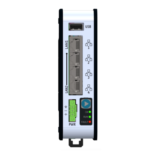
User Features The PACSystems™ RSTi-EP EPSCPE100 (or CPE100), is an enhanced performance standalone 1GHz programmable controller equipped with 1 MB of user memory and four Ethernet ports. It is designed to run real-time, deterministic control applications and supports distributed I/O. LAN 1 is a dedicated high-speed Ethernet port. - Page 6 8 Clients total are permitted and may be a combination of SRTP or Modbus/TCP. Up to 8 simultaneous Class 1 Ethernet Global Data (EGD) exchanges. When used in combination for optimal performance, use must not exceed 4 Channels for Server (Modbus/SRTP) and 4 Channels for client (Modbus/SRTP), 8 PROFINET nodes and 8 EGD data exchanges.
-
Page 7: Membrane Run/Stop Pushbutton
Membrane Run/Stop Pushbutton Figure 1: Start/Stop Pushbutton The Membrane Run/Stop push button is located at the bottom right of the front panel (see Figure 1). Pressing it briefly, will change the state of CPU from the state it is in to the next state. It acts as a toggle switch, as shown in the following state diagram: The Run/Stop switch is enabled by default;... - Page 8 LED LED State Operating State (at Power-Up) Blinking; All This LED indicates the status of PLC during powering other LEDs off up. It starts blinking 6 seconds after applying power to the PLC and remains in this state for up to 15 seconds. After this all LEDs turn off and will remain in this state until PLC is ready.
-
Page 9: Ethernet Ports
Ethernet Ports CPE100 provides two independent Fast Ethernet LANs. LAN1 has only one port and is dedicated to the embedded Ethernet controller. LAN2 is comprised of 3 switched ports, each configurable either as a second embedded Ethernet controller or as an embedded PROFINET controller. -
Page 10: Typical Network Application
Typical Network Application A typical application will take advantage of the two independent LANs. The dedicated LAN1 port will be used for communications with plant-level or supervisory layers. The switched LAN 2 will be used to communicate with devices over PROFINET within the manufacturing cell or process. -
Page 11: Multi-Tier Networks
Multi-Tier Networks Whenever CPE100 is configured for MRP only, Ethernet Port2 & Port3 of LAN2 may be used to form a ring. Ethernet Port4 of LAN2 may still be used either to connect to the programmer, to a simplex PROFINET device or to any other supported Ethernet protocols. -
Page 12: Usb Port
USB Port CPE100 has one USB Port located on top of the front panel, but currently it is disabled for security reasons. Serial Ports CPE100 supports both the RS-232 and RS-485 ports. RS-485 port supports only two modes of operations 2-Wire and 4-Wire. These ports are located on the underside of the controller (Figure 5). - Page 13 RS-232 RS-485 Signals Signals Pins The Serial Port Setup COMMREQ function can be used to activate a Modbus RTU protocol over a serial port. To configure the Serial Port COMMREQ Data Block on CPE100, refer to section 6.1.6 of the document PACSystems RX3i and RSTi-EP CPU Reference Manual, GFK-2222.
-
Page 14: Hardware Installation
As the consignee, it is your responsibility to register a claim with the carrier for damage incurred during shipment. Emerson will fully cooperate with you, however, should such action be necessary. -
Page 15: Instructions For Mounting The Cpe100 On A Din Rail
Instructions for Mounting the CPE100 on a DIN Rail The CPE100 snaps easily onto the DIN rail, as shown in Figure 3. No additional tools are required. Incline the unit so that the upper hooks of the DIN rail adaptor engage with the upper edge of the DIN rail. -
Page 16: Instructions For Mounting The Cpe100 On A Panel
Instructions for Mounting the CPE100 on a Panel Attach the panel mount plate to the rear side of CPE100 using the four M3 screws supplied with the adapter. Fasten the tabs of panel mount adapter in the appropriate location of panel with the four screws. -
Page 17: Grounding
Grounding Proper grounding of the CPE100 is essential. Use the ground terminal located on the underside, as shown in Figure 8. Use a 16-22 AWG braided wire with lugs to connect the ground terminal of the CPE100 to a suitable ground stud in the enclosure panel, or to the DIN Rail. -
Page 18: Module Start-Up
Module Start-up Power-Up Time The CPE100 requires at a minimum 35 to 40 seconds to complete power-up. When power is applied, all the Ethernet Port LEDs blink once. When power up is complete, the OK LED turns on and remains steady whereas the RUN LED indicates the current run mode. -
Page 19: Basic Installation Steps
• Ethernet cable for connecting the PME programmer computer to the CPE100. • Very small slotted screwdriver (2 mm jeweler’s size) for securing wires to the connector shown in Figure 10. Basic Installation Steps: For start-up and configuration of the CPE100, complete the following steps: Be sure to disconnect the power to CPE100. -
Page 20: Programming The Cpe100
Programming the CPE100 To configure the CPE100, connect the computer running the PME programming software to an Ethernet port of LAN1 using the default IP address 192.168.0.100. PME 9.5 SIM 1 or later is required. Configuration will either start out using the RSTi-EP CPE100 template when creating a new project or will convert an existing project to the CPE100 using the Family Conversion feature in PME. -
Page 21: Opc Ua Server Configuration
Figure 11: Configuring as an Embedded PROFINET Controller OPC UA Server Configuration To configure CPE100 as OPC UA server, refer to chapter 10 of the document PAC Systems RX3i and RSTi-EP TCP/IP Ethernet Communications User Manual, GFK-2224. Serial Port Configuration CPE100 provides two serial ports - COM1(RS-232) and COM2(RS-485). -
Page 22: Modbus Rtu Configuration
Modbus RTU Configuration The CPE100 can be configured as a Modbus RTU Slave device using either or both the serial ports (RS-232 and RS-485) located on the underside of the controller. The Serial Port Setup COMMREQ function can be used to activate a Modbus RTU protocol over a serial port. -
Page 23: Performance With Typical Configuration
Performance with Typical Configuration The below diagram shows the system configuration with four CPE100 connected to one PROFINET I/O node each and interfaced to one RX3i CPE400 with four EGD exchanges each. Out of 4 CPE100 units two of them are connected to Modbus RTU Master having RS-232 and RS-485 Serial connections. -
Page 24: Product Limitations
For more details on the configuration of the above set-up and the typical loopback time across all the PROFINET nodes, please refer to GFK-3086. It also documents other examples of system configurations and the performance limitations of this product. Product Limitations Timed interrupt blocks are not supported. -
Page 25: Replacement Of Internal Supercapacitor
Replacement of Internal Supercapacitor The supercapacitor board associated with the CPE100 is EPSACC001. Use this part number when ordering replacements. Do not attempt to use any other replacement part for this procedure. WARNING • Perform all electrical replacements in a suitably clean and dry environment. Clean away all surface contaminants before opening the electrical circuit enclosure. - Page 26 Detach the side panel cover (Figure 13) by removing the (M3) screws with a Phillip’s head screwdriver. Figure 13: Controller Side Panel Figure 14: Supercapacitor Board Location Using a screwdriver, remove the two M2.5 screws and detach the supercapacitor card from the carrier board (Figure 15). Disconnect the mating connectors.
- Page 27 Using the reverse procedure, install the new supercapacitor card onto its carrier board. Check that the mounting holes are aligned properly before tightening both the M2.5 screws. Recommended torque is= 3 in-lb (0.3 Nm). Reconnect the mating connectors. Verify the assembly has been restored as shown in Figure 14. 10.
-
Page 28: Troubleshooting
Troubleshooting Why does my controller not power on after I apply power? (None of the front panel LEDs are illuminated.) The incorrect power supply may be used. Verify that the correct power supply is connected, and that the Figure 17: CPE power connector is fully seated. - Page 29 How can I restore the default IP address or perform a Figure 18: Run/Stop factory reset on my controller? Pushbutton To reset the IP Address to its default (192.168.0.100) or to perform a factory reset, complete the following: User needs to power down the controller. Press and hold the membrane Run/Stop pushbutton (Figure 18) during power up.
- Page 30 How can I recover the controller from the Stop/Faulted state? A Stop/Faulted state cannot persist through a power cycle. To recover the controller, there are two methods: Power cycle the controller Perform a CLEAR operation from the PME software. When should I replace the internal supercapacitor? Whenever a “Failed Battery Signal”...
- Page 31 How to reset the firmware update password? Use programming software or the controller’s RUN/STOP pushbutton (if enabled in the hardware configuration) to place the RSTi-EP Controller module in Stop Disabled mode Open a browser window and go to the PACSystems RSTi-EP Controller’s homepage using the IP address assigned to the controller’s embedded LAN 1 or LAN 2 Ethernet ports.
-
Page 32: Additional Information
Additional Information PAC Logic Developer-PLC Getting Started Guide GFK-1918 PACSystems RX3i and RSTi-EP CPU Reference Manual GFK-2222 PACSystems RX3i and RSTi-EP TCP/IP Ethernet Communications User’s Manual GFK-2224 PACSystems RX3i System Manual GFK-2314 PACSystems RXi, RX3i, and RSTi-EP Controller Secure Deployment Guide GFK-2830 PACSystems RX3i &... - Page 33 Emerson product remains solely with the purchaser. © 2020 Emerson. All rights reserved. Emerson Terms and Conditions of Sale are available upon request. The Emerson logo is a trademark and service mark of Emerson Electric Co. All other marks are the property of their respective owners.
Need help?
Do you have a question about the PACSystems RSTi-EP EPSCPE100 and is the answer not in the manual?
Questions and answers