
Related Manuals for Panasonic PAN1326C


Summary of Contents for Panasonic PAN1326C
- Page 1 PAN1326C Bluetooth Basic Data Rate and Low Energy Module Product Specification Rev. 1.0 Wireless Modules...
- Page 2 PAN1326C Bluetooth Module Overview Features • Panasonic’s new PAN1326C is a Host Controlled Bluetooth-4.2-compliant up to the HCI layer • Interface (HCI) Bluetooth RF module that brings Best-in-class Bluetooth RF performance (Tx, Rx Texas Instrument’s seventh generation Bluetooth sensitivity, blocking) •...
- Page 3 By purchase of any of the products described in this document the customer accepts the document's validity and declares their agreement and understanding of its contents and recommendations. Panasonic reserves the right to make changes as required at any time without notification. Please consult the most recently issued Product Specification before initiating or completing a design.
-
Page 4: Table Of Contents
PAN1326C Bluetooth Module Table of Contents About This Document ......................... 5 Purpose and Audience ......................5 Revision History ......................... 5 Use of Symbols ......................... 5 Related Documents ........................5 Overview .............................. 6 Block Diagram ........................... 7 Pin Configuration ........................8 Device Power Supply....................... -
Page 5: About This Document
1.1 Purpose and Audience This Product Specification provides details on the functional, operational, and electrical characteristics of the Panasonic PAN1326C module. It is intended for hardware design, application, and Original Equipment Manufacturer (OEM) engineers. The product is referred to as “the PAN1326C” or “the module” within this document. -
Page 6: Overview
RF performance with about twice the range of other Bluetooth Low Energy solutions. Panasonic’s tiny footprint technology has produced a module of only 85.5 mm². The module is designed to accommodate PCBs pad pitch of 1.3 mm and as few as two layers for easy implementation and manufacturing. -
Page 7: Block Diagram
PAN1326C Bluetooth Module 2 Overview 2.1 Block Diagram PAN131x Vcc 3.3 V Bluetooth 4.2 Module UART Crystal GPIOs 26 MHz Texas Instruments CC256x Audio PCM/I2C BT-HCI Chip Reset 32 kHz input RF-Pad PAN132x Vcc 3.3 V Bluetooth 4.2 Module... -
Page 8: Pin Configuration
PAN1326C Bluetooth Module 2 Overview 2.2 Pin Configuration Pin Assignment PAN1316C Top View 9,00 mm Pad = 24 x 0.60mm x 0.60mm Module Height 1.8 mm Top View PIN Assignment PAN1326C 0,55 9.00 Pad = 28 x 0.60mm x 0.60mm Top View Product Specification Rev. - Page 9 PAN1326C Bluetooth Module 2 Overview Pin Functions Pin Name Pull at Def. I/O Type Description Reset Dir. Connect to Ground TX_DBG 2 mA Logger output HCI_CTS 8 mA HCI UART clear-to-send. HCI_RTS 8 mA HCI UART request-to-send. HCI_RX 8 mA...
- Page 10 PAN1326C Bluetooth Module 2 Overview For RF conducted measurements either use the PAN1323ETU or de-solder the antenna and solder an antenna connector to the hot pin. Pin Description Pull at Def. Pin Name I/O Type Description of Options Reset Dir.
-
Page 11: Device Power Supply
PAN1326C Bluetooth Module 2 Overview 2.3 Device Power Supply The PAN13x6C Bluetooth radio solution is intended to work in devices with a limited power budget such as cellular phones, headsets, hand-held PC’s and other battery-operated devices. One of the main differentiators of the PAN13x6C is its power management – its ability to draw as little current as possible. - Page 12 PAN1326C Bluetooth Module 2 Overview There are three ways to supply power: 1. Full-V system (Maximum RF output power, but not optimum system power): 2. Full-DC2DC system (Lower RF output power, but optimum system power): 3. Mixed DC2DC-V system (Maximum RF output power and optimum system power, but...
-
Page 13: Clock Inputs
PAN1326C Bluetooth Module 2 Overview 2.4 Clock Inputs The slow clock is always supplied from an external source. It is connected to the SLOW_CLK_IN pin number 8 and can be a digital signal with peak to peak of 0-1.8 V. -
Page 14: Interfaces
PAN1326C Bluetooth Module 2 Overview 2.6 Interfaces 2.6.1 Host Controller Interface (HCI) The CC2564C incorporates one UART module dedicated to the host controller interface (HCI) transport layer. The HCI interface transports commands, events, ACL, and synchronous data between the Bluetooth device and its host using HCI data packets. - Page 15 MHz, the maximum data burst size is 32 bits. For master mode, the CC2564C can generate any clock frequency between 64 kHz and 6 MHz. When the I2S bus is used in an application, Panasonic recommends adding a low pass filter (series resistor and capacitor to GND) to the bus for better noise suppression. Connecting the host μController/DSP directly with the module’s I2S interface is not recommended.
- Page 16 PAN1326C Bluetooth Module 2 Overview • The data position within a frame is also configurable in with 1 clock (bit) resolution and can be set independently (relative to the edge of the Frame Sync signal) for each channel. •...
- Page 17 PAN1326C Bluetooth Module 2 Overview 2.6.2.4 Clock-Edge Operation The codec interface of the CC2564C can work on the rising or the falling edge of the clock. It also has the ability to sample the frame sync and the data at inversed polarity.
- Page 18 PAN1326C Bluetooth Module 2 Overview 2.6.2.7 Improved Algorithm For Lost Packets The CC2564C features an improved algorithm for improving voice quality when received voice data packets are lost. There are two options: • Repeat the last sample – possible only for sample sizes up to 24 bits. For sample sizes >24 bits, the last byte is repeated.
-
Page 19: Detailed Description
PAN1326C Bluetooth Module 3 Detailed Description 3 Detailed Description 3.1 Dimensions All dimensions are in millimeters. 3.1.1 PAN1316C Module Drawing Item Dimension Tolerance Remark 0.30 1 Width 6.50 0.30 2 Length 9.00 0.20 3 Height 1.80 With case Product Specification Rev. - Page 20 PAN1326C Bluetooth Module 3 Detailed Description 3.1.2 PAN1326C Module Drawing Item Dimension Tolerance Remark 0.30 1 Width 9.50 0.30 2 Length 9.00 0.20 3 Height 1.80 With case Product Specification Rev. 1.0 Page 20...
-
Page 21: Footprint
PAN1326C Bluetooth Module 3 Detailed Description 3.2 Footprint • The outer dimensions have a tolerance of 0.2 mm. • The layout is symmetric to center. • The inner pins (2, 4, 6, 9, 11, 14, 16, 18, 21, and 23) are shifted to the center by 1 mm. - Page 22 PAN1326C Bluetooth Module 3 Detailed Description 3.2.2 Footprint - PAN1326C With Antenna Product Specification Rev. 1.0 Page 22...
-
Page 23: Packaging
PAN1326C Bluetooth Module 3 Detailed Description 3.3 Packaging The product is a mass production status product and will be delivered in the package described below. 3.3.1 Tape Dimensions 3.3.1.1 PAN1316C Without Antenna SECTION SCALE 3.5 SECTION SCALE 3.5 6.90 +/- 0.10... - Page 24 PAN1326C Bluetooth Module 3 Detailed Description 3.3.2 Packing in Tape 3.3.2.1 PAN1316C without antenna Direction of unreeling (for customer) Top cover tape more component trailer (empty) leader (empty) than 1 x packed area 1 x circumference / minimum 10 pitch...
- Page 25 PAN1326C Bluetooth Module 3 Detailed Description 3.3.3 Component Direction Pin 1 Marking (Top Side) Direction of unreeling Pin 1 Marking (for customer) (Bottom Side) Circle r = 0.5 mm on solder resist near Pin 1 3.3.4 Reel Dimension Product Specification Rev. 1.0...
- Page 26 PAN1326C Bluetooth Module 3 Detailed Description 3.3.5 Package Label Example (1T) Lot code (1P) Customer order number, if applicable (2P) Order number (9D) Date code Quantity (HW/SW) Hardware/software version 3.3.6 Total Package Product Specification Rev. 1.0 Page 26...
-
Page 27: Case Marking
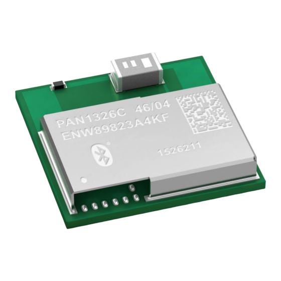
PAN1326C Bluetooth Module 3 Detailed Description 3.4 Case Marking Example Brand name Hardware/software version Order number 2D Data Matrix Code Lot code Marking for Pin 1 Product Specification Rev. 1.0 Page 27... -
Page 28: Specification
PAN1326C Bluetooth Module 4 Specification 4 Specification All specifications are over temperature and process, unless indicated otherwise. 4.1 Default Test Conditions Temperature: 25 ± 10 °C Humidity: 40 to 85 % RH Supply Voltage: 3.3 V 4.2 Absolute Maximum Ratings The maximum ratings may not be exceeded under any circumstances, not even momentarily or individually, as permanent damage to the module may result. -
Page 29: Recommended Operating Conditions
PAN1326C Bluetooth Module 4 Specification 4.3 Recommended Operating Conditions The maximum ratings may not be exceeded under any circumstances, not even momentarily or individually, as permanent damage to the module may result. Rating Condition Symbol Unit Power supply voltage... -
Page 30: Nshutd Requirements
PAN1326C Bluetooth Module 4 Specification 4.5 nSHUTD Requirements Parameter Symbol Unit Operation mode level 1.42 1.98 Shutdown mode level Minimum time for nSHUT_DOWN low to reset the device Rise/fall times Tr/Tf µs 4.6 External Digital Slow Clock Requirements Characteristics... - Page 31 PAN1326C Bluetooth Module 4 Specification BT Spec BT Spec Characteristics Class1 Class1 Average Power Hopping DH5 [dBm] 11,3 Average Power: Ch0 [dBm] 11,4 Peak Power: Ch0 [dBm] 11,6 Average Power: Ch39 [dBm] 11,3 Peak Power: Ch39 [dBm] 11,6 Average Power: Ch78 [dBm]...
- Page 32 PAN1326C Bluetooth Module 4 Specification BT Spec BT Spec Characteristics Class1 Class1 ACPower +2: Ch3 [dBm] -50.7 ACPower +3: Ch3 [dBm] -53.3 ACPower -3: Ch39 [dBm] -51.6 ACPower -2: Ch39 [dBm] -50.7 ACPower -1: Ch39 [dBm] -19.0 ACPower Center: Ch39 [dBm] ACPower +1: Ch39 [dBm] -19.7...
-
Page 33: Reliability Tests
PAN1326C Bluetooth Module 4 Specification BT Spec BT Spec Characteristics Class1 Class1 omega i 3-DH5: Ch78 [kHz] -3.8 omega o + omega i 3-DH5: Ch78 [kHz] -6.0 omega o 3-DH5: Ch78 [kHz] -2.7 DEVM RMS 3-DH5: Ch78 [%] 0.13 DEVM Peak 3-DH5: Ch78 [%] 0.25... -
Page 34: Recommended Soldering Profile
PAN1326C Bluetooth Module 4 Specification 4.9 Recommended Soldering Profile Reflow permissible cycle: 2 Opposite side reflow is prohibited due to module weight More than 75 percent of the soldering area shall be coated by solder ... -
Page 35: Cautions
PAN1326C Bluetooth Module 5 Cautions 5 Cautions Failure to follow the guidelines set forth in this document may result in degrading of the product’s functions and damage to the product. 5.1 Design Notes 1. Follow the conditions written in this specification, especially the control signals of this module. -
Page 36: Usage Condition Notes
PAN1326C Bluetooth Module 5 Cautions 5.3 Usage Condition Notes 1. Take measures to protect the unit against static electricity. If pulses or other transient loads (a large load applied in a short time) are applied to the products, check and evaluate their operation befor assembly on the final products. -
Page 37: Other Cautions
Panasonic customers using or selling these products for use in such applications do so at their own risk and agree to fully indemnify Panasonic Industrial Devices Europe GmbH for any damages resulting. -
Page 38: Appendix
PAN1326C Bluetooth Module 6 Appendix 6 Appendix 6.1 Ordering Information Variants and Versions Order Number Brand Name Description ENW89823C4KF PAN1316C Bluetooth Basic Data Rate and Low Energy Module w/o 1 500 antenna ENW89823A4KF PAN1326C Bluetooth Basic Data Rate and Low Energy Module w/... -
Page 39: Contact Details
For Panasonic Sales assistance in the EU, visit https://eu.industrial.panasonic.com/about-us/contact-us Email: wireless@eu.panasonic.com For Panasonic Sales assistance in North America, visit the Panasonic Sales & Support Tool to find assistance near you at https://na.industrial.panasonic.com/distributors Please visit the Panasonic Wireless Technical Forum to submit a question at https://forum.na.industrial.panasonic.com...