
Related Manuals for Yamaha DHR Series


Summary of Contents for Yamaha DHR Series
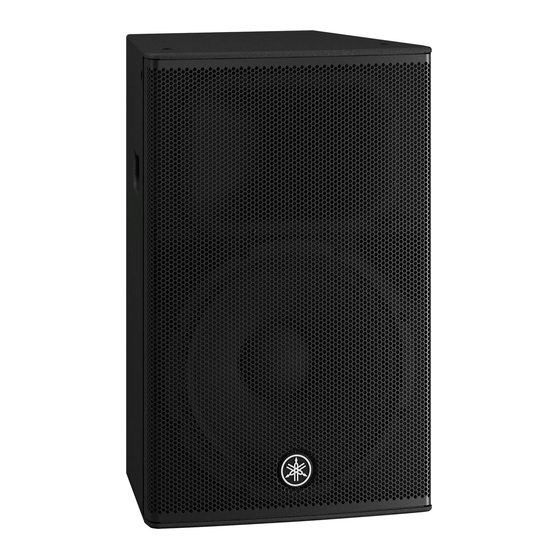
- Page 1 DHR Series POWERED SPEAKER SYSTEM Owner’s Manual Manuale di istruzioni Benutzerhandbuch Руководство пользователя Mode d’emploi Manual de instrucciones Manual do Proprietário...
- Page 2 “ON” , please try to eliminate the problem by using one of the tained in this manual, meets FCC requirements. Modifications not following measures: expressly approved by Yamaha may void your authority, granted by the FCC, to use the product. Relocate either this product or the device that is being affected by the interference.
-
Page 3: Precautions
Location and connection compatible. Please check with your Yamaha dealer. • Check the electric plug periodically and remove any dirt or • Do not place the product in an unstable position or a location dust which may have accumulated on it. - Page 4 Do not leave condensation on the wood; wipe malfunction, or even fire. immediately with a soft cloth. • Always consult qualified Yamaha service personnel if the • If there is reason to believe that condensation might have product installation requires construction work.
-
Page 5: Table Of Contents
Introduction Thank you for purchasing the Yamaha DHR series Powered Loudspeaker. These products are designed for live performance, sound reinforcement and fixed installation sound system applications. This manual explains how to install, set up, and configure the connections for the installers, constructors, or general users familiar with speakers. -
Page 6: Controls And Connectors
Controls and Connectors Rear q Input jacks (CH1 and CH2) w [MIC/LINE] switch These are balanced combo jacks that support both XLR Set this switch to [MIC] or [LINE] for the CH1 jack, and phone plugs (both CH1 and CH2), and RCA pin depending on the level of the input signal. - Page 7 Turn off the power before you connect or discon- nect the power cord. return to normal operation. If the unit does not return to normal operation, please contact your Yamaha dealer. !5 [ / ] (power) switch o [POWER] indicator...
- Page 8 Controls and Connectors Rear Rear (DHR15) (DHR10) Bottom Side (DHR12M) FRONT 7° 0° Bottom !6 Screw holes for U-bracket M8 (DHR10 only) !8 Pole socket For installing with the separately sold U-brackets. This socket adapts to commercially available speaker stands and speaker poles of 35 mm diameter. !7 Screw holes for eye bolts M10 (DHR15 and DHR10 only) Tiltable pole socket (DHR15 only)
-
Page 9: Setup Examples
NOTE We recommend to use Yamaha DXS18 as a subwoofer. In this case, we recommend that the DHR15’s HPF cutoff frequency and the DXS18’s LPF cutoff frequency are set to the same settings; however, you can adjust it as desired. - Page 10 Setup Examples Floor monitor system—using the DHR12M This system is suitable for a performer’s monitoring system. For use as a vocal monitor, set the [D-CONTOUR] switch to [MONI- TOR]. If necessary, you can additionally connect up to four speakers in parallel. In this case we recommend that the signal is input to CH1 and the output switch is set to [CH1 THRU].
- Page 11 Fixed installations—using the DHR10 DHR10 can be neatly installed on a ceiling or a wall, either horizontally or vertically, with the separately sold Yamaha UB- DXRDHR10 U-bracket. For instructions on installing the U-bracket, refer to the corresponding manual for the UB-DXRDHR10.
- Page 12 Setup Examples Rotatable Horn (DHR10 only) Using a No. 2 Phillips head screwdriver, remove all fixing screws on the grille, and remove the grille from the speaker. Using a No. 2 Phillips head screwdriver, remove all screws installed on the horn and pull the horn out from the speaker. NOTE Make sure not to push the screws too strongly with the Phillips head screwdriver.
-
Page 13: Installation Examples
• Make sure to use eye bolts according to the standards and safety regulations in your area. Yamaha cannot be held responsible for damage or injury caused by insufficient strength of the support structure or improper installation. Suspended Installation Using Eye Bolts (DHR15 and DHR10 only) Attach commercially available long eye bolts (30–50 mm in length) to the screw holes located at the top (two locations) and on... -
Page 14: Troubleshooting
Set the [MIC/LINE] switch to the [MIC] position. low. Low and high frequency are Lower the input level or the output level until the [LIMIT] indica- The output limiter is active. unbalanced. tor lights occasionally. If any specific problem should persist, however, please contact your Yamaha dealer. -
Page 15: General Specifications (English Only)
General Specifications (English only) General Specifications General DHR15 DHR12M DHR10 System Type 2-way, Bi-amp Powered Speaker, Bass-reflex Type Frequency Range (-10 dB) 44 Hz–20 kHz 55 Hz–20 kHz 52 Hz–20 kHz Coverage Angle H90° × V60° H90° × V90° H90° × V60° (Rotatable) Crossover Type FIR-X tuning... - Page 16 * Der Inhalt dieser Bedienungsanleitung gilt für die neuesten technischen Daten zum Zeitpunkt der Veröffentlichung. Um die neueste Version der Anleitung zu erhalten, rufen Sie die Website von Yamaha auf und laden Sie dann die Datei mit der Bedie- nungsanleitung herunter.
- Page 17 Block Diagram 电路图 INPUT Combo (Balance) LEVEL SIGNAL D-CONTOUR Amp. Limiter Mute (HF) 120Hz FOH/MAIN 1 (MIC/LINE) MIC/LINE 100Hz FIR-X ●LIMIT ●PROTECTION Combo (Balance) MONITOR LEVEL Amp. Delay Limiter Mute (LF) (CH1+2 MIX) 2 (LINE) Output Temp. DC-fault Current OUTPUT Integral Output On/Off...
- Page 18 Dimensions 外形尺寸 DHR15 2×M10 Unit: mm 単位:mm DHR12M Unit: mm 単位:mm...
- Page 19 Dimensions DHR10 2×M10 2×M8 Unit: mm 単位:mm...
- Page 21 Information for users on collection and disposal of old equipment: This symbol on the products, packaging, and/or accompanying documents means that used electrical and elec- tronic products should not be mixed with general household waste. For proper treatment, recovery and recycling of old products, please take them to applicable collection points, in accordance with your national legislation.
- Page 22 Información para usuarios sobre la recogida y eliminación de los equipos antiguos Este símbolo en los productos, embalajes y documentos anexos significa que los productos eléctricos y electróni- cos no deben mezclarse con los desperdicios domésticos normales. Para el tratamiento, recuperación y reciclaje apropiados de los productos antiguos, llévelos a puntos de reciclaje correspondientes, de acuerdo con la legislación nacional.
- Page 24 Yamaha Pro Audio global website http://www.yamahaproaudio.com/ Yamaha Downloads https://download.yamaha.com/ Manual Development Group © 2021 Yamaha Corporation Published 04/2021 2021年4月 发行 POIN - A1 VDK0300...