
Related Manuals for Dobot MOOZ-2 PLUS

Summary of Contents for Dobot MOOZ-2 PLUS
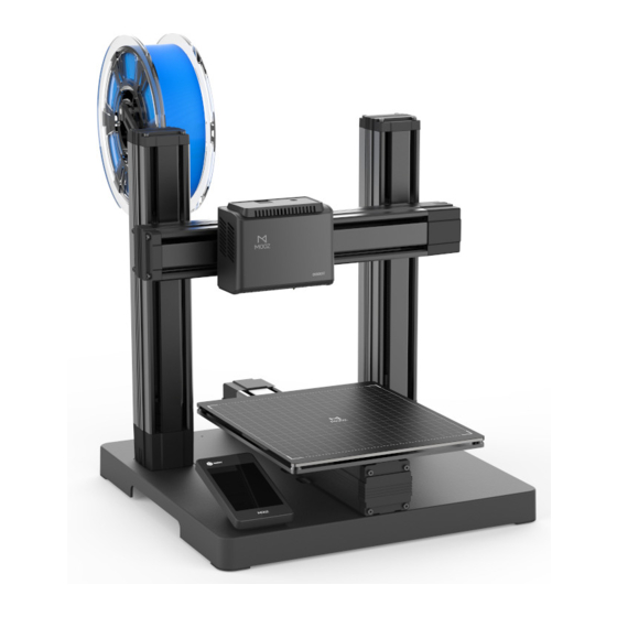
- Page 1 深圳市越疆科技有限公司 -2 PLUS INDUSTRIAL GRADE TRANSFORMABLE METALLIC 3D PRINTER V1.0 2020-07...
-
Page 3: Table Of Contents
Note: Updated Firmwares, User Manuals, Softwares and Tutorial Videos will be uploaded to our official website www.dobot.cc constantly, please use them for better experience. Any support, please contact us: mooz@dobot.cc. -
Page 4: I.operation Panel
Operation Panel 1.1 Home Page 1.2 Calibration Page 3-Point Leveling Interface Calibrate Automatic levelling 调平 Manual levelling Control Tools Interface X: 20 Y: 20 Z: 20 Entrance to zero point setting File Directory Interface interface Calibration Tool 0.06 mm 1 mm 10 mm Auto Level Manual Level... -
Page 5: Print Functional Module Control Interface
1.5 3D Print Functional Module Control Interface 1.6 Laser Engraving Functional Module Control Interface Set nozzle preheat target temperature Set heated bed preheat target temperature Display current laser intensity Preheat nozzle: For testing whether Tool Tool the nozzle heating is normal, press LASER again to stop heating Laser intensity adjustment +/-:... -
Page 6: X/Y/Z Motion Control Interface
1.9 X/Y/Z Motion Control Interface 1.10 Working Process Control Interface Display execution progress of Control motion of X/Y/Z axis linear current file actuators, the corresponding operations Display time elapsed will not change any settings Printing 移动 Display current coordinates Model1.gcode X: 20 Y: 20 Z: 20... -
Page 7: Printing
3D Printing 2.1 3-Point Leveling-Manual levelling Please follow the guide of the machine to record three different points to define a plane parallel to the heated bed, these three points must be recorded in order with nozzle in the areas shown in the drawing below, one in each. The calibration requires to be set only for the first use. Operation steps: 校准... -
Page 8: Set The Zero Point
2.2 Set the Zero Point Zero point is the start point for the machine to print, which requires to be set only for the first use.Operation steps: 校准 校准 Zeroing Zeroing X: 20 Y: 20 Z: 20 X: 20 Y: 20 Z: 20 Fine Tune: 0 mm... -
Page 9: Use The Slicing Software
2.3 Use the Slicing Software Description: MOOZ supports most third-party printing softwares, such as Cura, Repetier-Host, etc. Cura 3.1.0 is described here as an example. 2.3.1 Install the Slicing Software Operation steps: ① Double-click to install the software: Cura3.1.0.exe ② Select the installation directory. It is recommended to keep the ③... - Page 10 G28 X0 Y0 Z0 G92 E0 Back Finish Cancle Note: Origin of MOOZ-2 PLUS is defaulted at left-bottom corner of the heated bed, so do not check the “Origin at center” box, otherwise the model will be printed outside of the heated bed.
-
Page 11: Features
2.4 Features Profile the model: ① Adjust the model: left click on the model, four options “ ”, “ ” , “ ” and “ ” will appear on the left side of the interface, and you can adjust as needed. ②... - Page 12 Description of key profile settings: Quality Layer Height Layer Height: Line Width For the height of each layer of printing, smaller value will produce finer surface, but cost more printing time. Suggested range is 0.05 to 0.3, not exceeding Support Line Width 3/4 of the diameter of the nozzle.
-
Page 13: Offline Printing
2.5 Offline Printing Warning: After printing started, please make sure the first layer is in good bonding condition, and sort out the filament before leaving. Loose bonding may cause falling off of the model, and result in clogging of the print head. “Raft” build plate adhesion type is suggested for better bonding and easy removal of finished model. 2. -
Page 14: Printing Control
2.6 Printing Control Printing Control 1.Speed Control: Change printing speed in real-time. Note that too high speed may sacrifice accuracy and service life of themachine. 2. Process Control—Pause/Continue: Press to pause the printing process, press again to continue. Change filament: If the filament is about to run out, please click Change filamen button. The current process will be paused and the old filament will be aborted. -
Page 15: Power-Loss Resume
2.7 Power-Loss Resume In case of abrupt power failure during printing, the machine will save current printing process and move the functional module away from the print. You may resume or cancle the process after power recovery. Resume Unfinished mission detected ! ! Description Confirm to continue/cancle/skip? Continue: Resume the unfinished printing process... -
Page 16: Laser Engraving
Laser Engraving Warning Protective Shield No Touch Note: Please be sure to wear the goggles and use the protective shield for safety! 3.1 Fix the Workpiece and Replace the Functional Module Operation steps: Stick a small piece of tape to the bottom of workpiece (traceless double-sided tape is recommended), keeping the edges of the workpiece aligned with grids and adhere it to the heated bed. - Page 17 Zero Setting Zero Setting Zero Setting X: 20 Y: 20 Z: 20 X: 20 Y: 20 Z: 20 X: 20 Y: 20 Z: 20 Fine Tune: 0 mm Fine Tune: 0 mm Fine Tune: 0 mm Home Home Home Home Home Home 0.06 mm...
-
Page 18: Use Software To Generate Gcodes
3.3 Use Software to Generate Gcodes Prerequisites : Computer has downloaded and installed MOOZStudio. The download path is https://www.dobot.cc/downloadcenter/dobot-mooz.html#most-download . Step 1 : Double-click MOOZStudio to enter the software Step 2 : Click Open File to import image. interface., select Laser. -
Page 19: Cnc Carving
CNC Carving Warning Protective Shield No Touch Note: Please be sure to wear the goggles and use the protective shield for safety! 4.1 Install the CNC Platform and Workpiece Warning : Heated bed (including the glass and magnets) is a fragile component, please operate with care! Do not mount and dismount it regularly during daily use. Gently separate the heated bed glass and workbench. -
Page 20: Install The Cnc Bit
4.2 Install the CNC Bit ① Rotate counterclockwise to expand ② Insert the CNC bit into Operation steps: ③ Rotate clockwise to clamp the CNC bit the chuck with the wrench the chuck as far as you can 4.3 Set the Zero Point Operation steps: Similar to laser engraving (Refer to Section 3.2 for details on setting the zero point) Zero point Warning: When setting the zero point, use a small step distance in the end (0.1 / 1mm) so that the CNC bit does not accidentally hit the workpiece. -
Page 21: Use Software To Generate Gcodes
4.4 Use Software to Generate Gcodes Prerequisites : Computer has downloaded and installed MOOZStudio. The download path is https://www.dobot.cc/downloadcenter/dobot-mooz.html#most-download . Step 1: Double-click MOOZStudio to enter the software Step 2 : Click Open File to import image. interface. Select CNC. - Page 22 Step 4 : Click Generate G-code to generate a G-code file. Step 5 : Click Export G-code to save the G-code file to a USB flash drive. File File Open File Open File Generate G-code Generate G-code Export G-code Export G-code Setting Description: ①...
-
Page 23: Wifi Transfer And Usb Control
WiFi Transfer and USB Control 5.1 WiFi Transfer You can transfer a G-code file from PC to MOOZ-2 PLUS via WiFi. Prerequisites: MOOZ-2 PLUS and PC must be in the same LAN segment. Step 1 : Click Setting>WiFi>Router on the Step 2 :... -
Page 24: Usb Control
5.2 USB Control Users can control each axis of MOOZ-2 PLUS, set working origin, or print, etc. on MOOZStudio using USB online function. Prerequisites: MOOZ-2 PLSU and PC have been connected via USB cable Step 1 : Open MOOZStudio, select the serial port, and click Connect. -
Page 25: Troubleshooting
Troubleshooting 6.1 3D Printing Failure Q : Print center is at left-bottom A : Wrong machine setting in slicing software, the “ Origin at center ” box shall not be checked, refer to corner of the heated bed Section 2.3.2. A : 1. - Page 26 A : 1. Unplug the cables, U disk orderly, restart the machine to decide if the failure is caused by corresponding faulty Q : Unable to exit “starting...” component. interface after power up 2. Update the mainboard firmware. 3. Check if green indicator light inside the functional module is on. Update the touch pad firmware if so. A : 1.
- Page 27 Q : Abnormal nozzle temperature A : If the auto-leveling module is installed, the nozzle temperature will display 300, please remove the display: 300℃ auto-leveling module to display the normal temperature. 6.4 Appendix Disassemble 3D print module Step 1 : Remove the print head housing after Step 2 :...
- Page 30 This equipment should be installed and operated with a minimum distance of 20cm between the radiator & your body. This transmitter must not be co-located or operating in conjunction with any other antenna or transmitter. All RF frequencies are not restricted in EU member states FCC ID: 2AHI4-MOOZ-2-PLUS 214-106455 www.dobot.cc...
Need help?
Do you have a question about the MOOZ-2 PLUS and is the answer not in the manual?
Questions and answers