
Subscribe to Our Youtube Channel
Related Manuals for Cloos QINEO


Summary of Contents for Cloos QINEO
- Page 1 OPERATING INSTRUCTIONS QINEO CHAMP -En- This is a translation of the original operating instructions. WP-L - 02/19 - Rev.1.1 Keep for future use...
- Page 2 Carl Cloos Schweisstechnik GmbH Carl-Cloos-Strasse 1 35708 Haiger GERMANY Telephone +49 (0)2773 85-0 Telefax +49 (0)2773 85-275 E-mail info@cloos.de www.cloos.de...
- Page 3 EU declaration of conformity No. CMM0516QNCH_01 Product description: MIG/MAG welding machine Model name: QINEO CHAMP, QINEO CHAMP PRO, WD Serial number: Refer to the nameplate on the back of the device Manufacturer: CARL CLOOS Schweisstechnik GmbH Address: Industriestrasse 22-36...
-
Page 5: Table Of Contents
Safety precautions in daily operation ..................Environmental circumstances ..............27 Storage ..............................Transport .............................. Qualification of users ..................28 Block 2 Basic information Qineo Champ Pro Connection overview welding power source ..........30 Connection overview optional interfaces ..........32 Connection overview QWD- M4..............33 Connection overview QWD-A4..............33 Product description ..................34... - Page 6 MAIN - Function ....................53 DuoPulse ............................... CleanStart ............................. Blow through ............................Wire forward ............................Wire backward ........................... Gas manually ............................Start manually............................ MAIN - Progr. (Programming) ...............55 Parameters in the operating modes 2-cycle and 4-cycle ..........Parameters in the operating mode Super-4-cycle .............. Parameters in operating mode Spot Welding / Interval ..........
- Page 7 Technical data ....................126 Weight ..............................Dimensions ............................Ambient conditions ........................Compatibility list ..........................QINEO Wire Drive M4 .................. 127 Connection overview M4 ......................QINEO Wire Drive A4 ................... 129 Structure and function A4 ......................QINEO Wire Drive AR4 ................131 Connection overview AR4 ......................
- Page 8 Commissioning .................... 135 Safety instructions for commissioning ................6.1.1 Risks due to mechanical hazards .................... 6.1.2 Risks due to electrical hazards ....................Reducing insert ..........................6.2.1 Disassembly reducing insert QWD-M .................. Installation/change of the wire drive rollers ..............6.3.1 QWD-M ............................... Inserting the welding wire ......................
- Page 9 3.3.1 QIROX robots ............................ 3.3.2 QINEO welding power sources ....................Job programming QINEO welding power sources ............3.4.1 Select operating mode "Tandem" ................... 3.4.2 Adjustment of the synergy variant ..................3.4.3 "Active QWD" setting ........................Pulse synchronisation ................. 178 Configuration ...........................
-
Page 11: Block 1 Operational Safety
Operational safety Block 1 Operational Safety... -
Page 12: Foreword
DIN ISO 9001 and who put great emphasis on development, manufacture and quality of their products. The power sources and the accessories in the QINEO series have been developed, designed and manufactured according to the generally accepted safety regulations. This is confirmed by the declaration of conformity and CE marking. -
Page 13: Safety Symbols In This Document
Operational safety 2. Safety symbols in this document INFO! INFO! Practical tips and other useful information! ATTENTION! ATTENTION! The signal word indicates a hazard without risk of a physical impairment, which, if not avoided, can lead to property damage. CAUTION! CAUTION! Describes a probably dangerous situation which may result in minor injury or damage to property. -
Page 14: Safety Specifications For Mig/Mag Welding Machines
3. Safety specifications for MIG/MAG welding machines Connection, service and repair works must only be carried out WARNING! by qualified personnel who have the appropriate professional training and sufficient experience and knowledge of the power source and who are able to perform the required works in accordance with the relevant safety specifications. -
Page 15: Application As Directed
Operational safety 3.2 Application as directed The welding machine is exclusively intended for application as directed. The welding machine must only be used for welding processes and working ranges scheduled on the power sign. Every other regarded not directed. The manufacturer is not liable for damages occurred hereof. The power source must never be used for the following works: CAUTION! • Thawing of pipe lines... - Page 16 In practice, various models of active implants are used, the threshold values of which depend on different parameters (type of implant, operating mode, programming of the implant). As far as the occupational safety is concerned, an individual risk assessment is recommended in each individual case. If this is not possible, the generally valid safety values - which are based on the most sensible implants - can be applied, according to standard EN DIN VDE 0848-3-1 "Safety in electric,...
- Page 17 Operational safety 3.3.4. Gases and vapours • All metal vapours are harmful to health! CAUTION! • Be careful with alloys which contain lead, cadmium, cop- per, zinc, nickel, chrome and beryllium. • Chloric cleaning and degreasing agents can lead to the WARNING! formation of the toxic gas phosgene due to the decompo- sition in the arc (risk of suffocation!).
-
Page 18: Electrical Danger Due To Mains Current And Welding Current
Confined spaces must have a free passage allowing escape in case of danger. Please observe the weld area and its surroundings when welding has finished. Fire may break out later due to smouldering. 3.3.6. Noise • Noise may cause permanent damage to your hearing. Dur- ing welding the admissible noise level might be exceeded under unfavourable conditions. - Page 19 Operational safety 3.4.2. Mains connection The power supply must be installed by qualified personnel INFO! only! CAUTION! Please ensure that the mains voltage to be used is identical to the operating voltage indicated on the machine type plate. According to the connection regulations the machine has to be fused and connected by means of a mains cable.
- Page 20 For welding power sources with multiple connection, CAUTION! observe the corresponding wiring on the main and control ...
- Page 21 A second person should be present for safety reasons if working on voltage-carrying parts is required. The side panels and covers of the QINEO series are earthed ATTENTION! by means of screws and toothed conical spring washers.
- Page 22 3.4.4. Stray welding currents Under certain conditions, so-called stray welding currents DANGER! may occur during welding. They may cause the following: Overheating of components which are connected to the workpiece: Fire risk! Destruction of protective conductors (Danger to life!). Damage of power source and other electrical equipment. The two following figures show an example of the conditions for stray welding currents, see Figure 4 and Figure 5.
- Page 23 Operational safety Figure 5. with grounded electronic tools 1 = Welding power source, 2 = Electric tool, 3 = Workpiece 1, 4 = Workpiece 2 The welding current flows via the protective conductors of the CAUTION! two electric tools, if by mistake welding takes place on tool 4 without having changed connections (earth) of the welding current return line from workpiece 3 to workpiece 4 .
-
Page 24: Particular Dangers When Mig/Mag Welding
3.5 Particular dangers when MIG/MAG welding In daily welding practice there are particular danger spots for the user because of the power source configuration and the MIG/MAG welding process. Keep hands, hair, clothes and tools away from moving parts WARNING! such as: • Toothed wheels • Fans... -
Page 25: Safety Precautions In Daily Operation
• Only use the original coolant of the manufacturer if liquid cooled power sources are concerned. • Only the original coolant is suitable for the CLOOS power sources because of its properties such as electric conduc- tivity, antifreeze compound, material compatibility, protec- tion against corrosion and inflammability. - Page 26 If the air entrance ports of the power source are provided with ATTENTION! air filter mats, it should be considered that the duty cycle of the power sources reduces in dependence of the increasing degree of soiling of the air filter mat. The cleaning interval for the air filter mat must be determined as experience shows because the pollution of the filter mat depends on the ambient conditions.
-
Page 27: Environmental Circumstances
Operational safety 4. Environmental circumstances • The mounting area should be free of dust and aggressive agents. • The ground should be horizontal and flat (admissible incli- nation angle max. 10º). • The distance between power source and environment should at least be 0.50 m to allow the cooling air to circu- late unhindered. -
Page 28: Qualification Of Users
5. Qualification of users Only persons who have been trained and instructed on the machines in the QINEO series and who have the required qualifications are permitted to carry out work on CLOOS shielding arc welding machines. The manufacturer is not liable for damage to property or INFO! persons caused by unqualified personnel. -
Page 29: Block 2 Basic Information Qineo Champ Pro
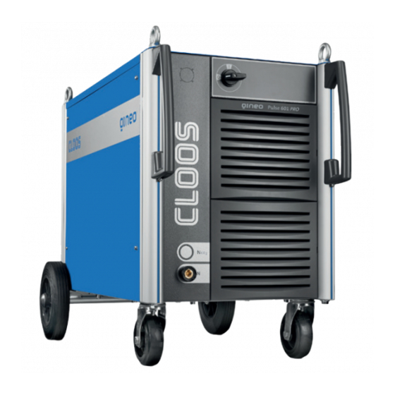
Block 2 Basic information Qineo Champ Pro... -
Page 30: Connection Overview Welding Power Source
CHAMP Pro 1. Connection overview welding power source Power switch Operating module Connection socket Negative cable Figure 6. Front view QINEO Champ Pro... - Page 31 Welding current bushing Connection designations, see chapter 2. ext. Cooling, optional Tandem, optional Coolant supply and return Mains connection Seam tracking Maintenance access Pump Coolant drain cock Inspection window coolant Coolant filler neck Figure 7. Rear view QINEO Champ Pro...
-
Page 32: Connection Overview Optional Interfaces
System plug for: Periphery / CAN (X7) Seam tracking (X33) Gas nozzle sensor (X34) OMI (X70) Tandem / Pulse synchronisation (X32) Qineo Pulse Pro Qineo Champ Pro Standby for external cooling (X40) DeviceNet (X74) ProfiBus (X72) ProfiNet (X73) To guarantee compatibility with old devices: Seam tracking (X33) On request. -
Page 33: Connection Overview Qwd- M4
3. Connection overview QWD- M4 Torch cable assembly connec- tion (here: EURO connection) Torch cooling flow Torch cooling return Wire inlet Welding current connection Quick coupling cooling return Quick coupling cooling flow Quick coupling gas Socket to control line Optional connection RC module 4. -
Page 34: Product Description
The power sources are provided with an external wire drive unit (QINEO Wire Drive). The installation of the wire coil (D300) is easy and functional. The wire coil support is designed for commercial coils (max. 15 kgs). The PREMIUM... - Page 35 PREMIUM operating module The PREMIUM operating module is equipped with a LCD display and offers comfortable and extensive possibilities to display and change all possible functions of the power source. The DuoPulse function can be selected with the Premium operating module. This function enables to generate a 2nd parameter set.
-
Page 36: Commissioning
Optionally, an Euro connection or a Dinse connection can be supplied. The machine has an optional CAN interface to operate/ interrogate various functions in the automation technology. The QINEO CHAMP Pro can be equipped with a weld data monitoring module. 6. Commissioning Assembly A complete machine includes: 1. - Page 37 The shielding gas quantity depends on the process and material and ranges between 8 and 16 l/min. If the Qineo Champ Pro is connected to a central gas supply system (closed circular pipeline), the reducing insert (bore hole 0.6 mm) in the gas valve must be removed.
- Page 38 CHAMP Pro The wire can also be transported by pressing the torch trig- WARNING! ger; in this case, the wire electrode and the contact tip are energised by the complete open-circuit voltage! The wire is also voltage-free in operating mode External. The pressure roller clips (arms) must only be sufficiently pressed against the pressure unit as is necessary for the relevant wire type and size.
- Page 39 Coolant The coolant can be filled in the cooling system after having connected the welding torch. Always use a coolant approved by CLOOS! It is not allowed CAUTION! to use chlorinated or mineral water because of its electrical conductivity. Via filler neck the coolant is filled into the storage tank. The tank can be filled up to approx.
-
Page 40: Shutdown / Recycling
CLOOS Schweisstechnik participates on an authorised Waste Disposal and Recycling System and is recorded under number WEEE - Reg. No. DE 83919745 in the Register of Old Electronic Appliances. Returns can be made to CLOOS directly or to any CLOOS sales partner throughout Europe. -
Page 41: Technical Data
8. Technical data CHAMP 451 Pro CHAMP 601 Pro Type: QINEO CHAMP Pro Ambient conditions Operating temperature °C -10°C…+40°C Storage temperature °C -25°C…+55°C 50% at 40°C Humidity 90% at 20°C Free of unusual dust Ambient air Free of aggressive media Welding range 40A/16V-450A/36.5V... - Page 42 CHAMP Pro...
-
Page 43: Block 3 Premium Operating Module
Block 3 PREMIUM operating module Contents Operating controls .................. 45 Main menu ....................46 MAIN - Synergy ..................47 MAIN - Op. (operating modes) .............. 47 2-cycle ..........................47 4-cycle ..........................48 Super 4-cycle ......................49 Spot welding ......................49 External ........................49 MAIN process .................... 50 Electrode ........................50 TIG ..........................50 Speed Pulse .......................50... - Page 44 10.1 Config - General ......................72 10.1.1 Display brightness .....................72 10.1.2 MHW 405 TQ ......................72 10.1.3 Control coolant pump and fan..............73 10.2 Config - General (2) ....................73 10.3 Config - General (3) ....................74 10.3.1 Config - General - Basic settings ..............74 10.3.1.1 Config - General - Basic settings - Tandem ..........76 10.3.1.2 Config - General - Sense technology ............76 10.3.1.3 Config - General - QWD ...................77...
-
Page 45: Operating Controls
1. Operating controls The PREMIUM operating module with its enhanced range of functions meets the most demanding requirements for a practice-oriented, conveni- ent operation. A 320 x 240 pixel LCD colour display with function buttons on the side enables simple operation even when programming extensive welding tasks. -
Page 46: Main Menu
Main menu 2. Main menu In the main menu (MAIN) you can call the following functions by means of the function keys F1-F8: MAIN (1) active MAIN (2) active MAIN (3) active Function Page Function Page Function Page Weld data moni- F1 Synergy Page 47 F1 Configuration... -
Page 47: Main - Synergy
3. MAIN - Synergy Processes Normal, S-Pulse, Pulse etc. according to characteristic curve data set Material Fe, CrNi1.4316, AlSi, AlMg, AlMg4,5 Mn, CuSi, CuAl, Fe Basis, Fe Rut, Fe Wire 0.6; 0.8; 0.9; 1.0 ;1.2 ;1.4 ;1.6; 2.0; 2.4 (mm) 82 % argon, 18 % CO2 91 % argon, 4 % O2, 5 % CO2 92 % argon, 8 % CO2... -
Page 48: 4-Cycle
MAIN - Op. (operating modes) 4.2 4-cycle Operating mode 4-cycle is provided for longer manual welds. 1st cycle --> Press torch trigger • Solenoid valve for shielding gas opens • Welding voltage is applied on wire electrode • Wire drive unit starts with reduced speed (inching-in) •... -
Page 49: Super 4-Cycle
4.3 Super 4-cycle Operating mode Super-4-cycle is provided for longer standard manual welding tasks. The detailed operating possibilities are described in chapter "7. MAIN - Progr. (Programming)". 1st cycle --> Press torch trigger • Solenoid valve for shielding gas opens •... -
Page 50: Main Process
MAIN process 5. MAIN process 5.1 Electrode All commercially available stick electrodes can be welded in conjunction with the "Electrode" process. If the "Electrode" process is selected, "Aset" appears in the display. The displays for wire diameter and material thick- ness are masked out. -
Page 51: Syn Off
5.6 Syn off In this process, you set the parameters wire speed (rotary knob 1) and welding voltage (rotary knob 2) manually. All other basic data and second- ary parameters are provided by the synergy characteristic curve. 5.7 Processes with the appendix CW (Cold Weld) Processes with the appendix CW are welding processes in connection with INFO! A/C power technology. -
Page 52: Normal Cw
MAIN process 5.7.2 Normal CW This is a MIG/MAG welding process without pulse but with synergy func- tion. The welding current depends on the distance between torch and workpiece. In connection with the QIROX robot application, arc seam track- ing is possible to a limited extent. This welding process is suitable for sheet thicknesses from 0.5 mm - 3.0 mm. -
Page 53: Main - Function
Funktionen 6. MAIN - Function The display field is highlighted yellow if one function is active. INFO! F U N K T I O N E N Clean Start Puls 4 -Takt Funktionen 1.2 mm 82% Argon 18% Co Figure 10. Menu functions 6.1 DuoPulse F U N K T I O N E N If the function is active, a second welding parameter is generated from the... -
Page 54: Wire Forward
MAIN - Function Funktionen Funktionen Funktionen 6.4 Wire forward F U N K T I O N E N F U N K T I O N E N Funktionen With this function the wire feed is switched on manually. F U N K T I O N E N This function is only active as long as the button is pressed. -
Page 55: Main - Progr. (Programming)
7. MAIN - Progr. (Programming) The welding power source always uses the existing synergic characteristic curves. The values for all secondary parameters, including "CleanStart", are already preset in the synergy characteristic curves. Activate the "Programming" function to enter the programming mode. In this menu the default values can be adjusted. - Page 56 MAIN - Progr. (Programming) The correction value is entered by means of the rotary knob 3. The changed parameters are saved simultaneously and do not have to be saved addi- tionally. During the Job mode, the job has to be saved again! If you did not save the INFO! correction values in a job, the settings of the last selected characteristic curve are lost!
-
Page 57: Parameters In The Operating Modes 2-Cycle And 4-Cycle
7.1 Parameters in the operating modes 2-cycle and 4-cycle Function Correction value Gas pre-flow Off, +/- 99 Inching-in +/- 99 Start program (time) Off, +/- 99 Start program (power) +/- 99 Upslope Off, +/- 99 Main power Absolute value (m/min) DuoPulse modulation* (+/- 99) DuoPulse frequency*... - Page 58 MAIN - Progr. (Programming) Step modulation The welding practice often requires working with different main param- eters. The power continuation is ensured by shortly pressing the torch trigger (< 0.5 sec). Use the function "Step modulation" to determine the step width of the increase or the reduction of the wire speed or power per keystroke (Step).
-
Page 59: Parameters In Operating Mode Spot Welding / Interval
7.3 Parameters in operating mode Spot Welding / Interval If the operating mode "Spot welding" is active, you have to enter the values for the parameters "Spot welding time" and "Pause time" (sec). Function Correction value Gas pre-flow Off, +/- 99 Inching-in +/- 99 Start time... -
Page 60: Setting Ranges
MAIN - Progr. (Programming) 7.4 Setting ranges Setting ranges can be defined for starting power, main power and end crater power. Prerequisite for configuring the setting ranges is the "Access management" or the optional "User management", see section "10.6 Access rights" on page 83. -
Page 61: Prerequisite To Use The Setting Ranges
Stellbereiche In der Serienversion werden Min und Max getauscht !! Max oben After pressing the key "Setting range", the following appears. S T E L L B E R E I C H Stell- bereich Hauptleistung 4.0 m/min 6.5 m/min - 10 Dyn. - Page 62 Display Zugangsverwaltung Optionen MAIN - Progr. (Programming) Zugangsverwaltung - Optionen Bedienlevel > > Automatik < < Schweissen freigeben Job speichern sperren Job aufrufen freigeben Handrad Leist/Fein freigeben Puls 4 -Takt 1.2 mm 82% Argon 18% Co Figure 18. "Config"- "Access management" - "Options" menu Once the setting ranges have been configured and activated, the message "LIMIT"...
-
Page 63: Deactivating The Setting Ranges
Stellbereiche 7.4.3 Deactivating the setting ranges In der Serienversion werden Min und Max Select the "Progr." function from the "MAIN" page. Use the arrow keys to getauscht !! Max oben Stellbereich Aus select the appropriate start, main or end crater power. The display shows the "Setting range"... -
Page 64: Expert Mode" (Single Parameter Mode)
MAIN - Progr. (Programming) 7.7 "Expert Mode" (single parameter mode) The "Expert Mode" is an alternative operating possibility to the synergy mode. The "Expert Mode" requires a fundamental knowledge of the pulsed arc welding process and is only recommended for users having a good experience in welding. -
Page 65: Secondary Parameters In The "Expert Mode
Always use rotary knob 1 to set the wire speed. Use rotary knob 2 to set the most important electrical parameters depend- ing on the process. Depending on the selected process, the parameters voltage, frequency or the arc length are selected. Use rotary knob 3 to select further welding relevant parameters depending on the process. -
Page 66: Duopulse Parameters" In The "Expert Mode
MAIN - Progr. (Programming) 7.7.3 "DuoPulse parameters" in the "Expert Mode" DuoPulse is not an independent pulsed arc welding process but only a INFO! changing between two parameter settings. If the "Expert Mode" function is active, the "DuoPulse parameters" function is available for the start, main and end program in the "PROGRAMMING"... -
Page 67: Main - Measured Values
8. MAIN - Measured values In the "Measured values" menu, the most important welding relevant values are displayed. Hold Hold Hold Hold Leistung Leistung Leistung Betriebs Betriebs Pulsspannung Pulsspannung Pulsspannung daten daten Grundspannung Grundspannung Grundspannung Puls 4 -Takt Puls 4 -Takt 1.2 mm 1.2 mm 82% Argon 18% Co... -
Page 68: Data Set Switching 1/2
MAIN - Measured values Use the arrow keys to switch between the individual input points. After entering the data you can quit the menu by means of the "Esc" key. For orientation purposes please find below some welding wire weights. These weights may vary in practice and have to be checked by means of a precision balance for an exact determination of the weight. -
Page 69: Seam Counter Setup
Display Messwerte Betriebsdaten B E T R I E B S D A T E N Kosten Summenzähler Setup sätze Betriebszeit 12:47 Std Schweisszeit 10:17 Std Aktuelle Naht 12.4 Sek Datensatz Verbrauchsdaten ab Reset - 1 - umschalt Schweissnähte Schweisszeit 0.0 Sek Draht 0.00 m... -
Page 70: Consumption Costs
MAIN - Display Display Messwerte Verbrauchskosten (x.11) 8.1.3 Consumption costs This function shows the costs for the number of weld seams, wire, gas and energy. B E T R I E B S D A T E N Kosten Summenzähler Setup sätze Betriebszeit... - Page 71 M A I N M A I N C - Start C - Start Synergie Synergie Progr. Progr. m / min m / min Betr. Betr. Messwerte Messwerte Blechdicke Blechdicke 8.5 mm 8.5 mm ASet ASet 230 A 230 A VSet VSet 27.9 V...
-
Page 72: Main (2) - Config (Configuration)
MAIN (2) - Config (Configuration) 10. MAIN (2) - Config (Configuration) From the MAIN(1) display, you can access the MAIN(2) display by pressing the "-->" key. Then press the "Config" function. 10.1 Config - General Use the arrow symbols to switch between the individual menu items. Konfig - Allgemein Konfig - Allgemein Displayhelligkeit im Standby... -
Page 73: Control Coolant Pump And Fan
Function Description Using this function, you set the speed of the parameter Interval change released by the torch trigger. The adjustment is between 1 … 10. The correction value is 100 ms each. Using this function, you set the size of the parameter change released by the torch trigger. -
Page 74: Config - General (3)
MAIN (2) - Config (Configuration) In this menu item you can: • Select the dimension display for the wire speed. • Select whether the display shows the process voltage (terminal voltage Display Konfig Allgemein (3) ab V10 minus values of the external welding current circuit = calculated volt- age at the workpiece) or the terminal voltage (voltage at the welding power source). - Page 75 In this menu, the basic settings for the use of the welding power source are made. Start/End program in 2-cycle mode For welding applications it is often not required to use start and end crater programs (e.g. frequent spot welding). Therefore, you have the option to switch off this function.
-
Page 76: Config - General - Basic Settings - Tandem
MAIN (2) - Config (Configuration) Fine adjustment variant This menu item offers the "Arc fine adjustment" by means of a synergy characteristic curve or the wire speed. Name Function • With this setting the arc length is corrected via the adaptation of the wire speed. -
Page 77: Config - General - Qwd
In this menu you configure which PushPull drive is connected to which wire drive (QWD1 ... QWD4). • No drive • Cloos Arcette • Cloos Arcette 2 • Binzel PP+401D • TBI PPP 7G/7W • Dinse DIX MPZ 304 •... -
Page 78: Config - General - Sd Module
Release Pulse, ExpertMode, Operating data, Push-Pull systems etc., see Figure 36. If you intend to activate an additional option, CLOOS Schweisstechnik will provide a new 16 digit activation code. - Page 79 Enter this activation code after activating the "Activation code" function and confirm with "Enter". If all information is correct, the newly activated option is listed in the "Activated options" overview. Figure 37. Config Activation code If an error occurred during the transmission or input of the activation code, the error message "317 Wrong activation code!"...
-
Page 80: Config - Water Monitoring
MAIN (2) - Config (Configuration) 10.4 Config - Water monitoring The water monitoring is inactive if no sensors are available or the pump is ATTENTION! switched off, see chapter 10.1.3 on page 73. Use the arrow symbols to switch between the individual menu items. Konfig -Wasserüberwachung Konfig -Wasserüberwachung Wasserüberwachung... -
Page 81: Config - Compensation
In case of an error an error message is shown on the display mask. This message can be hidden by means of the "Esc" key. If the error cause is not remedied, the error message will be shown again after 10 sec. The menu is quit by shortly pressing rotary knob 3! Wasserdurchfluss niedrig! - Page 82 MAIN (2) - Config (Configuration) Konfig - Kompensation Konfig - Kompensation Schweißkreis Schweißkreis Gesamt- Kabellänge (m) Gesamt- Kabellänge (m) T- Anpassung T- Anpassung (ms) (ms) 0.38 0.38 Puls 4 -Takt Puls 4 -Takt Puls 4 -Takt 1.2 mm 1.2 mm 1.2 mm 82% Argon 18% Co 82% Argon 18% Co...
-
Page 83: Access Rights
Display Konfig Kompensation (ab V.10) Konfig - Kompensation Schweißkreis Widerstand R [mOhm] Induktivität L [wH] 14.4 Mess- Kompensation-MSG Normal Vorgang freigeben Mess- Vorgang starten Puls 4 -Takt 1.2 mm 82% Argon 18% Co Figure 41. Compensation of the welding current circuit from version x.10 on The determined values can be re-adjusted manually if necessary. - Page 84 MAIN (2) - Config (Configuration) Configurator The user with the "Configurator" operating level can call and look at the in- dividual functions. He has an active access right to all preset values includ- ing access to the synergy characteristic curves. The user must register with an 8-digit code number.
-
Page 85: Config - User Management And Pak (Option)
"Access code" line. With the aid of the code number it is possible to decode the password by calling the CLOOS Service Hotline. You can now enter again the code num- ber. 10.6.2 Config - User management and PAK (option) - Page 86 MAIN (2) - Config (Configuration) information saved in the welding power source. The respective user profile is then activated in the welding power source. If a user logs in who is new for the welding power source, the access is either denied or his user profile is transferred into the user management and stored, depending on the setting.
-
Page 87: Config - User Management - Options
Auto log off of configurator Name Function The user with the "Configurator" operating level is Off (default) not logged off automatically. The user with the "Configurator" operating level … min. is logged off automatically after a preset time (1min … 30min). If no input is made via the operating module during the preset time INFO! period, the access state is reset to the preset "Operating level after switch... -
Page 88: Config - User Management - User Overview
MAIN (2) - Config (Configuration) Call up a Job Name Function Enable You can call jobs without login. You can only call jobs after login with your password Lock or PAK. Rotary knob In this menu item you can select the following functions: Name Function Enable Power /... - Page 89 Create/edit new user Push rotary knob 3 to select a free storage space in the user overview and to save all relevant user data in the "Config - Edit user" menu. Delete user Konfig – Benutzer Editieren Passwort 000000 Benutzername Mustermann Speichern Erlaubter Jobbereich...
-
Page 90: Config - User Management - User Overview - Pak
MAIN (2) - Config (Configuration) 10.6.2.3 Config - User management - User overview - PAK A PAK can only save one user profile. INFO! If you save another user on an already allocated PAK, the first user will get lost. You can save the created/selected users to a PAK using the "Program PAK"... -
Page 91: Config - Pc Adaptation
10.7 Config - PC adaptation An Ethernet interface is used to connect the welding power source to the QDM (Qineo Data Manager) software. For the communication of the weld- ing power source within the network, the IP address and the subnet mask must be set. -
Page 92: Config - Process Monitoring
MAIN (2) - Config (Configuration) 10.9 Config - Process monitoring Arc existing process control If the signal "Arc existing" is not active for more than 1 second during the welding process (process phase), the error message "Err. 23 Arc failure pro- cess phase"... -
Page 93: Main (2) - Diagnostics
11. MAIN (2) - Diagnostics The diagnostics menu provides the following submenus: • Status of the cooling system. • Query of the power class and the software versions. • Input / output occupancy of different functions. • Status on the QWD (Wire Drive). •... -
Page 94: Diagnostics Cooling
MAIN (2) - Diagnostics 11.1 Diagnostics Cooling In menu cooling the current functional state of the water pump and the fan can be visualised. The symbols for the pump and the fan are high- lighted in yellow when the components are in operation. As for the coolant pump, the flow quantity and the coolant temperature are shown as well (for wire drive units with water sensors). -
Page 95: Diagnostics I / 0 (Inputs And Outputs)
Figure 55. Menu diagnostics inputs/outputs The I/0 menu offers a very convenient way of displaying the signal states of the inputs and outputs on the Qineo. 10 inputs and 10 outputs each are available. The user/service technician is free to assign these inputs and outputs in order to initiate certain situations and signal states. -
Page 96: Diagnostics Vbc Module
MAIN (2) - Diagnostics Select signals Use rotary knob 3 to select a signal place for an input or output in the I/0 menu (1-10). Press the rotary knob to change to the selection mode. The storage space is highlighted in green. Select the appropriate input or output by turning the rotary knob. -
Page 97: Diagnostics Qwd
ProfiNet IO 2 Status Firmware V0.00.00 IP-Adresse 000.000.000.000 Subnetzmaske 000.000.000.000 QINEO – EIN/Ausgangsbytes Eingang Ausgang Puls 4 -Takt 1.2 mm 82% Argon 18% Co Figure 57. Premium Diagnostics ProfiNet 11.5 Diagnostics QWD The QWD menu offers a convenient way of displaying the most important signal states in the wire drive unit. -
Page 98: Diagnostics Pc Adaptation
MAIN (2) - Diagnostics Diagnose PC-Anpassung 11.6 Diagnostics PC adaptation The MAC address, the IP address and the subnet mask of the welding power source are displayed in this menu. D I A G N O S E - PC Anpassung Ethernet –... -
Page 99: Diagnostics Pulsed Arc Synchronisation
Diagnose Impulssynchronisation 11.8 Diagnostics pulsed arc synchronisation Taktgeber The synchronisation mode of the welding power source is shown in this menu. Diagnose - Impulssynchronisation Synchronisation-Modus Taktgeber Frequenz 200 Hz Phasenverschiebung 50 % Taktgeber aktiv Synchronisation aktiv Puls 4 -Takt 1.2 mm 82% Argon 18% Co Figure 61. - Page 100 MAIN (2) - Diagnostics Diagnose Systemlogbuch S Y S T E M L O G B U C H 3/9999 Datum TT.MM.JJJJ Uhrzeit HH:MM:SS Name Logbuch Auswahl Doku-Nr. Details Puls 4 -Takt X 1000 Handrad 1.2 mm 82% Argon 18% Co Figure 62.
-
Page 101: Diagnostics Robot (From X.11.30 On)
11.9.1 Diagnostics Robot (from x.11.30 on) This menu displays the communication state between connected robot and welding power source. The following values are displayed: Version Shows the software version of the robot controller. It is differentiated between protocol version 1 and protocol version 2. -
Page 102: Main (2) - Language
MAIN (2) - Language 12. MAIN (2) - Language For different languages 4 storage places are available in this menu. The factory setting for the first 3 storage places is allocated to the languages German, English and French. The user is free to allocate the 4th storage place to any language required. -
Page 103: Main (2) - Data Backup
13. MAIN (2) - Data backup In the "Data backup" menu, so-called jobs can be written from the welding power source to the SD memory card or from the SD memory card to the job memory of the welding power source. Insert the SD memory card into the card slot below rotary knob 3. -
Page 104: Read Job From Sd Memory Card
MAIN (2) - Data backup 13.2 Read job from SD memory card All jobs on the SD memory card are displayed. Read in a single job Use rotary knob 3 to select the job to be saved and confirm the selection by pressing rotary knob 3 (Enter function). -
Page 105: User Log On/Off
INFO! ber appears below the "Access code" line. With the aid of the code number it is possible to decode the password by calling the CLOOS Service Hotline. You can now enter the code number again. 14.2 MAIN (2) - Log off If the "Log-off"... -
Page 106: Job Mode
3. J O B – S P E I C H E R N J O B – S P E I C H E R N Job -10 Job -10 CLOOS Innovation CLOOS Innovation CLOOS Innovation Löschen Löschen Querträger 8569... -
Page 107: Overwrite An Existing Job
Functions on the left side: Function name/symbol Functional description Left arrow key Cursor moves one position to the left Capital letters and special characters Switch between upper and lower case Small letters and special characters letters Numbers and special characters Functions on the right side: Function name/symbol Functional description... -
Page 108: Activate Job
Job mode 15.4 Activate job To activate existing jobs, shortly press the "Job" button. You are now in Job selection mode. All available jobs are listed on the dis- play. Select the job to be activated by means of rotary knob 3. Press the job button again or the rotary knob 3 to activate the selected job. -
Page 109: Block 4 Additional Information
Block 4 Additional information... -
Page 110: Rc Plus (Remote Control)
RC Plus (Remote Control) 1. RC Plus (Remote Control) Quick save memory keys 1…4 Multi-functional key (hold value display, selection actual value display) Selection key Processes Selection key Operating modes Job key (load job, quit job) Display Rotary knob left (capacity adjustment) Rotary knob right (fine adjustment, dynamics) -
Page 111: Mhw 405 Tq (2-Button Torch)
2. MHW 405 TQ Qineo welding power sources can be provided with a remote control on the (2-button torch) welding torch. The connection is made via the remote controller socket at the QWD. Use the configuration menu of the welding power source to determine... -
Page 112: Sd Module
3. SD module Each electronically controlled Qineo welding power source can be equipped with a weld data monitoring system (Exception: For devices of the Qineo NexT series, the SD module is included as standard). If all necessary components are connected to the welding power source, the display of the Premium operating module shows the function "SD... - Page 113 The level of the WCM module changes if the arc is interfered with external influences such as impurities, paint, oil etc. The WCM function is optional. It is not included in the standard scope of supply of the Qineo welding power sources! • Reserve1* / Heat input For this monitoring channel two states are available for selection.
- Page 114 SD module Reserve1* activated: The input signal is rated for a voltage of 0…10 V. The name and the unit are freely selectable. Via the menu item “Factor(10V)” a scaled value can be allocated to the control voltage 10V. For example: 10 volts correspond to a certain sensor signal.
- Page 115 Profi-Bus), it is important that signals of one group are never divided over both modules. This would result in malfunctions. Please contact the department Technical Documentation of Carl Cloos INFO! Schweisstechnik GmbH to get detailed information about the “Qineo Interfaces”.
-
Page 116: Submenus
SD module 3.2 Submenus • Display Change to different views by activating the function. • Apply/Accept set value (during welding) Activate the function to take over the currently measured actual vales as set values to the activated monitoring channels. • Reset / SD special function Use this function to reset all error messages triggered during monitoring. -
Page 117: Configure Monitoring Channel
• Set-up mode On/Off This function is helpful during set-up mode of components because you can change here the parameters without triggering a warning message or error message which would lead to an interruption of the welding process. When the set-up mode is “on”, the following signal outputs are ignored: •... - Page 118 SD module You can select from the following settings for the individual monitoring channels: "Off" Monitoring channel is deactivated. The welding power source sends a message to a master "Message controller for further processing. The master controller group 1” or "2" makes the decision (PLC, robot).
-
Page 119: Logbook
3.4 Logbook A logbook is available in the SD module for the archiving of the weld data. In the “SD monitor” menu you switch to the current logbook display by selecting the “Logbook” function , see Figure 74. 14.12.2010 14.12.2010 L O G B U C H L O G B U C H Uhrzeit: 10:35:47... - Page 120 SD module 13.12.2010 13.12.2010 L O G B U C H L O G B U C H Uhrzeit: 10:35:47 Uhrzeit: 10:35:47 / 11 / 11 Bauteil: Unterbodengruppe Bauteil: Unterbodengruppe Naht: 12 Naht: 12 : 10 ohne Pulse : 10 ohne Pulse Zeit Zeit : 7.8 Sec...
- Page 121 Use the “Error details” function to call up a detailed error description, see Figure 77. 13.12.2010 13.12.2010 F E H L E R F E H L E R Uhrzeit: 10:35:47 Uhrzeit: 10:35:47 Bauteil: Unterbodengruppe Bauteil: Unterbodengruppe Naht: 12 Naht: 12 Zeitpkt : 4.8 Sec Zeitpkt : 4.8 Sec Logbuch...
-
Page 122: Combine The Application Example Sd Monitoring With Qirox Controller
SD module 3.5 Combine the application example SD Settings on the robot controller monitoring with QIROX 1. Program the list call up by means of “Digital program selection” in the controller weld parameter lists of the robot. 2. The command FUNCON SDSTOPCP must be programmed in the robot's sequence program to ensure that the QIROX robot controller reacts to the SD signals of the welding power source. - Page 124 SD module...
-
Page 125: Block 5 Qineo Wire Drive
Block 5 Qineo Wire Drive Contents 1. Technical data Weight ......................126 Dimensions ....................126 Ambient conditions ................... 126 Compatibility list ..................126 2. QINEO Wire Drive M4 Connection overview M4 ................. 128 3. QINEO Wire Drive A4 Structure and function A4 ..............130 4. -
Page 126: Technical Data
50% at 40°C Information on spare parts and consumables as well as circuit diagrams of the individual wire drives and wire feed units can be found in the spare parts documentation for the QINEO welding power source. 1.4 Compatibility list Qineo... -
Page 127: Qineo Wire Drive M4
2. QINEO Wire Drive M4 The supporting design of the QINEO Wire Drive Metal consists of a stable sheet steel housing. The corners are provided with 4 aluminium profiles to stiffen the housing. The interior of the wire drive unit is accessible via a stable cover which is fastened on the housing body by means of solid hinges. -
Page 128: Connection Overview M4
QINEO Wire Drive M4 2.1 Connection overview M4 Torch cable assembly connection Torch cooling flow Torch cooling return Wire inlet Welding current connection Quick coupling cooling return Quick coupling cooling flow Quick coupling gas Socket to control line Optional connection RC module... -
Page 129: Qineo Wire Drive A4
3. QINEO Wire Drive A4 The QINEO Wire Drive A was specially developed for industrial robot ap- plications. Options: • EURO, DINSE connection • Weld data monitoring • CLOOS Duo Drive (CDD) • Wire end control Installation kit A4: •... -
Page 130: Structure And Function A4
QINEO Wire Drive A4 3.1 Structure and function A4 Torch cable assembly connection (here: EURO connection) "Blow out" connection (for EURO connection) Torch trigger connection (for SZ connection) MCU connection Connection for collision protec- tion, gas nozzle sensor etc. CDD/MD connection Button "Gas manually"... -
Page 131: Qineo Wire Drive Ar4
4. QINEO Wire Drive AR4 The QINEO Wire Drive AR has been specially developed for mounting on or at the shoulder joint of industrial robots. This ensures an optimum welding wire feed especially in the field of hollow shaft robots. Despite the comprehensive equipment with different sensors for weld data monitoring it is characterised by a low weight and a small size. -
Page 132: Connection Overview Ar4
QINEO Wire Drive AR4 4.1 Connection overview AR4 Torch cable assembly connection Button "Wire forward" Button "Gas manually" Button "Wire backward" CDD connection Connection for collision protec- tion, gas nozzle sensor etc. Connection nipple "blow out" (optional) Torch cooling flow... -
Page 133: Function
5. Function 5.1 Button "Gas manually" For all welding power sources of the QINEO series the button "Gas manu- ally" is designed as a switch. The gas valve remains open if the button is actuated and released again. The gas valve is closed by pressing the button again. -
Page 134: Button "Wire Forward" Or "Wire Backward
Function Press the button "Gas manually" INFO! again to stop the gas flow. 5.2 Button "Wire forward" or "Wire backward" If one of these buttons is pressed, the wire feed motor switches on and accelerates from 1 m/min to 7 m/min in 3 seconds. The welding wire is fed forward or backward. -
Page 135: Commissioning
6. Commissioning 6.1 Safety instructions for commissioning The QINEO Wire Drive must not be operated if it has visible damage or ATTENTION! defects, which may lead to a hazard: • Prior to commissioning the wire drive unit, check to see if the wire guide, the connection line and the casing are damaged. -
Page 136: Reducing Insert
Commissioning 6.2 Reducing insert In all wire drive units the gas-solenoid valve is provided with a mechanical reducing insert having a bore of Ø0.6mm. This insert adapts the gas flow rate at the litre scale of the pressure reducer on the gas cylinder. In the case that a company is working with a central gas supply (inlet pres- sure 6 …... -
Page 137: Installation/Change Of The Wire Drive Rollers
6.3 Installation/change of the wire drive rollers Stab injury! WARNING! In the case of an incorrect handling of the welding torch during the wire feeding process, the wire transport may cause stab injuries on hand, eyes or the face. During the wire feeding, you should always keep the welding torch in a position turned away from the body! •... - Page 138 Commissioning...
-
Page 139: Inserting The Welding Wire
6.4 Inserting the welding wire Stab injury! WARNING! In the case of an incorrect handling of the welding torch during the wire feeding process, the wire transport may cause stab injuries on hand, eyes or the face. During the wire feeding, you should always keep the welding torch in a position turned away from the body! •... - Page 140 Commissioning The wire inlet must not touch INFO! the wire drive roller. ...
-
Page 141: Adjustment Of The Pressure Clamps
Risk of electric shock WARNING! If unrestricted access to the live single parts of the QINEO Wire Drive is possible, all persons must exercise caution to prevent electric shock or risks of electrical energy. -
Page 142: Maintenance
Prior to each start of the QINEO Wire drive please check: • The correct mounting of the current tip. • The correct mounting of the gas nozzle. • The screw connection of the torch cable assembly at the QINEO Wire Drive. • The correct fixing of the drive rollers. -
Page 143: Error List
8. Error list Error Cause Help Nest formation of the wire. Faulty welding wire feed. Remove the welding wire and insert a new one. Drive rollers slip and/or the weld- Wrong pressure adjustment at the Correct the pressure adjustment. ing wire feed is too slow or does pressure clamps. -
Page 144: Disposal And Recycling
When using oils and greases make sure that these substances do not RECYCLING harm the paint. CLOOS assumes no liability of any kind for damages that result from the use of unsuitable consumables! When handling oils and greases, the safety regulations for the product... -
Page 145: Block 6A Error Messages
Block 6a Error messages... -
Page 146: Error Messages
1. Error messages M A I N M A I N M A I N M A I N M A I N C - Start C - Start C - Start Synergie Synergie Synergie Synergie Synergie Progr. Progr. Progr. Progr. -
Page 147: Error List
1.1 Error list Error message on the Possible cause Remedy display Check plug and connections to the Interruption of CAN bus between operating module CAN connection faulty control and operating module Service Switch machine Off and On Error when loading Operating module cannot call up Check cable connections the job data of the... - Page 148 Error message on the Possible cause Remedy display An unknown or invalid power class Switch machine Off and On 16 Unknown power class was detected. (valid are: 350A, 450A Service or 600A) Operating instructions Weld blocking of No enable from access operating module management.
- Page 149 Error message on the Possible cause Remedy display Check cable connection between Error charging circuit on Service charging circuit and control Tronic Pulse computer. Zero point adjustment cannot be Switch machine Off and On Calibration error executed. Values too high. Internal Inverter Service check failed.
- Page 150 Error message on the Possible cause Remedy display Software update Software version VBC Software update required. DeviceNet out-of-date Service Switch machine Off and On VBC DeviceNet module Communication between control Check plug and connections (CAN BUS) failed and DeviceNet module faulty. Service Switch machine Off and On VBC DeviceNet bus...
- Page 151 Error message on the Possible cause Remedy display Switch machine Off and On Check plug and connections 58 IO module 2 failed CAN connection interrupted. Service Switch machine Off and On VBC Profibus module Check plug and connections CAN connection interrupted. failed Service Software version...
- Page 152 Error message on the Possible cause Remedy display Operating module Language file version newer than Use other language file - Maximum text machine (not compatible with number in language file Service software). exceeded Operating module Language file version newer than Use other language file - Invalid symbol in machine (not compatible with...
- Page 153 Error message on the Possible cause Remedy display Check SD card Timeout during data Check plug and connections Error in data transfer. receipt Service Call up logbook file again SD module - Required Logbook deleted. logbook not found Service Check SD settings SD module Logbook is Start welding process No data available in the logbook.
- Page 154 Error message on the Possible cause Remedy display Software update QWD4 No controller Error occurs with push/pull torches. data available Software out-of-date. Service Check ribbon cable connection from the control to the output stage 254 QWD1 Wrong coding Wrong coding of motor type. Service Check ribbon cable connection from the 255 QWD2 Wrong coding...
- Page 155 Error message on the Possible cause Remedy display Check motor movement Check CDD Check wire feed distance Preset rotation speed not reached. Check CDD cable connections CDD2 Desired rotation Encoder signals faulty motor Check encoder speed not reached movement. Fuse 42V supply faulty Power supply board Service Check motor movement...
- Page 156 Error message on the Possible cause Remedy display Check wire feed distance Overload results in increased 275 QWD2- Overcurrent current load of the drive unit. Service Check wire feed distance Overload results in increased 276 QWD3- Overcurrent current load of the drive unit. Service Check wire feed distance Overload results in increased...
- Page 157 Error message on the Possible cause Remedy display Create new user 336 Invalid data set number Error when creating user. Service Wrong check sum from Create new data set Error in user data set. user data set Set up a new PAK Enter a new password User management- Password entered already in use.
- Page 158 Error message on the Possible cause Remedy display Check software version Software version Software out-of-date, minimum Software update QWD-B2.2 out-of-date V1.00.00 Service 711 QWD-B2.2 failed Check software version Software version Software out-of-date, minimum Software update QWD-B3.2 out-of-date V1.00.00 Service 713 QWD-B3.2 failed Check software version Software version Software out-of-date, minimum...
-
Page 159: Block 6B General Maintenance Instructions
Block 6b General maintenance instructions... -
Page 160: Maintenance And Care
1. Maintenance and Care... -
Page 161: Regular Testing
Danger of injury from electric shock DANGER! Cleaning/maintenance works at a device which is not disconnected from the electrical power supply may lead to severe injury or even death. • Maintenance work on electrical components may only be carried out by specialist electricians. -
Page 162: Semi-Annual Testing
Control Remedy Weekly The perfect function of the operating interface, signal and Contact a qualified electrician. control LEDs. Damage to the housing. Replace damaged housing parts. The tightness, damages, buckling or pollutions of the coolant Attach/change the coolant hoses. hoses. Clean the coolant hoses. -
Page 163: Special Testing
In the case of light pollution, use compressed air to clean the filter mat. If the filter mat is very dirty, change it. Only use original CLOOS parts. ATTENTION! 1.4.2 Crane suspensions at the wire drive unit Check the crane suspensions for damages once a month. -
Page 165: Block 7 Automation
Block 7 Automation... -
Page 166: Interfaces
(control voltage 0-10 V) with digital technology. In the case of the Qineo Pulse A, the Profibus DP is used for the transmis- sion of control signals (process data) between the power source and the periphery (PLC) or the robot controller. -
Page 167: Profinet Module
The terminating resistors have a value of 120 Ohm. 1.5 Ethernet-IP Module The Ethernet/IP Gateway is a slave with which QINEO power sources can be connected to an Ethernet/IP field bus. So master controllers such as robots or PLC can be controlled. -
Page 168: Qirox Technology Interface (Qti)
2. QIROX Technology Interface (QTI) 2.1 Software compatibility Depending on the software version of the QINEO welding power source, a distinction is made between protocol type 1 and protocol type 2. • QINEO welding power sources with a software version lower than X.11. -
Page 169: Basic Configuration Operating Mode "Tandem
3. Basic configuration Operating mode "Tandem" 3.1 Connection diagram This connection diagram shows how to connect two welding power sources, the robot controller and several wire drive units to a changing system with a Tandem and single wire torch. QINEO- X8-2 Splitter X8-1 Type A... -
Page 170: Pre-Adjustments
CAN interface, the following entry in the welding parameter list is re- quired: "FUNCON WPS, 1". Only the following parameters are available in the welding parameter list of the QIROX robot to control the QINEO welding power sources: • Selection of the welding power source type (welding power source number 3711): "QINEO PULSE/CHAMP TANDEM (CAN)"... - Page 171 Depending on the application, the following menu items must be consid- Display Konfig, Grundeinstellung ab V.12 ered in the "Config" --> "General" --> "Basic settings" menu, see figure. Konfig - Grundeinstellungen Werksein- Start-/Endprogramm im 2 Takt stellungen Start-/Endeprogramm zurück Externe Ansteuerung Anzahl Leitspannungen Tandem Ext.
-
Page 172: Job Programming Qineo Welding Power Sources
3.4 Job programming QINEO welding power sources 3.4.1 Select operating mode "Tandem" At the Master machine, and only there, different operating modes can be INFO! selected for the Tandem process. M A I N C - Start Synergie Program- mieren m / min Betr. - Page 173 Programmieren - Tandem Tandem - Betriebsart Tandem Nahtsuchsignal Quelle Master- Gerät Puls 4 -Takt 1.2 mm 82% Argon 18% Co Operating mode "Tandem" Name Function Tandem operation: The two welding power sources weld, "Tandem" the two gas valves open, the two arcs are monitored, the two welding power sources are monitored.
-
Page 174: Adjustment Of The Synergy Variant
Tandem welding. In the "Synergy variant" menu you determine the synergy characteristic curves to be welded by the Qineo welding power source. If Tandem synergy characteristic curves are available in the combination of process, material, wire and gas, one "Tandem leading" variant is available for the wire in front, and a second "Tandem following"... -
Page 175: Active Qwd" Setting
S ynergie - Variante Standard Tandem führend Tandem folgend S- Puls Extern Job 201 TANDEM 2 S- PULS ALTERN. 1.2 mm 92% Argon 8% Co S- Puls Extern Job 201 Synergy variant Name Function The synergy characteristic curve has been developed for "Standard"... - Page 176 P R O G R A M M I E R E N Expert Stell- Startleistung bereich Mode - 0 - Dyn. 6.0 m/min Aktiver Tandem Puls 4 -Takt Impuls- 1.2 mm Sync. 82% Argon 18% Co Programmieren – Aktiver QWD Aktiver QWD QWD-Nummer Puls 4 -Takt...
- Page 177 In the menu "Programming - Active QWD" you determine which QWD is actuated by the welding power source. Programmieren – Aktiver QWD Aktiver QWD QWD-Nummer Puls 4 -Takt 1.2 mm 82% Argon 18% Co Name Function "QWD number" The welding power source activates QWD1…4 for 1…4 welding.
-
Page 178: Pulse Synchronisation
4. Pulse synchronisation Pulse synchronisation means the time synchronisation of two or more pulse currents. The pulses are synchronised to constantly reduce the unavoidable mutual interference to a level as low as possible. The pulses of the welding power sources can be configured as follows: •... -
Page 179: Synchronisation Mode
Programmieren 4.1.1 Synchronisation mode Impulssynchronisation - Taktgeber Programmieren – Impulssync. Synchronisations-Modus Taktgeber Phasenverschiebung Alternierend Puls Extern Job 101 PULS ALTERN. 1.2 mm 82% Argon 18% Co Name Function The pulse cycle of the welding power source is "Pulse generator" available for synchronisation. The welding power source executes its pulses at the "Pulse receiver"... -
Page 180: Phase Shift
4.1.2 Phase shift The pulse phases [f , … f ] of as many welding power sources as desired can now be synchronised with each other. Programmieren Impulssynchronisation - Taktgeber Programmieren – Impulssync. Synchronisations-Modus Taktgeber Phasenverschiebung Alternierend Puls Extern Job 101 PULS ALTERN. - Page 181 a1) Synchronous [ f With this adjustment all pulse phases [f … f ] of the welding power sources involved are executed synchronously. "Pulse generator (f )" - "Pulse receiver (f )" synchronous. a2) Synchronous 1/2 [ ½ f With this adjustment the pulse phase [f …...
-
Page 182: Job Allocation
5. Job allocation The selected welding parameters are determined as so-called "jobs" and saved in the welding power sources. The determination in jobs allows to change them at will. It is recommended to assign the job numbers according to a previously INFO! fixed definition. - Page 183 • "Tandem mode" with only one wire in the Tandem torch ("Tandem- Single Wire") A wire drive unit of the master or the slave welding power source is used depending on the application. The corresponding job selection is sufficient, here 112, 113 or 212, 213. Select in the adjustments which wire is welded with which synergy characteristic curve.
- Page 186 www.qineo.de...
Need help?
Do you have a question about the QINEO and is the answer not in the manual?
Questions and answers