
Related Manuals for SMC Networks LECSN-T Series


Summary of Contents for SMC Networks LECSN-T Series
- Page 1 Doc no. LEC*-OMY0102 PRODUCT NAME AC Servo Motor Driver (Network card type) MODEL/ Series LECSN-T□ Series...
- Page 2 LECSN2-T□ Series / Driver 1. Safety Instructions These safety instructions are intended to prevent hazardous situations and/or equipment damage. These instructions indicate the level of potential hazard with the labels of “Caution,” “Warning” or “Danger.” They are all important notes for safety and must be followed in addition to International Standards (ISO/IEC), *1) and other safety regulations.
- Page 3 Note that the CAUTION level may lead to a serious consequence according to conditions. Please follow the instructions of both levels because they are important to personnel safety. What must not be done and what must be done are indicated by the following diagrammatic symbols. Indicates what must not be done.
- Page 4 LECSN2-T□ Series / Driver 1. Safety Instructions Caution The product is provided for use in manufacturing industries. The product herein described is basically provided for peaceful use in manufacturing industries. If considering using the product in other industries, consult SMC beforehand and exchange specifications or a contract if necessary.
- Page 5 1. To prevent electric shock, note the following WARNING Before wiring and inspections, turn off the power and wait for 15 minutes or more until the charge lamp turns off. Then, confirm that the voltage between P+ and N- is safe with a voltage tester and others. Otherwise, an electric shock may occur.
- Page 6 4. Additional instructions The following instructions should also be fully noted. Incorrect handling may cause a fault, injury, electric shock, etc. (1) Transportation and installation CAUTION Transport the products correctly according to their mass. Stacking in excess of the specified number of product packages is not allowed. Do not hold the front cover when transporting the driver.
- Page 7 (2) Wiring CAUTION Perform wiring correctly and securely. It may cause unexpected movement of the servo motor. Do not attach a phase-advancing capacitor, surge killer, or radio noise filter (FR-BIF manufactured by Mitsubishi Electric Corporation) to the output side of the driver. Connect the driver and servo motor power phases (U, V, W) correctly, as this may cause the servo motor to malfunction.
- Page 8 (4) Usage CAUTION Provide an external emergency stop circuit to ensure that operation can be stopped and power switched off immediately. Do not disassemble, repair, or modify the equipment. Before resetting an alarm, make sure that the run signal of the driver is off in order to prevent a sudden restart.
- Page 9 (6) Maintenance, inspection and parts replacement CAUTION It is recommend that the driver be replaced every 10 years when it is used in general environment. (7) General instruction To illustrate details, the equipment in the diagrams of this Instruction Manual may have been drawn without covers and safety guards.
- Page 10 CONTENTS 1. FUNCTIONS AND CONFIGURATION 1- 1 to 1-23 1.1 Summary ............................. 1-2 1.2 Function block diagram ........................1-3 1.3 Driver standard specifications ......................1-7 1.4 Combinations of driver and servo motors ..................1-10 1.5 Function list ............................1-11 1.6 Model designation ..........................1-14 1.7 Structure ............................
- Page 11 3.8.2 Detailed explanation of interfaces ....................3-27 3.8.3 Source I/O interfaces ........................3-29 3.9 Servo motor with a lock ........................3-30 3.9.1 Safety precautions ........................3-30 3.9.2 Timing chart ..........................3-31 3.9.3 Wiring diagrams (LE-□-□ series servo motor) ................3-37 3.10 Grounding............................
- Page 12 6.1 Different adjustment methods ......................6-2 6.1.1 Adjustment on a single driver ......................6-2 6.1.2 Adjustment using setup software (MR Configurator2TM) .............. 6-3 6.2 One-touch tuning ..........................6-4 6.2.1 One-touch tuning flowchart ......................6-5 6.2.2 Display transition and operation procedure of one-touch tuning ............ 6-6 6.2.3 Caution for one-touch tuning ......................
- Page 13 10. CHARACTERISTICS 10- 1 to 10-8 10.1 Overload protection characteristics ....................10-2 10.2 Power supply capacity and generated loss ..................10-3 10.3 Dynamic lock characteristics ......................10-5 10.3.1 Dynamic lock operation ......................10-5 10.3.2 Permissible load to motor inertia when the dynamic lock is used ..........10-6 10.4 Cable bending life ..........................
- Page 14 13.1.4 Residual risks of the STO function ..................... 13-3 13.1.5 Specifications ..........................13-4 13.1.6 Maintenance ..........................13-5 13.2 STO I/O signal connector (CN8) and signal layouts ............... 13-5 13.2.1 Signal layouts ..........................13-5 13.2.2 Signal (device) explanations....................... 13-6 13.2.3 How to pull out the STO cable ....................13-6 13.3 Connection example ........................
- Page 15 17.4.1 Station JOG operation ......................17-14 17.4.2 JOG operation .......................... 17-16 18. EtherCAT COMMUNICATION 18- 1 to 18- 206 18.1 EtherCAT COMMUNICATION ....................18-3 18.1.1 Summary ..........................18-3 18.1.2 Function list ..........................18-6 18.1.3 Communication specifications ....................18-9 18.1.4 Communication specifications ..................... 18-10 18.1.4.1 Communication status ....................
- Page 16 18.5.4.9 Homing mode (hm) ......................18-56 18.5.4.10 Point table mode (pt) ..................... 18-84 18.5.4.11 Jog mode (jg) ........................ 18-89 18.5.4.12 Indexer mode (idx) ......................18-96 18.5.5 Touch probe ........................18-103 18.5.6 Quick stop .......................... 18-107 18.5.7 Halt ............................. 18-108 18.5.8 Software position limit ......................
- Page 17 19.1.2 Function list ..........................19-4 19.1.3 Communication specifications ....................19-6 19.1.4 Establishing and disconnecting the communication .............. 19-7 19.1.4.1 Communication status ...................... 19-7 19.1.4.2 Startup ..........................19-8 19.1.4.3 Network disconnection procedure ..................19-9 19.1.5 Summary of object library ...................... 19-9 19.1.5.1 Section definition of Drive Configuration Object (64h) ............
- Page 18 19.6.2.1 Summary ......................... 19-85 19.6.2.2 Reading instruction codes ....................19-85 19.6.2.3 Writing instruction code ....................19-86 19.6.2.4 Variable mapping ......................19-88 19.6.2.5 Respond code ......................... 19-89 19.6.3 Stroke end ..........................19-90 19.6.4 Definition of alarm-related objects ..................19-91 19.6.5 Parameter object ......................... 19-92 19.6.5.1 Definition of parameter objects ..................
- Page 19 20.2.1 Specifications ......................... 20-8 20.2.2 Parts identification ........................20-8 20.2.3 LED display ..........................20-9 20.2.3.1 Network Status LED ......................20-9 20.2.3.2 Card Status LED ....................... 20-9 20.2.3.3 Link/Activity LED ....................... 20-9 20.2.4 Ethernet cable connection ....................20-10 20.3 PROCESS DATA (CYCLIC DATA EXCHANGE) ..............20-11 20.4 ACYCLIC DATA EXCHANGE ....................
- Page 20 20.8.11 Halt ............................ 20-113 20.8.12 Ramp Stop ......................... 20-113 20.8.13 PROFIdrive parameter definitions related to alarms ............20-114 20.8.14 Parameter .......................... 20-115 20.8.14.1 Parameter enabling ..................... 20-116 20.8.15 Degree function ......................... 20-117 20.9 OBJECT DICTIONARY ......................20-119 20.9.1 Store parameters ....................... 20-119 20.9.2 PROFIdrive parameter (Manufacturer-specific) list ............
- Page 21 App. 4.7 Transportation and storage ....................App.-14 App. 4.8 Technical data ........................App.-15 App. 4.8.1 LECSN2-T□ driver ...................... App.-15 App. 4.8.2 Driver dimensions ......................App.-15 App. 4.8.3 Mounting hole ........................ App.-15 App. 4.9 Check list for user documentation ..................App.-16 App.
- Page 22 1. FUNCTIONS AND CONFIGURATION 1. FUNCTIONS AND CONFIGURATION ......................2 1.1 Summary ................................2 1.2 Function block diagram ............................3 1.3 Driver standard specifications ..........................7 1.4 Combinations of driver and servo motors ..................... 10 1.5 Function list ..............................11 1.6 Model designation ............................14 1.7 Structure ................................
- Page 23 1. FUNCTIONS AND CONFIGURATION 1. FUNCTIONS AND CONFIGURATION 1.1 Summary To ensure safety of the system against unauthorized access via a network, take CAUTION security measures such as using a firewall. The LECSN□-T□ series general-purpose AC servo has further higher performance and higher functions compared to the previous LECS□-S□...
- Page 24 1. FUNCTIONS AND CONFIGURATION 1.2 Function block diagram The function block diagram of this servo is shown below. (1) LECSN2-T5, T7, T8 (Note 4) Pow er factor improving Regenerative DC reactor option driver Servo amplifier Servo motor Dynamic Diode (Note 1) brake stack Relay...
- Page 25 1. FUNCTIONS AND CONFIGURATION Note 1. The built-in regenerative resistor is not provided for LECSN2-T5. 2. For 1-phase 200 V AC to 240 V AC, connect the power supply to L1 and L3. Leave L2 open. For the power supply specifications, refer to section 1.3.
- Page 26 1. FUNCTIONS AND CONFIGURATION (2) LECSN2-T9 (Note 2) Pow er factor improving Regenerative DC reactor option driver Servo amplifier Servo motor Dynamic Diode brake stack Relay circuit MCCB (Note 1) Current Regene- Pow er encoder rative supply CHARGE lamp Cooling fan Control lock El ectromagnetic...
- Page 27 1. FUNCTIONS AND CONFIGURATION (3) LECSN1-T5, T7, T8 (Scheduled release product) Regenerative option driver Servo amplifier Servo motor Dynami c brake (Note 1) ci rcuit MCCB Charge (Note 2) Current lamp Pow er Regene- encoder supply Relay rative TR Diode stack Control lock Electromagnetic...
- Page 28 1. FUNCTIONS AND CONFIGURATION 1.3 Driver standard specifications Model: LECSN2-T□ 3-phase 170 V AC Rated voltage Rated current Output Output frequency Less than 590 Hz Output frequency accuracy ±0.01% 3-phase or 1-phase 200 V AC to 240 V AC, 50 Hz/60 Hz Voltage/Frequency Rated current 3-phase or 1-phase 170 V AC to...
- Page 29 1. FUNCTIONS AND CONFIGURATION Note 1. 0.3 A is the value applicable when all I/O signals are used. The current capacity can be decreased by reducing the number of I/O points. 2. When closely mounting the drivers, operate them at the ambient temperature of 0 ˚C to 45 ˚C or at 75% or smaller effective load ratio.
- Page 30 1. FUNCTIONS AND CONFIGURATION LECSN1-T□ (Scheduled release product) Rated voltage 3-phase 170 V AC Rated current Output Output frequency Less than 590 Hz Output frequency ±0.01% accuracy Voltage/Frequency 1-phase 100 V AC to 120 V AC, 50 Hz/60 Hz Rated current Permissible voltage 1-phase 85 V AC to 132 V AC fluctuation...
- Page 31 1. FUNCTIONS AND CONFIGURATION Note 1. 0.3 A is the value applicable when all I/O signals are used. The current capacity can be decreased by reducing the number of I/O points. 2. When closely mounting the drivers, operate them at the ambient temperature of 0 ˚C to 45 ˚C or at 75% or smaller effective load ratio.
- Page 32 1. FUNCTIONS AND CONFIGURATION 1.5 Function list The following table lists the functions of this servo. For details of the functions, refer to each section of the detailed description field. POINT Symbols in the network column indicate the following networks. ECT: EtherCAT EIP: EtherNet/IP PNT: PROFINET...
- Page 33 1. FUNCTIONS AND CONFIGURATION Network Detailed Function Description explanation ECT EIP PNT Analyzes the frequency characteristic of the mechanical system by simply connecting an Machine analyzer function Setup software (MR Configurator2 ) installed personal computer and the driver. Setup software (MR Configurator2 ) is necessary for this function.
- Page 34 1. FUNCTIONS AND CONFIGURATION Network Detailed Function Description explanation ECT EIP PNT This amplifier complies with the STO function as functional safety of IEC/EN 61800-5-2. STO function Chapter 13 You can create a safety system for the equipment easily. You can check the cumulative energization time and the number of on/off times of the inrush relay.
- Page 35 1. FUNCTIONS AND CONFIGURATION 1.6 Model designation (1) Rating plate * If I/O connector(CN1) is required, order the part number "LE-CSNS" separately. * If I/O cable(CN1) is required, order the part LECS N 2 - T5 number "LEC-CSNS-1" separately. Motor type Driver type Capacity Encoder...
- Page 36 1. FUNCTIONS AND CONFIGURATION b) I/O Connector (For LECSN□-T□) LE-CSNS Driver Type LECSN□-T□ )/ 10320-52F0-008 ( Shell kit ) of Sumitomo 3M Connector *LE-CSNS is 10120-3000PE ( Limited or equivalent goods. Applicable wire size: AWG24~30 c)Regenerative options LEC-MR-RB-032 Regenerative option Type Permissible regenerative power 30W *MR-RB□...
- Page 37 1. FUNCTIONS AND CONFIGURATION g)STO cable(3m) LEC-MR-D05UDL3M * MR-D05UDL3M of Mitsubishi Electric Corporation. It is a cable that connects the driver with the equipment when the safety function is used. Do not use other cables. h) I/O Connector LEC-CSNS-1 Cable length(L)[m] Driver Type LECSN□-T □...
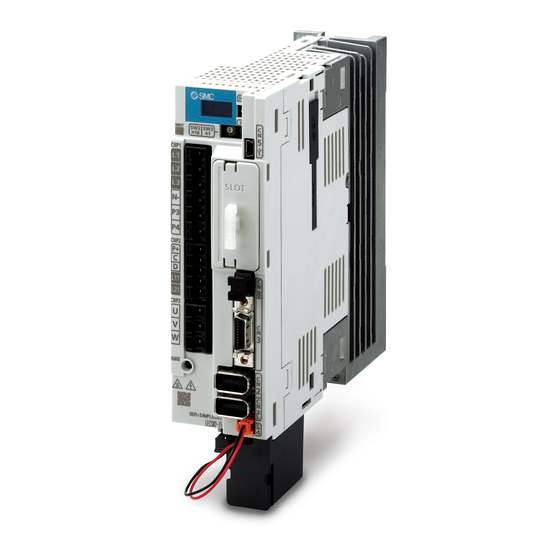
- Page 38 1. FUNCTIONS AND CONFIGURATION 1.7 Structure 1.7.1 Parts identification (1) LECSN2-T□ The diagram is for LECSN2-T5 Detailed Name/Application explanation Display The 3-digit, 7-segment LED shows the servo status and the alarm number. Axis selection rotary switch (SW2/SW3) Section 4.3 Used to set the axis No. of driver. Mode select switch (SW1) Set the test operation mode.
- Page 39 1. FUNCTIONS AND CONFIGURATION (2) LECSN1-T□ (Scheduled release product) The diagram is for LECSN1-T5. Detailed Name/Application explanation Display The 3-digit, 7-segment LED shows the servo status and the alarm number. Axis selection rotary switch (SW2/SW3) Section 4.3 Used to set the axis No. of driver. Mode select switch (SW1) Set the test operation mode.
- Page 40 1. FUNCTIONS AND CONFIGURATION 1.8 Installation and removal of network card Before installing or removing network card, turn off the power and wait for 15 minutes or more until the charge lamp turns off. Then, confirm that the voltage WARNING between P+ and N- is safe with a voltage tester and others.
- Page 41 1. FUNCTIONS AND CONFIGURATION (1) Installation of network card 1) Remove the slot cover with a flat-blade screwdriver, etc. Make sure to store the removed cover. 2) Press the network card against the board on the right side so as to align with the guide in the driver, and insert it along the board.
- Page 42 1. FUNCTIONS AND CONFIGURATION (2) Removal of network card 1) Loosen two screws fixing the network card approximately 5 mm using the #8 6-lobe driver. 5 mm Fixing screw (6-lobe screw ) 2) Hook the slot cover included at product shipment on the loosened screws as shown in the diagram.
- Page 43 1. FUNCTIONS AND CONFIGURATION 1.9 Configuration including peripheral equipment Connecting a servo motor of the wrong axis to U, V, W, or CN2 of the driver may CAUTION cause a malfunction. POINT Equipment other than the driver and servo motor are optional or recommended products.
- Page 44 1. FUNCTIONS AND CONFIGURATION (3) LECSN1-T□ (Scheduled release product) The diagram is for LECSN1-T7. (Note 2) Pow er supply Personal computer Molded-case MR Configurator2 circuit breaker (MCCB) (Note 3) Magnetic contactor (MC) Netw ork module dependence (Note 6) Mitsubishi electric (Note 1) (Note 1) Power factor...
-
Page 45: Table Of Contents
2. INSTALLATION 2. INSTALLATION ..............................2 2.1 Installation direction and clearances ......................3 2.2 Keep out foreign materials ........................5 2.3 Encoder cable stress ..........................5 2.4 Inspection items ............................5 2.5 Parts having service lives ..........................6 2.6 Restrictions when using this product at altitude exceeding 1000 m and up to 2000 m above sea level...7 2 - 1... -
Page 46: Installation
2. INSTALLATION 2. INSTALLATION WARNING To prevent electric shock, ground each equipment securely. Stacking in excess of the specified number of product packages is not allowed. Do not hold the front cover, cable, or connector when carrying the driver. It may fall. -
Page 47: Installation Direction And Clearances
2. INSTALLATION 2.1 Installation direction and clearances The equipment must be installed in the specified direction. Otherwise, it may cause a malfunction. CAUTION Leave specified clearances between the driver and the cabinet walls or other equipment. Otherwise, it may cause a malfunction. (1) Installation clearances of the driver (a) Installation of one driver Cabinet... - Page 48 2. INSTALLATION (b) Installation of two or more drivers POINT Close mounting is possible depending on the capacity of the driver. Refer to section 1.3 for availability of close mounting. When mounting the drivers closely, do not install the driver whose depth is larger than that of the left side driver since CNP1, CNP2, and CNP3 connectors cannot be disconnected.
-
Page 49: Keep Out Foreign Materials
2. INSTALLATION 2.2 Keep out foreign materials (1) When drilling in the cabinet, prevent drill chips and wire fragments from entering the driver. (2) Prevent oil, water, metallic dust, etc. from entering the driver through openings in the cabinet or a cooling fan installed on the ceiling. -
Page 50: Parts Having Service Lives
2. INSTALLATION 2.5 Parts having service lives Service lives of the following parts are listed below. However, the service lives vary depending on operation and environment. Part name Life guideline Smoothing capacitor 10 years Number of power-on, forced stop by EM1 (Forced stop 1), and quick stop command from controller: Relay 100,000 times... -
Page 51: Restrictions When Using This Product At Altitude Exceeding 1000 M And Up To 2000 M Above Sea Level
2. INSTALLATION 2.6 Restrictions when using this product at altitude exceeding 1000 m and up to 2000 m above sea level (1) Effective load ratio and regenerative load ratio As heat dissipation effects decrease in proportion to the decrease in air density, use the product Within the effective load ratio and regenerative load ratio shown in the following figure. - Page 52 3. SIGNALS AND WIRING 3. SIGNALS AND WIRING ..........................2 3.1 Input power supply circuit ........................3 3.2 I/O signal connection example ........................7 3.2.1 For sink I/O interface ...........................7 3.2.2 For source I/O interface ........................8 3.3 Explanation of power supply system ......................9 3.3.1 Signal explanations ...........................9 3.3.2 Power-on sequence ..........................10 3.3.3 Wiring CNP1, CNP2, and CNP3 ....................11...
-
Page 53: Signals And Wiring
3. SIGNALS AND WIRING 3. SIGNALS AND WIRING Any person who is involved in wiring should be fully competent to do the work. Before wiring, turn off the power and wait for 15 minutes or more until the charge lamp turns off. Then, confirm that the voltage between P+ and N- is safe with a voltage tester and others. -
Page 54: Input Power Supply Circuit
3. SIGNALS AND WIRING Connecting a servo motor of the wrong axis to U, V, W, or CN2 of the driver may cause a malfunction. CAUTION Before wiring, switch operation, etc., eliminate static electricity. Otherwise, it may cause a malfunction. 3.1 Input power supply circuit Always connect a magnetic contactor between the power supply and the main circuit power supply (L1/L2/L3) of the driver, in order to configure a circuit that... - Page 55 3. SIGNALS AND WIRING (1) Using 3-phase 200 V AC to 240 V AC power supply for LECSN2-T□ (Note 4) Malfunction Emergency stop sw itch driver Servo amplifier Servo motor MCCB CNP1 (Note 7) (Note 11) CNP3 3-phase (Note 6) 200 V AC to Motor 240 V AC...
- Page 56 3. SIGNALS AND WIRING (2) Using 1-phase 200 V AC to 240 V AC power supply for LECSN2-T□ (Note 4) Malfunction Emergency stop sw itch driver Servo amplifier Servo motor (Note 7) MCCB CNP1 1-phase (Note 11) 200 V AC to CNP3 (Note 6) 240 V AC...
- Page 57 3. SIGNALS AND WIRING (3) LECSN1-T□ (Scheduled release product) (Note 4) Malfunction Emergency stop sw itch driver Servo amplifier Servo motor MCCB CNP1 (Note 7) 1-phase (Note 11) 100 V AC to CNP3 (Note 6) 120 V AC Unassigned Motor Unassigned (Note 10) (Note 1)
-
Page 58: I/O Signal Connection Example
3. SIGNALS AND WIRING 3.2 I/O signal connection example POINT EM2 has the same function as EM1 in the torque mode. 3.2.1 For sink I/O interface driver Servo amplifier 10 m or less 10 m or less (Note 8) (Note 12) (Note 12) (Note 10) Main circuit... -
Page 59: For Source I/O Interface
3. SIGNALS AND WIRING 3.2.2 For source I/O interface POINT For notes, refer to section 3.2.1. driver Servo amplifier 10 m or less 10 m or less (Note 8) (Note 12) (Note 12) (Note 10) Main circuit (Note 3) 24 V DC pow er supply Forced stop 2 DOCOM... -
Page 60: Explanation Of Power Supply System
3. SIGNALS AND WIRING 3.3 Explanation of power supply system 3.3.1 Signal explanations POINT For the layout of connector and terminal block, refer to chapter 9. Connection target Symbol Description (application) Supply the following power to L1, L2, and L3. For 1-phase 200 V AC to 240 V AC, connect the power supply to L1 and L3. -
Page 61: Power-On Sequence
3. SIGNALS AND WIRING 3.3.2 Power-on sequence POINT The output signal, etc. may be unstable at power-on. (1) Power-on procedure 1) Always wire the power supply as shown in above section 3.1 using the magnetic contactor with the main circuit power supply (L1/L2/L3). Configure up an external sequence to switch off the magnetic contactor as soon as an alarm occurs. -
Page 62: Wiring Cnp1, Cnp2, And Cnp3
3. SIGNALS AND WIRING 3.3.3 Wiring CNP1, CNP2, and CNP3 POINT For the wire sizes used for wiring, refer to section 11.9. When wiring, remove the power connectors from the driver. Insert only one wire or ferrule to each wire insertion hole. Use the driver power supply connector for wiring CNP1, CNP2, and CNP3. - Page 63 3. SIGNALS AND WIRING (2) Cable connection procedure (a) Fabrication on cable insulator Refer to table 3.1 to 3.4 for stripped length of cable insulator. The appropriate stripped length of cables depends on their type, etc. Set the length considering their status. Twist strands lightly and straighten them as follows.
-
Page 64: Connectors And Pin Assignment
3. SIGNALS AND WIRING 3.4 Connectors and pin assignment POINT The pin assignment of the connectors is as viewed from the cable connector wiring section. For the STO I/O signal connector (CN8), refer to chapter 13. For the CN1 connector, securely connect the external conductive portion of the shielded cable to the ground plate and fix it to the connector shell. - Page 65 3. SIGNALS AND WIRING The driver front view shown is that of the LECSN□-T7 or less. Refer to chapter 9 DIMENSIONS for the appearances and connector layouts of the other drivers. CN5 (USB connector) Refer to section 11.7 T PR2 For the STO I/O signal connector, refer to section 13.2.
-
Page 66: Signal (Device) Explanations
3. SIGNALS AND WIRING 3.5 Signal (device) explanations For the I/O interfaces (symbols in I/O division column in the table), refer to section 3.8.2. The pin numbers in the connector pin No. column are those in the initial status. 3.5.1 Input device (1) Input device pin The following shows the input device pins and parameters for setting devices. - Page 67 3. SIGNALS AND WIRING Connector Device Symbol Function and application pin No. division Touch probe 1 TPR1 CN3-10 DI-1 The touch probe function is available to latch the current position by sensor input. Turn it on to latch the current position. For the touch probe function, refer Touch probe 2 TPR2 CN3-1...
-
Page 68: Output Device
3. SIGNALS AND WIRING Connector Device Symbol Function and application pin No. division Proportional control Turn PC on to switch the speed amplifier from the proportional integral type to DI-1 the proportional type. If the servo motor at a stop is rotated even one pulse due to any external factor, it generates torque to compensate for a position shift. - Page 69 3. SIGNALS AND WIRING Device Symbol Function and application Limiting speed When the speed reaches the speed limit value in the torque mode, VLC will turn on. When the servo is off, TLC will be turned off. The device cannot be used in the position mode and velocity mode. Zero speed detection ZSP turns on when the servo motor speed is zero speed (50 r/min) or less.
-
Page 70: Output Signal
3. SIGNALS AND WIRING 3.5.3 Output signal Connector Signal name Symbol Function and application pin No. Encoder A-phase CN3-6 These devices output pulses of encoder output set in [Pr. PA15] and [Pr. PA16] in the pulse (differential line differential line driver type. CN3-16 driver) In CCW rotation of the servo motor, the encoder B-phase pulse lags the encoder A-... -
Page 71: Forced Stop Deceleration Function
3. SIGNALS AND WIRING 3.6 Forced stop deceleration function POINT When alarms not related to the forced stop function occur, control of motor deceleration cannot be guaranteed. (Refer to chapter 8.) When network communication is shut-off, forced stop deceleration will operate. (Refer to section 3.7.1 (3).) In the torque mode, the forced stop deceleration function is not available. - Page 72 3. SIGNALS AND WIRING (2) Timing chart When EM2 (Forced stop 2) is turned off, the motor will decelerate according to [Pr. PC24 Forced stop deceleration time constant]. Once the motor speed is below [Pr. PC07 Zero speed], base power is cut and the dynamic brake activates.
-
Page 73: Base Circuit Shut-Off Delay Time Function
3. SIGNALS AND WIRING 3.6.2 Base circuit shut-off delay time function The base circuit shut-off delay time function is used to prevent vertical axis from dropping at a forced stop (EM2 goes off), alarm occurrence, or network communication shut-off due to delay time of the lock. Set the time from MBR (Lock interlock) off to base circuit shut-off with [Pr. -
Page 74: Vertical Axis Freefall Prevention Function
3. SIGNALS AND WIRING 3.6.3 Vertical axis freefall prevention function The vertical axis freefall prevention function avoids machine damage by pulling up the shaft slightly like the following case. When the servo motor is used for operating vertical axis, the servo motor lock and the base circuit shut-off delay time function avoid dropping axis at forced stop. -
Page 75: Alarm Occurrence Timing Chart
3. SIGNALS AND WIRING 3.7 Alarm occurrence timing chart When an alarm has occurred, remove its cause, make sure that the operation CAUTION signal is not being input, ensure safety, and reset the alarm before restarting operation. POINT In the torque mode, the forced stop deceleration function is not available. To deactivate the alarm, cycle the control circuit power, give the error reset command from the upper side, or perform network communication reset. -
Page 76: When You Do Not Use The Forced Stop Deceleration Function
3. SIGNALS AND WIRING (2) When the forced stop deceleration function is not enabled Alarm occurrence Braking by the dynamic brake Dynamic brake + Braking by the electromagnetic brake + lock Servo motor speed 0 r/min Base circuit (Energy supply to the servo motor) driver Servo amplifier... -
Page 77: Interfaces
3. SIGNALS AND WIRING 3.8 Interfaces 3.8.1 Internal connection diagram POINT Refer to section 13.3.1 for the CN8 connector. driver Servo amplifier (Note 1) Forced stop 2 Approximately 24 V DC 6.2 kΩ DOCOM (Note 3) (Note 2) Approximately 6.2 kΩ (Note 3) Approximately 4.3 kΩ... -
Page 78: Detailed Explanation Of Interfaces
3. SIGNALS AND WIRING 3.8.2 Detailed explanation of interfaces This section provides the details of the I/O signal interfaces (refer to the I/O division in the table) given in section 3.5. Refer to this section and make connection with the external device. (1) Digital input interface DI-1 This is an input circuit whose photocoupler cathode side is input terminal. - Page 79 3. SIGNALS AND WIRING (3) Encoder output pulses DO-2 (differential line driver type) (a) Interface Maximum output current: 35 mA driver driver Servo amplifier Servo amplifier 100 Ω Am26LS32 or equivalent (LB, LZ) (LB, LZ) 150 Ω High-speed photocoupler (LBR, LZR) (LBR, LZR) (b) Output pulse (4) Analog output...
-
Page 80: Source I/O Interfaces
3. SIGNALS AND WIRING 3.8.3 Source I/O interfaces In this driver, source type I/O interfaces can be used. (1) Digital input interface DI-1 This is an input circuit whose photocoupler anode side is input terminal. Transmit signals from source (open-collector) type transistor output, relay switch, etc. driver Servo amplifier For transistor... -
Page 81: Servo Motor With A Lock
3. SIGNALS AND WIRING 3.9 Servo motor with a lock 3.9.1 Safety precautions Configure an lock circuit which is interlocked with an external emergency stop switch. Contacts must be opened when ALM (Malfunction) and MBR (Electromagnetic brake interlock) turns off. Lock Refer to section 3.10.3 when wiring for the circuit configuration. -
Page 82: Timing Chart
3. SIGNALS AND WIRING 3.9.2 Timing chart (1) When you use the forced stop deceleration function POINT To enable the function, set "2 _ _ _ (initial value)" in [Pr. PA04]. (a) Servo-on command (from upper side) on/off POINT Keep the ready-on command (from upper side) on while the servo-on command (from upper side) is off. - Page 83 3. SIGNALS AND WIRING (b) Off/on of the quick stop command (from upper side) or EM2 (Forced stop 2) POINT In the torque mode, the forced stop deceleration function is not available. Keep the servo-on command (from upper side) and ready-on command (from upper side) on while the quick stop command (from upper side) or the EM2 (Forced stop 2) is off.
- Page 84 3. SIGNALS AND WIRING (c) Alarm occurrence 1) When the forced stop deceleration function is enabled Alarm occurrence Model speed command 0 Servo motor speed and equal to or less than zero speed (Note) 0 r/min Controller command is Tb [Pr. PC02 Electromagnetic not received.
- Page 85 3. SIGNALS AND WIRING 3) When network communication shut-off occurs The dynamic brake may operate depending on the communication shut-off status. Netw ork communication has broken. Model speed command 0 Servo motor speed and equal to or less than zero speed (Note) 0 r/min Tb [Pr.
- Page 86 3. SIGNALS AND WIRING (e) Main circuit power supply off during control circuit power supply on POINT In the torque mode, the forced stop deceleration function is not available. Forced stop deceleration Dynamic brake Dynamic brake The time until a voltage Servo motor speed drop is detected.
- Page 87 3. SIGNALS AND WIRING (2) When you do not use the forced stop deceleration function POINT To disable the function, set "0 _ _ _" in [Pr. PA04]. (a) Servo-on command (from upper side) on/off It is the same as (1) (a) in this section. (b) Off/on of the quick stop command (from upper side) or EM1 (Forced stop 1) lock lock...
-
Page 88: Wiring Diagrams (Le-□-□ Series Servo Motor)
3. SIGNALS AND WIRING 3.9.3 Wiring diagrams (LE-□-□ series servo motor) (1) When cable length is 10m or less 10m or less 10m以下 MR-BKS1CBL□M-A1-L MR-BKS1CBL□M-A2-L MR-BKS1CBL□M-A1-H Servo motor (Note3) サーボモータ (注3) LE-CSB-□□□ 電磁ブレーキ MR-BKS1CBL□M-A2-H 24VDC power 電磁ブレーキ用 Electoromagnetic Trouble (注2) (Note2) インタロック... -
Page 89: Grounding
3. SIGNALS AND WIRING 3.10 Grounding Ground the driver and servo motor securely. WARNING To prevent an electric shock, always connect the protective earth (PE) terminal (marked ) of the driver to the protective earth (PE) of the cabinet. The driver switches the power transistor on-off to supply power to the servo motor. Depending on the wiring and ground cable routing, the driver may be affected by the switching noise (due to di/dt and dv/dt) of the transistor. - Page 90 4. STARTUP 4. STARTUP ..............................2 4.1 Switching power on for the first time .....................3 4.1.1 Startup procedure ..........................3 4.1.2 Wiring check ............................4 4.1.3 Surrounding environment ........................5 4.2 Startup ..............................5 4.3 Switch setting and display of the driver ....................7 4.3.1 Switches .............................7 4.3.2 Scrolling display ..........................8 4.3.3 Status display of an axis .........................10 4.4 Test operation ............................12...
-
Page 91: Startup
4. STARTUP 4. STARTUP When executing a test run, follow the notice and procedures in this manual. Otherwise, it may cause a malfunction, damage to the machine, or injury. WARNING Do not operate the switches with wet hands. Otherwise, it may cause an electric shock. -
Page 92: Switching Power On For The First Time
4. STARTUP 4.1 Switching power on for the first time POINT When using the driver in the point table method, refer to section 16.2. When using the driver in the indexer method, refer to section 17.2. When switching power on for the first time, follow this section to make a startup. 4.1.1 Startup procedure Check whether the driver and servo motor are wired correctly using visual inspection, DO Wiring check... -
Page 93: Wiring Check
4. STARTUP 4.1.2 Wiring check (1) Power supply system wiring Before switching on the main circuit and control circuit power supplies, check the following items. (a) Power supply system wiring 1) The power supplied to the power input terminals (L1/L2/L3/L11/L21) of the driver should satisfy the defined specifications. -
Page 94: Surrounding Environment
4. STARTUP (c) When you use an option and auxiliary equipment 1) LECSN□-T□ When you use a regenerative option The lead wire between P+ terminal and D terminal should not be connected. The regenerative option wire should be connected between P+ and C terminal. Twisted wires should be used. - Page 95 4. STARTUP (3) Servo-on Enable the servo-on with the following procedure. (a) Switch on main circuit power supply and control circuit power supply. (b) Transmit the servo-on command with the upper side. When the servo-on status is enabled, the driver is ready to operate and the servo motor is locked. (4) Home position return Always perform home position return before starting positioning operation.
-
Page 96: Switch Setting And Display Of The Driver
4. STARTUP 4.3 Switch setting and display of the driver POINT For EtherNet/IP and PROFINET, an IP address is displayed in the digit of the axis number. Switching to the test operation mode and setting control axis No. are enabled with switches on the driver. On the driver display (three-digit, seven-segment LED), check the status of communication with the upper side at power-on, and the axis number, and diagnose a malfunction at occurrence of an alarm. -
Page 97: Scrolling Display
4. STARTUP 4.3.2 Scrolling display Axis number will be displayed in hexadecimal. For 100h or more, last two digits will be displayed. (1) Normal display (a) For EtherCAT When there is no alarm, the axis No. and blank are displayed in rotation. (b) For EtherNet/IP and PROFINET When there is no alarm, the IP address is displayed. - Page 98 4. STARTUP When an alarm occurs during the network initial communication, the alarm number (two digits), the alarm detail (one digit), and the network initial communication status are displayed following the status display. For example, the following shows when [AL. 16.1 Encoder initial communication - Receive data error 1] is occurring.
-
Page 99: Status Display Of An Axis
4. STARTUP 4.3.3 Status display of an axis (1) Display sequence Servo amplifier pow er on System check in progress Waiting for controller power to switch on (Netw ork communication) Controller pow er on (Netw ork communication begins) Initial data communication w ith the controller (initialization communication) When an alarm No. - Page 100 4. STARTUP (2) Indication list Indication Status Description Initializing System check in progress Initializing No connection with the upper side Initializing During initial communication with the upper side Initializing standby Communication disconnection with the upper side (Note 1) Ready-off The ready-off signal from the upper side was received. (Note 1) Servo-on The ready-off signal from the upper side was received.
-
Page 101: Test Operation
4. STARTUP 4.4 Test operation Before starting actual operation, perform test operation to make sure that the machine operates normally. Refer to section 4.2 for the power on and off methods of the driver. POINT If necessary, verify upper side program by using motor-less operation. Refer to section 4.5.2 for the motor-less operation. -
Page 102: Test Operation Mode In Setup Software (Mr Configurator2 Tm )
4. STARTUP 4.5.1 Test operation mode in Setup software (MR Configurator2 POINT When the test operation mode is selected with the test operation select switch (SW1-1), the Network communication for the driver in the test operation mode and the following drivers is blocked. For the EtherCAT, turning on the test operation select switch (SW1-1) with the following parameter settings triggers [AL. - Page 103 4. STARTUP (b) Positioning operation Positioning operation can be performed without using the upper side. Use this operation with the forced stop reset. This operation may be used independently of whether the servo is on or off and whether the upper side is connected or not. Exercise control on the positioning operation screen of Setup software (MR Configurator2 1) Operation pattern Item...
- Page 104 4. STARTUP (e) Single-step feed The positioning operation can be performed in accordance with the point table No. set with Setup software (MR Configurator2 Select the test operation/single-step feed from the menu of Setup software (MR Configurator2 When the single-step feed window is displayed, input the following items and operate. Point table operation 1) Set the point table No.
- Page 105 4. STARTUP (2) Operation procedure 1) Turn off the power. 2) Turn "ON (up)" SW1-1. Turning "ON (up)" SW1-1 during power-on will not start the test operation mode. 3) Turn on the driver. When initialization is completed, the decimal point on the first digit will blink. After 1.6 s Blinking After 0.2 s...
-
Page 106: Motor-Less Operation In Upper Side
4. STARTUP 4.5.2 Motor-less operation in upper side POINT Connect the upper side to the driver before the motor-less operation. (1) Motor-less operation Without connecting the servo motor to the driver, output signals or status displays can be provided in response to the upper side commands as if the servo motor is actually running. - Page 107 5. PARAMETERS 5. PARAMETERS ..............................2 5.1 Parameter list ............................2 5.1.1 Basic setting parameters ([Pr. PA_ _ ]) ...................3 5.1.2 Gain/filter setting parameters ([Pr. PB_ _ ]) ...................4 5.1.3 Extension setting parameters ([Pr. PC_ _ ]) ..................6 5.1.4 I/O setting parameters ([Pr. PD_ _ ]) ....................8 5.1.5 I/O Extension setting 2 parameters ([Pr.
-
Page 108: Parameter List
5. PARAMETERS 5. PARAMETERS Never make a drastic adjustment or change to the parameter values as doing so will make the operation unstable. Do not change the parameter settings as described below. Doing so may cause an unexpected condition, such as failing to start up the driver. Changing the values of the parameters for manufacturer setting CAUTION Setting a value out of the range... - Page 109 5. PARAMETERS 5.1.1 Basic setting parameters ([Pr. PA_ _ ]) Operation mode Initial Symbol Name Unit value PA01 **STY Operation mode 1000h PA02 **REG Regenerative option 0000h PA03 *ABS Absolute position detection system 0000h PA04 *AOP1 Function selection A-1 2000h PA05 For manufacturer setting 10000...
- Page 110 5. PARAMETERS 5.1.2 Gain/filter setting parameters ([Pr. PB_ _ ]) Operation mode Initial Symbol Name Unit value PB01 FILT Adaptive tuning mode (adaptive filter II) 0000h PB02 VRFT Vibration suppression control tuning mode (advanced vibration 0000h suppression control II) PB03 For manufacturer setting 18000 PB04...
- Page 111 5. PARAMETERS Operation mode Initial Symbol Name Unit value PB46 Machine resonance suppression filter 3 4500 [Hz] PB47 NHQ3 Notch shape selection 3 0000h PB48 Machine resonance suppression filter 4 4500 [Hz] PB49 NHQ4 Notch shape selection 4 0000h PB50 Machine resonance suppression filter 5 4500 [Hz]...
- Page 112 5. PARAMETERS 5.1.3 Extension setting parameters ([Pr. PC_ _ ]) Operation mode Initial Symbol Name Unit value PC01 Error excessive alarm level [rev] PC02 Electromagnetic brake sequence output [ms] PC03 *ENRS Encoder output pulse selection 0000h PC04 **COP1 Function selection C-1 0000h PC05 **COP2...
- Page 113 5. PARAMETERS Operation mode Initial Symbol Name Unit value PC46 For manufacturer setting 0000h PC47 0000h PC48 0000h PC49 0000h PC50 0000h PC51 0000h PC52 0000h PC53 0000h PC54 0000h PC55 0000h PC56 0000h PC57 0000h PC58 0000h PC59 0000h PC60 0000h PC61...
- Page 114 5. PARAMETERS 5.1.4 I/O setting parameters ([Pr. PD_ _ ]) Operation mode Initial Symbol Name Unit value PD01 *DIA1 Input signal automatic on selection 1 0000h PD02 For manufacturer setting 0000h PD03 *DI1 Input device selection 1 000Ah PD04 *DI2 Input device selection 2 000Bh PD05...
- Page 115 5. PARAMETERS 5.1.5 I/O Extension setting 2 parameters ([Pr. PE_ _ ]) Operation mode Initial Symbol Name Unit value PE01 **FCT1 Fully closed loop function selection 1 Do not change this value. 0000h PE02 For manufacturer setting 0000h PE03 *FCT2 Fully closed loop function selection 2 Do not change this value.
- Page 116 5. PARAMETERS PE49 LMCD Lost motion compensation timing [0.1 ms] PE50 LMCT Lost motion compensation non-sensitive band [pulse]/ [kpulse] Operation mode Initial Symbol Name Unit value PE51 For manufacturer setting 0000h PE52 0000h PE53 0000h PE54 0000h PE55 0000h PE56 0000h PE57 0000h...
- Page 117 5. PARAMETERS 5.1.6 Extension setting 3 parameters ([Pr. PF_ _ ]) Operation mode Initial Symbol Name Unit value PF01 For manufacturer setting 0000h PF02 0000h PF03 0000h PF04 PF05 0000h PF06 *FOP5 Function selection F-5 0000h PF07 For manufacturer setting 0000h PF08 0000h...
- Page 118 5. PARAMETERS Operation mode Initial Symbol Name Unit value PF51 For manufacturer setting 0000h PF52 0000h PF53 PF54 PF55 PF56 PF57 0000h PF58 0000h PF59 0000h PF60 0000h PF61 0000h PF62 0000h PF63 0000h PF64 0000h 5 - 12...
- Page 119 5. PARAMETERS 5.1.7 Positioning control parameters ([Pr. PT_ _ ]) Operation mode Initial Symbol Name Unit value PT01 **CTY Command mode selection 0300h PT02 For manufacturer setting 0001h PT03 *FTY Feeding function selection 0000h PT04 For manufacturer setting 0000h PT05 Home position return speed 100.00 [r/min]...
- Page 120 5. PARAMETERS Operation mode Initial Symbol Name Unit value PT21 *LNPL Position range output address - 0000h [µm]/ (STM-4) [inch]/ PT22 *LNPH 0000h [degree]/ [pulse] PT23 For manufacturer setting PT24 PT25 PT26 *TOP2 Function selection T-2 0000h PT27 *ODM Indexer method - Operation mode selection 0000h PT28 *STN...
- Page 121 5. PARAMETERS Operation mode Initial Symbol Name Unit value PT68 For manufacturer setting 0102h PT69 ZSTH Home position shift distance (extension parameter) [µm]/ [inch]/ [degree]/ [pulse] PT70 For manufacturer setting 0000h PT71 DCTH Travel distance after proximity dog (extension parameter) [µm]/ (STM-4) [inch]/...
- Page 122 5. PARAMETERS 5.1.8 Network setting parameters ([Pr. PN_ _ ]) Operation mode Initial Symbol Name Unit value PN01 **NADR Node address setting 0000h PN02 CERT Sync Error Counter Limit setting (Note) PN03 For manufacturer setting 0000h PN04 0000h PN05 0000h PN06 *NOP1 Function selection N-1...
-
Page 123: Basic Setting Parameters ([Pr. Pa
5. PARAMETERS 5.2 Detailed list of parameters POINT Set a value to each "x" in the "Setting digit" columns. Symbols in the network column indicate the following networks. ECT: EtherCAT EIP: EtherNet/IP PNT: PROFINET 5.2.1 Basic setting parameters ([Pr. PA_ _ ]) Initial Network No./... - Page 124 5. PARAMETERS Initial Network No./ Setting Function value symbol/name digit ECT EIP PNT [unit] PA02 _ _ x x Regenerative option **REG Select a regenerative option. Regenerative Incorrect setting may cause the regenerative option to burn. option If a selected regenerative option is not for use with the driver, [AL. 37 Parameter error] occurs.
- Page 125 5. PARAMETERS Initial Network No./ Setting Function value symbol/name digit ECT EIP PNT [unit] PA04 _ _ _ x For manufacturer setting *AOP1 _ _ x _ Function _ x _ _ Servo forced stop selection selection A-1 0: Enabled (The forced stop input EM2 or EM1 is used.) 1: Disabled (The forced stop input EM2 and EM1 are not used.) Refer to table 5.2 for details.
- Page 126 5. PARAMETERS Initial Network No./ Setting Function value symbol/name digit ECT EIP PNT [unit] PA06 In the cyclic synchronous mode *CMX Set an electronic gear numerator. Electronic The following shows the recommended range of the electronic gear gear ratio. Refer to section 5.4.1 for details. numerator <...
- Page 127 5. PARAMETERS Initial Network No./ Setting Function value symbol/name digit ECT EIP PNT [unit] PA06 In the profile mode and the positioning mode (point table *CMX method) Electronic Set an electronic gear numerator. gear Set the electronic gear within the following range. Setting out numerator of the range will trigger [AL.
- Page 128 5. PARAMETERS Initial Network No./ Setting Function value symbol/name digit ECT EIP PNT [unit] PA07 Set an electronic gear denominator. In the indexer method, set the number of gear teeth on servo motor side. *CDV Set the value within the range of [Pr. PA06]. Electronic gear denominator...
- Page 129 5. PARAMETERS Initial Network No./ Setting Function value symbol/name digit ECT EIP PNT [unit] PA08 _ _ _ x Gain adjustment mode selection Select the gain adjustment mode. Auto tuning 0: 2 gain adjustment mode 1 (interpolation mode) mode 1: Auto tuning mode 1 2: Auto tuning mode 2 3: Manual mode 4: 2 gain adjustment mode 2...
- Page 130 5. PARAMETERS Initial Network No./ Setting Function value symbol/name digit ECT EIP PNT [unit] PA09 Set the auto tuning response. Machine characteristic Machine characteristic Auto tuning response Guideline for Guideline for Setting Setting machine machine value value Response Response resonance resonance frequency [Hz] frequency [Hz]...
- Page 131 5. PARAMETERS Initial Network No./ Setting Function value symbol/name digit ECT EIP PNT [unit] PA11 You can limit the torque generated by the servo motor. 1000.0 When torque is output with the analog monitor output, the setting of [Pr. PA11 Forward rotation torque limit/] or [Pr.
- Page 132 5. PARAMETERS Initial Network No./ Setting Function value symbol/name digit ECT EIP PNT [unit] PA12 You can limit the torque generated by the servo motor. 1000.0 When torque is output with the analog monitor output, the setting of [Pr. PA11 Forward rotation torque limit/] or [Pr.
- Page 133 5. PARAMETERS Initial Network No./ Setting Function value symbol/name digit ECT EIP PNT [unit] PA14 Select a rotation direction. *POL You can enable or disable the following settings for the torque mode depending on the setting value of [Pr. PC29 POL reflection selection at torque mode]. Rotation direction At position mode/velocity mode...
- Page 134 5. PARAMETERS Initial Network No./ Setting Function value symbol/name digit ECT EIP PNT [unit] PA15 Set the encoder output pulses from the driver by using the number of output pulses 4000 per revolution, dividing ratio, or electronic gear ratio. (after multiplication by 4) [pulse/ *ENR rev]...
- Page 135 5. PARAMETERS Initial Network No./ Setting Function value symbol/name digit ECT EIP PNT [unit] PA19 Select a reference range and writing range of the parameter. 00ABh *BLK Refer to table 5.4 for settings. Parameter writing inhibit Table 5.4 [Pr. PA19] setting value and reading/writing range Setting PA19 operation...
- Page 136 5. PARAMETERS Initial Network No./ Setting Function value symbol/name digit ECT EIP PNT [unit] PA21 _ _ _ x One-touch tuning function selection *AOP3 0: Disabled Function 1: Enabled selection A-3 When this digit is "0", the one-touch tuning will be disabled. _ _ x _ For manufacturer setting _ x _ _ x _ _ _...
-
Page 137: Gain/Filter Setting Parameters ([Pr. Pb
5. PARAMETERS Initial Network No./ Setting Function value symbol/name digit ECT EIP PNT [unit] PA25 Set a permissible value of overshoot amount for one-touch tuning as a percentage of the in-position range. OTHOV Note that setting "0" will be 50%. One-touch tuning - Overshoot... - Page 138 5. PARAMETERS Initial Network No./ Setting Function value symbol/name digit ECT EIP PNT [unit] PB04 Set the feed forward gain. When the setting is 100%, the droop pulses during operation at constant speed will be almost 0. When the super trace control is enabled, constant speed and uniform Feed forward acceleration/deceleration droop pulses will be almost 0.
- Page 139 5. PARAMETERS Initial Network No./ Setting Function value symbol/name digit ECT EIP PNT [unit] PB08 Set the gain of the position loop. 37.0 [rad/s] Set this parameter to increase the position response to level load disturbance. Position loop Increasing the setting value will also increase the response level to the load gain disturbance but will be liable to generate vibration and noise.
- Page 140 5. PARAMETERS Initial Network No./ Setting Function value symbol/name digit ECT EIP PNT [unit] PB14 Set forms of the machine resonance suppression filter 1. NHQ1 When "Filter tuning mode selection" is set to "Automatic setting (_ _ _ 1)" in [Pr. PB01], this parameter will be adjusted automatically by adaptive tuning.
- Page 141 5. PARAMETERS Initial Network No./ Setting Function value symbol/name digit ECT EIP PNT [unit] PB17 Set the shaft resonance suppression filter. Use this to suppress a low-frequency machine vibration. Shaft When you select "Automatic setting (_ _ _ 0)" of "Shaft resonance suppression filter selection" in [Pr. PB23], the resonance value will be calculated automatically from the servo motor you use and load to motor inertia ratio.
- Page 142 5. PARAMETERS Initial Network No./ Setting Function value symbol/name digit ECT EIP PNT [unit] PB19 Set the vibration frequency for vibration suppression control 1 to suppress low- 100.0 frequency machine vibration. [Hz] VRF11 When "Vibration suppression control 1 tuning mode selection" is set to "Automatic Vibration setting (_ _ _ 1)"...
- Page 143 5. PARAMETERS Initial Network No./ Setting Function value symbol/name digit ECT EIP PNT [unit] PB24 _ _ _ x Slight vibration suppression control selection *MVS Select the slight vibration suppression control. Slight 0: Disabled vibration 1: Enabled suppression To enable the slight vibration suppression control, set "Gain adjustment mode control selection"...
- Page 144 5. PARAMETERS Initial Network No./ Setting Function value symbol/name digit ECT EIP PNT [unit] PB29 Set a load to motor inertia ratio for when gain switching is enabled. 7.00 [times] GD2B This parameter is enabled only when "Gain adjustment mode selection" is set to "Manual mode (_ _ _ 3)"...
- Page 145 5. PARAMETERS Initial Network No./ Setting Function value symbol/name digit ECT EIP PNT [unit] PB35 Set a damping of the vibration frequency for vibration suppression control 1 when 0.00 the gain switching is enabled. VRF13B This parameter will be enabled only when the following conditions are fulfilled. Vibration suppression "Gain adjustment mode selection"...
- Page 146 5. PARAMETERS Initial Network No./ Setting Function value symbol/name digit ECT EIP PNT [unit] PB45 Set the command notch filter. CNHF _ _ x x Command notch filter setting frequency selection Command Refer to table 5.6 for the relation of setting values to frequency. notch filter _ x _ _ Notch depth selection Refer to table 5.7 for details.
- Page 147 5. PARAMETERS Initial Network No./ Setting Function value symbol/name digit ECT EIP PNT [unit] PB46 Set the notch frequency of the machine resonance suppression filter 3. 4500 [Hz] To enable the setting value, set "Machine resonance suppression filter 3 selection" to "Enabled (_ _ _ 1)"...
- Page 148 5. PARAMETERS Initial Network No./ Setting Function value symbol/name digit ECT EIP PNT [unit] PB51 Set forms of the machine resonance suppression filter 5. NHQ5 When "Robust filter selection" is set to "Enabled (_ _ _ 1)" in [Pr. PE41], the machine resonance suppression filter 5 is not available.
- Page 149 5. PARAMETERS Initial Network No./ Setting Function value symbol/name digit ECT EIP PNT [unit] PB56 Set the vibration frequency for vibration suppression control 2 for when the gain switching is enabled. [Hz] VRF21B When a value less than 0.1 Hz is set, the value will be the same as that of [Pr. Vibration PB52].
-
Page 150: Extension Setting Parameters ([Pr. Pc
5. PARAMETERS frequency "Vibration suppression mode selection" is set to "3 inertia damping after mode (_ _ _ 1)" in [Pr. PA24]. gain "Vibration suppression control 2 tuning mode selection" is set switching to "Manual setting (_ _ 2 _)" in [Pr. PB02]. "Gain switching selection"... - Page 151 5. PARAMETERS Initial Network No./ Setting Function value symbol/name digit ECT EIP PNT [unit] PC03 _ _ _ x Encoder output pulse phase selection *ENRS Select an encoder pulse direction. Encoder 0: Increasing A-phase 90° in CCW or positive direction output pulse 1: Increasing A-phase 90°...
- Page 152 5. PARAMETERS Initial Network No./ Setting Function value symbol/name digit ECT EIP PNT [unit] PC05 _ _ _ x Motor-less operation selection **COP2 Set the motor-less operation. Function 0: Disabled selection C-2 1: Enabled _ _ x _ For manufacturer setting _ x _ _ x _ _ _ PC06...
- Page 153 5. PARAMETERS Initial Network No./ Setting Function value symbol/name digit ECT EIP PNT [unit] PC09 _ _ x x Analog monitor 1 output selection MOD1 Select a signal to output to MO1 (Analog monitor 1). Refer to app. 8.3 for detection point of output selection.
- Page 154 5. PARAMETERS Initial Network No./ Setting Function value symbol/name digit ECT EIP PNT [unit] PC10 _ _ x x Analog monitor 2 output selection MOD2 Select a signal to output to MO2 (Analog monitor 2). Refer to app. 8.3 for detection point of output selection.
- Page 155 5. PARAMETERS Initial Network No./ Setting Function value symbol/name digit ECT EIP PNT [unit] PC20 _ _ _ x [AL. 10 Undervoltage] detection method selection *COP7 Set this parameter when [AL. 10 undervoltage] occurs due to distorted power supply voltage waveform while using FR-RC-(H) or FR-CV-(H). Function selection C-7 0: [AL.
- Page 156 5. PARAMETERS Initial Network No./ Setting Function value symbol/name digit ECT EIP PNT [unit] Set a deceleration time constant for the forced stop deceleration function. PC24 Set the time taken from the rated speed to 0 r/min or 0 mm/s in units of ms. Setting [ms] RSBR "0"...
- Page 157 5. PARAMETERS Initial Network No./ Setting Function value symbol/name digit ECT EIP PNT [unit] Set a deceleration time constant for the forced stop deceleration function. PC24 Set the time taken from the rated speed to 0 r/min. Setting "0" will apply 100 ms. [ms] RSBR Forced stop...
- Page 158 5. PARAMETERS Initial Network No./ Setting Function value symbol/name digit ECT EIP PNT [unit] PC29 _ _ _ x For manufacturer setting *COPB _ _ x _ Function _ x _ _ selection C-B x _ _ _ POL reflection selection at torque mode Select whether to enable or disable [Pr.
- Page 159 5. PARAMETERS Initial Network No./ Setting Function value symbol/name digit ECT EIP PNT [unit] PC29 x _ _ _ POL reflection selection at torque mode *COPB Select whether to enable or disable [Pr. PA14 Rotation direction selection/] in the torque mode. When this parameter is enabled, the polarities of "Target torque Function (PNU: 24689)", "Torque demand (PNU: 24692)", "Positive torque limit value (PNU: selection C-B...
- Page 160 5. PARAMETERS Initial Network No./ Setting Function value symbol/name digit ECT EIP PNT [unit] PC65 Set a speed level for turning on the zero speed 2. 50.00 [r/min]/ ZSP2L When the state in which the absolute value of the servo motor speed exceeds the parameter setting value continues for the time set in [Pr.
- Page 161 5. PARAMETERS Initial Network No./ Setting Function value symbol/name digit ECT EIP PNT [unit] PC66 Set the zero speed 2 filtering time. [ms] ZSP2F When the state in which the absolute value of the servo motor speed exceeds [Pr. PC65 Zero speed 2 level] continues for the time set in this parameter or longer, Zero speed 2 "Statusword (PNU: 24641) bit 12 Speed"...
- Page 162 5. PARAMETERS Initial Network No./ Setting Function value symbol/name digit ECT EIP PNT [unit] PC67 Set a following error output level. 0000h FEWL Upper and lower are a set. Refer When the state in which droop pulses ≥ the parameter setting value continues for Following error output the time set in [Pr.
- Page 163 5. PARAMETERS Initial Network No./ Setting Function value symbol/name digit ECT EIP PNT [unit] PC69 Set the time until the following error output turns on. When the state in which droop pulses ≥ [Pr. PC67/Pr. PC68 Following error output [ms] FEWF level] continues for the time set in the parameter setting value, "Statusword (Index: Following...
- Page 164 5. PARAMETERS Initial Network No./ Setting Function value symbol/name digit ECT EIP PNT [unit] PC70 Set a position range for turning on the in-position 2 output. Refer INP2R When the state in which an error between the command position and current position is within the parameter setting value continues for the time set in [Pr.
- Page 165 5. PARAMETERS Initial Network No./ Setting Function value symbol/name digit ECT EIP PNT [unit] PC71 Set the time until the in-position 2 output turns on. [ms] INP2F When the state in which an error between the command position and current position is within [Pr.
- Page 166 5. PARAMETERS Initial Network No./ Setting Function value symbol/name digit ECT EIP PNT [unit] PC72 Set a speed range for turning on the speed reached 2 output. 20.00 [r/min]/ SA2R When the state in which an error between the command speed and servo motor speed is within the parameter setting value continues for the time set in [Pr.
- Page 167 5. PARAMETERS Initial Network No./ Setting Function value symbol/name digit ECT EIP PNT [unit] PC73 Set the time until the speed reached 2 output turns on. [ms] SA2F When the state in which an error between the speed command and servo motor speed is within [Pr.
- Page 168 5. PARAMETERS Initial Network No./ Setting Function value symbol/name digit ECT EIP PNT [unit] PC76 _ _ _ x For manufacturer setting *COPE _ _ x _ Function _ x _ _ Internal command speed POL reflection selection selection C-E When this parameter is enabled, the polarity of "Velocity demand value (Index: 606Bh)"...
- Page 169 5. PARAMETERS Initial Network No./ Setting Function value symbol/name digit ECT EIP PNT [unit] PC79 Select whether the on/off status of the input device is returned or the on/off status of the pins are returned when reading "Digital inputs". For details of "Digital inputs", refer to chapter 18,19,20. *COP10 Function _ _ _ x...
-
Page 170: I/O Setting Parameters ([Pr. Pd
5. PARAMETERS 5.2.4 I/O setting parameters ([Pr. PD_ _ ]) Initial Network No./ Setting Function value symbol/name digit ECT EIP PNT [unit] PD01 Select input devices to turn on automatically. *DIA1 _ _ _ x For manufacturer setting Input signal _ _ x _ automatic on _ x _ _... - Page 171 5. PARAMETERS Initial Network No./ Setting Function value symbol/name digit ECT EIP PNT [unit] PD04 Any input device can be assigned to the CN3-12 pin. *DI2 _ _ x x Device selection Input device Refer to table 5.9 in [Pr. PD03] for settings. selection 2 _ x _ _ For manufacturer setting x _ _ _...
- Page 172 5. PARAMETERS Initial Network No./ Setting Function value symbol/name digit ECT EIP PNT [unit] PD11 Select a filter for the input signal. *DIF _ _ _ x Input signal filter selection Input filter If external input signal causes chattering due to noise, etc., input filter is used to setting suppress it.
- Page 173 5. PARAMETERS Initial Network No./ Setting Function value symbol/name digit ECT EIP PNT [unit] PD37 _ _ _ x Touch probe higher precision selection *TPOP Latches the rising of TPR2 correctly, and detects it with an accuracy of 2 µs. Touch probe 0: Disabled function...
-
Page 174: I/O Extension Setting 2 Parameters ([Pr. Pe
5. PARAMETERS 5.2.5 Extension setting 2 parameters ([Pr. PE_ _ ]) Initial Network No./ Setting Function value symbol/name digit ECT EIP PNT [unit] PE01 _ _ _ x Fully closed loop function selection Do not change this value. **FCT1 Fully closed loop function selection 1 _ _ x _ For manufacturer setting... - Page 175 5. PARAMETERS Initial Network No./ Setting Function value symbol/name digit ECT EIP PNT [unit] PE04 Do not change this value. **FBN Fully closed loop control - Feedback pulse electronic gear 1 - Numerator PE05 Do not change this value. **FBD Fully closed loop control - Feedback...
- Page 176 5. PARAMETERS Initial Network No./ Setting Function value symbol/name digit ECT EIP PNT [unit] PE35 Do not change this value. **FBD2 Fully closed loop control - Feedback pulse electronic gear 2 - Denominator PE41 _ _ _ x Robust filter selection EOP3 0: Disabled Function...
- Page 177 5. PARAMETERS Initial Network No./ Setting Function value symbol/name digit ECT EIP PNT [unit] PE47 Set this when canceling unbalanced torque of vertical axis. Set this assuming the rated torque of the servo motor as 100%. The torque offset does not need to be set [0.01%] for a machine where the unbalanced torque does not occur.
-
Page 178: Extension Setting 3 Parameters ([Pr. Pf
5. PARAMETERS 5.2.6 Extension setting 3 parameters ([Pr. PF_ _ ]) Initial Network No./ Setting Function value symbol/name digit ECT EIP PNT [unit] PF06 _ _ _ x Electronic dynamic brake selection *FOP5 0: Automatic (enabled only for specified servo motors) Function 2: Disabled selection F-5... - Page 179 5. PARAMETERS Initial Network No./ Setting Function value symbol/name digit ECT EIP PNT [unit] PF23 Set a filter readjustment sensitivity of [Pr. PB13 Machine resonance suppression filter 1] and [Pr. PB15 Machine resonance suppression filter 2] while the vibration OSCL1 tough drive is enabled.
-
Page 180: Positioning Control Parameters ([Pr. Pt
5. PARAMETERS 5.2.7 Positioning control parameters ([Pr. PT_ _ ]) Initial Network No./ Setting Function value symbol/name digit ECT EIP PNT [unit] PT01 _ _ _ x For manufacturer setting **CTY _ _ x _ Command _ x _ _ Position data unit mode 0: mm selection... - Page 181 5. PARAMETERS Initial Network No./ Setting Function value symbol/name digit ECT EIP PNT [unit] PT03 _ _ _ x Feed length multiplication [STM] *FTY 0: × 1 Feeding 1: × 10 function 2: × 100 selection 3: × 1000 This function will be enabled in the profile mode and point table method. This function will be disabled when [degree] or [pulse] of "Position data unit"...
- Page 182 5. PARAMETERS Initial Network No./ Setting Function value symbol/name digit ECT EIP PNT [unit] PT05 Set the servo motor speed for the home position return. The fractional portion of the 100.00 parameter will be rounded down. The setting value will be clamped at the [r/min]/ instantaneous permissible speed.
- Page 183 5. PARAMETERS Initial Network No./ Setting Function value symbol/name digit ECT EIP PNT [unit] PT07 Set a shift distance from the Z-phase pulse detection position or the position that has been set by the travel distance after proximity dog in the encoder. Refer Up to 22147483647 can be set with [Pr.
- Page 184 5. PARAMETERS Initial Network No./ Setting Function value symbol/name digit ECT EIP PNT [unit] PT15 Set an address increasing side of the software stroke limit. 0000h Upper and lower are a set. Refer LMPL Software limit Set an address in hexadecimal. Function column (lower four...
- Page 185 5. PARAMETERS Initial Network No./ Setting Function value symbol/name digit ECT EIP PNT [unit] PT15 Set an address increasing side of the software stroke limit. 0000h Upper and lower are a set. Refer LMPL Software limit Set an address in hexadecimal. Function column (lower four...
- Page 186 5. PARAMETERS Initial Network No./ Setting Function value symbol/name digit ECT EIP PNT [unit] PT17 Set an address decreasing side of the software stroke limit. 0000h Upper and lower are a set. Refer LMNL Software limit Set an address in hexadecimal. Function column (lower four...
- Page 187 5. PARAMETERS Initial Network No./ Setting Function value symbol/name digit ECT EIP PNT [unit] PT17 Set an address decreasing side of the software stroke limit. 0000h Upper and lower are a set. Refer LMNL Software limit Set an address in hexadecimal. Function column (lower four...
- Page 188 5. PARAMETERS Initial Network No./ Setting Function value symbol/name digit ECT EIP PNT [unit] PT21 Set an address decreasing side of the position range output address. 0000h Upper and lower are a set. Set a range which S_POT (Position range) turns on with Refer *LNPL [Pr.
- Page 189 5. PARAMETERS Initial Network No./ Setting Function value symbol/name digit ECT EIP PNT [unit] PT29 Set the DOG polarity. *TOP3 _ _ _ x _ _ _ x (BIN): DOG (Proximity dog) polarity selection Function (HEX) Profile mode, cyclic synchronous mode and point table method selection T-3 0: Dog detection with off 1: Dog detection with on...
- Page 190 5. PARAMETERS Initial Network No./ Setting Function value symbol/name digit ECT EIP PNT [unit] PT39 Set the delay time from outputting S_MEND (Travel completion) to enabling "Torque limit value2 (Index: 2D6Bh)". [ms] This function will be enabled in the indexer method. Torque limit delay time Setting range: 0 to 1000...
- Page 191 5. PARAMETERS Initial Network No./ Setting Function value symbol/name digit ECT EIP PNT [unit] PT45 Set a home position return type. Refer to the following table for details. Home If the home position return starts after a value other than the setting values is set, position "Homing error"...
- Page 192 5. PARAMETERS Initial Network No./ Setting Function value symbol/name digit ECT EIP PNT [unit] PT45 Setting Home position return How to execute Setting Home position return How to execute value direction home position return value direction home position return Home Dog type (Rear end Dog type (Rear end position...
- Page 193 5. PARAMETERS Initial Network No./ Setting Function value symbol/name digit ECT EIP PNT [unit] PT49 Set an acceleration time taken from 0 r/min or 0 mm/s to the rated speed for the command. When a value exceeding 2000 ms is set in other than the profile velocity [ms] mode (pv), [AL.
- Page 194 5. PARAMETERS Initial Network No./ Setting Function value symbol/name digit ECT EIP PNT [unit] PT49 Set an acceleration time taken from 0 r/min or 0 mm/s to the rated speed for the command. When a value exceeding 2000 ms is set in other than the profile velocity [ms] mode (pv), [AL.
- Page 195 5. PARAMETERS Initial Network No./ Setting Function value symbol/name digit ECT EIP PNT [unit] PT50 Set the deceleration time taken from the rated speed to 0 r/min or 0 mm/s to the command. When a value exceeding 2000 ms is set in other than the profile velocity [ms] mode (pv), [AL.
- Page 196 5. PARAMETERS Initial Network No./ Setting Function value symbol/name digit ECT EIP PNT [unit] PT51 This parameter is used to smooth the start/stop of the servo motor or linear servo motor. [ms] Set the time of the arc part for S-pattern acceleration/deceleration. S-pattern acceleration/ Setting "0"...
- Page 197 5. PARAMETERS Initial Network No./ Setting Function value symbol/name digit ECT EIP PNT [unit] PT51 This parameter is used to smooth the start/stop of the servo motor or linear servo motor. [ms] Set the time of the arc part for S-pattern acceleration/deceleration. S-pattern acceleration/ Setting "0"...
- Page 198 5. PARAMETERS Initial Network No./ Setting Function value symbol/name digit ECT EIP PNT [unit] PT51 This parameter is used to smooth the start/stop of the servo motor or linear servo motor. [ms] Set the time of the arc part for S-pattern acceleration/deceleration. S-pattern acceleration/ Setting "0"...
- Page 199 5. PARAMETERS Initial Network No./ Setting Function value symbol/name digit ECT EIP PNT [unit] PT53 Set the rate of change of the torque command per second. However, setting "0.0" will disable the torque slope. [%/s] Torque slope This function will be enabled in the profile torque mode (tq). This parameter corresponds to "Torque slope (Index: 6087h)".
- Page 200 5. PARAMETERS Initial Network No./ Setting Function value symbol/name digit ECT EIP PNT [unit] PT56 Set the acceleration time constant for the home position return. Set the acceleration time taken from 0 r/min or 0 mm/s to the rated speed. [ms] When "Use [Pr.
- Page 201 5. PARAMETERS Initial Network No./ Setting Function value symbol/name digit ECT EIP PNT [unit] PT65 Set the speed of the profile speed command. The fractional portion of the parameter 100.00 will be rounded down. The setting value will be clamped at the instantaneous [r/min]/ permissible speed.
- Page 202 5. PARAMETERS Initial Network No./ Setting Function value symbol/name digit ECT EIP PNT [unit] PT67 Set the maximum speed in the torque control. The setting value will be clamped at 500.00 the instantaneous permissible speed. [r/min]/ VLMT This function will be enabled in the profile torque mode (tq) and cyclic synchronous [mm/s] Speed limit torque mode (cst).
- Page 203 5. PARAMETERS Initial Network No./ Setting Function value symbol/name digit ECT EIP PNT [unit] PT71 This parameter is the extension parameter of [Pr. PT09]. Refer DCTH When [Pr. PT71] is used, the travel distance after proximity dog is calculated as follows.
- Page 204 5. PARAMETERS Initial Network No./ Setting Function value symbol/name digit ECT EIP PNT [unit] PT74 Set an electronic gear denominator for converting a synchronous encoder command 0000h into a command unit. Upper and lower are a set. ECDVL Set the electronic gear in hexadecimal. Synchronous encoder electronic...
- Page 205 5. PARAMETERS 5.2.8 Network setting parameters ([Pr. PN_ _ ]) Initial Network No./ Setting Function value symbol/name digit ECT EIP PNT [unit] PN01 Set the node address of the network. 0000h **NADR When using the parameter, set the axis selection rotary switch to "00h". The parameter will be enabled for the EtherCAT.
- Page 206 5. PARAMETERS 5.4 How to set the electronic gear 5.4.1 Electronic gear setting in the cyclic synchronous mode, profile mode and point table method POINT The position data unit that can be set vary depending on the control mode. Refer to [Pr. PT01 Position data unit] for details. (1) Setting [mm], [inch], or [pulse] with "Position data unit"...
- Page 207 5. PARAMETERS (b) Setting example of a conveyor r = 160 [mm] Machine specifications Pulley diameter: r = 160 [mm] Servo motor encoder resolution 4194304 [pulse/rev] Reduction ratio: 1/n = Z = 1/3 : Number of gear teeth on servo motor side 1/n = Z = 1/3 : Number of gear teeth on load gear...
- Page 208 5. PARAMETERS 5.4.2 Electronic gear setting in the indexer method Adjust [Pr. PA06] and [Pr. PA07] to align the rotation amount "m" of the servo motor shaft necessary to rotate the load side for "n" times. The following shows a setting example of the electronic gear. (1) Number of pulley teeth on machine side: 50, number of pulley teeth on servo motor side: 20 Set [Pr.
- Page 209 6. NORMAL GAIN ADJUSTMENT 6. NORMAL GAIN ADJUSTMENT .........................2 6.1 Different adjustment methods ........................2 6.1.1 Adjustment on a single driver ......................2 6.1.2 Adjustment using setup software (MR Configurator2 ) ..............3 6.2 One-touch tuning .............................4 6.2.1 One-touch tuning flowchart ......................5 6.2.2 Display transition and operation procedure of one-touch tuning ..........6 6.2.3 Caution for one-touch tuning ......................11 6.3 Auto tuning ............................12 6.3.1 Auto tuning mode ..........................12...
-
Page 210: Different Adjustment Methods
6. NORMAL GAIN ADJUSTMENT 6. NORMAL GAIN ADJUSTMENT POINT In the torque control mode, you do not need to make gain adjustment. Before making gain adjustment, check that your machine is not being operated at maximum torque of the servo motor. If operated over maximum torque, the machine may vibrate and may operate unexpectedly. -
Page 211: Adjustment Using Setup Software (Mr Configurator2 Tm )
6. NORMAL GAIN ADJUSTMENT (2) Adjustment sequence and mode usage Start Interpolation 2 gain adjustment mode 1 made for 2 or more (interpolation mode) axes? The load fluctuation i s large duri ng dri vi ng? One-touch tuning Handle the error Error handling Finished normally? Auto tuning mode 1... -
Page 212: One-Touch Tuning
6. NORMAL GAIN ADJUSTMENT 6.2 One-touch tuning POINT After the one-touch tuning is completed, "Gain adjustment mode selection" in [Pr. PA08] will be set to "2 gain adjustment mode 2 (_ _ _ 4)". To estimate [Pr. PB06 Load to motor inertia ratio], set "Gain adjustment mode selection" in [Pr. PA08] to "Auto tuning mode 1 (_ _ _ 1)". -
Page 213: One-Touch Tuning Flowchart
6. NORMAL GAIN ADJUSTMENT 6.2.1 One-touch tuning flowchart Make one-touch tuning as follows. Start Startup a system referring to chapter 4. Startup of the system Rotate the servo motor by an external controller, etc. (The one-touch tuning cannot be performed if Operation the servo motor is not operating.) Start one-touch tuning of setup software (MR Configurator2... -
Page 214: Display Transition And Operation Procedure Of One-Touch Tuning
6. NORMAL GAIN ADJUSTMENT 6.2.2 Display transition and operation procedure of one-touch tuning (1) Response mode selection Select a response mode from 3 modes in the one-touch tuning window of setup software (MR Configurator2 Response mode Explanation High mode This mode is for high-rigid system. (Note) Basic mode This mode is for standard system. - Page 215 6. NORMAL GAIN ADJUSTMENT Refer to the following table for selecting a response mode. Table 6.3 Guideline for response mode Response mode Machine characteristic Response Low mode Basic mode High mode Guideline of corresponding machine Low response High response 6 - 7...
- Page 216 6. NORMAL GAIN ADJUSTMENT (2) One-touch tuning execution POINT For equipment in which overshoot during one-touch tuning is in the permissible level of the in-position range, changing the value of [Pr. PA25 One-touch tuning - Overshoot permissible level] will shorten the settling time and improve the response.
- Page 217 6. NORMAL GAIN ADJUSTMENT (3) Stop of one-touch tuning During one-touch tuning, pushing the stop button stops one-touch tuning. If the one-touch tuning is stopped, "C 0 0 0" will be displayed at status in error code. (4) If an error occurs If a tuning error occurs during tuning, one-touch tuning will be forcibly terminated.
- Page 218 6. NORMAL GAIN ADJUSTMENT (5) If an alarm occurs If an alarm occurs during tuning, one-touch tuning will be forcibly terminated. Remove the cause of the alarm and execute one-touch tuning again. (6) If a warning occurs If a warning which continue the motor driving occurs during the tuning, one-touch tuning will be continued.
-
Page 219: Caution For One-Touch Tuning
6. NORMAL GAIN ADJUSTMENT 6.2.3 Caution for one-touch tuning (1) The tuning is not available in the torque mode. (2) The one-touch tuning cannot be executed while an alarm or warning which does not continue the motor driving is occurring. (3) The tuning is not available during the following test operation mode. -
Page 220: Auto Tuning
6. NORMAL GAIN ADJUSTMENT 6.3 Auto tuning 6.3.1 Auto tuning mode The driver has a real-time auto tuning function which estimates the machine characteristic (load to motor inertia ratio) in real time and automatically sets the optimum gains according to that value. This function permits ease of gain adjustment of the driver. -
Page 221: Auto Tuning Mode Basis
6. NORMAL GAIN ADJUSTMENT 6.3.2 Auto tuning mode basis The block diagram of real-time auto tuning is shown below. Load moment Automatic setting of inertia Encoder Loop gain Command Current PG1, PG2, control VG2, VIC Servo motor Current feedback Real-time Position/speed Set 0 or 1 to turn on. -
Page 222: Adjustment Procedure By Auto Tuning
6. NORMAL GAIN ADJUSTMENT 6.3.3 Adjustment procedure by auto tuning Since auto tuning is enabled before shipment from the factory, simply running the servo motor automatically sets the optimum gains that match the machine. Merely changing the response level setting value as required completes the adjustment. -
Page 223: Response Level Setting In Auto Tuning Mode
6. NORMAL GAIN ADJUSTMENT 6.3.4 Response level setting in auto tuning mode Set the response of the whole servo system by [Pr. PA09]. As the response level setting is increased, trackability to a command improves and settling time decreases, but setting the response level too high will generate vibration. -
Page 224: Manual Mode
6. NORMAL GAIN ADJUSTMENT 6.4 Manual mode If you are not satisfied with the adjustment of auto tuning, you can adjust all gains manually. POINT If machine resonance occurs, filter tuning mode selection in [Pr. PB01] or machine resonance suppression filter in [Pr. PB13] to [Pr. PB16] and [Pr. PB46] to [Pr. - Page 225 6. NORMAL GAIN ADJUSTMENT (c) Parameter adjustment 1) [Pr. PB09 Speed loop gain] This parameter determines the response level of the speed control loop. Increasing this value enhances response but a too high value will make the mechanical system liable to vibrate. The actual response frequency of the speed loop is as indicated in the following expression.
- Page 226 6. NORMAL GAIN ADJUSTMENT (b) Adjustment procedure Step Operation Description Brief-adjust with auto tuning. Refer to section 6.2.3. Change the setting of auto tuning to the manual mode ([Pr. PA08]: _ _ _ 3). Set the estimated value to the load to motor inertia ratio. (If the estimate value with auto tuning is correct, setting change is not required.) Set a small value to the model loop gain and the position loop...
- Page 227 6. NORMAL GAIN ADJUSTMENT 3) [Pr. PB08 Position loop gain] This parameter determines the response level to a disturbance to the position control loop. Increasing the value increases the response level to the disturbance, but a too high value will increase vibration of the mechanical system.
-
Page 228: 2Gain Adjustment Mode
6. NORMAL GAIN ADJUSTMENT 6.5 2gain adjustment mode The 2 gain adjustment mode is used to match the position loop gains of the axes when performing the interpolation operation of servo motors of two or more axes for an X-Y table or the like. In this mode, manually set the model loop gain that determines command trackability. - Page 229 6. NORMAL GAIN ADJUSTMENT (3) Adjustment procedure of 2 gain adjustment mode POINT Set the same value in [Pr. PB07 Model loop gain] for the axis used in 2 gain adjustment mode. Step Operation Description Select the auto tuning Set to the auto tuning mode. mode 1.
- Page 230 7. SPECIAL ADJUSTMENT FUNCTIONS 7. SPECIAL ADJUSTMENT FUNCTIONS ......................2 7.1 Filter setting ...............................2 7.1.1 Machine resonance suppression filter ....................2 7.1.2 Adaptive filter II ...........................5 7.1.3 Shaft resonance suppression filter .....................7 7.1.4 Low-pass filter ............................8 7.1.5 Advanced vibration suppression control II ..................8 7.1.6 Command notch filter ........................13 7.2 Gain switching function ...........................14 7.2.1 Applications ............................14...
-
Page 231: Filter Setting
7. SPECIAL ADJUSTMENT FUNCTIONS 7. SPECIAL ADJUSTMENT FUNCTIONS POINT The functions given in this chapter need not be used normally. Use them if you are not satisfied with the machine status after making adjustment in the methods in chapter 6. 7.1 Filter setting The following filters are available with LECSN□-T□... - Page 232 7. SPECIAL ADJUSTMENT FUNCTIONS (1) Function The machine resonance suppression filter is a filter function (notch filter) which decreases the gain of the specific frequency to suppress the resonance of the mechanical system. You can set the gain decreasing frequency (notch frequency), gain decreasing depth and width. You can set five machine resonance suppression filters at most.
- Page 233 7. SPECIAL ADJUSTMENT FUNCTIONS (2) Parameter (a) Machine resonance suppression filter 1 ([Pr. PB13] and [Pr. PB14]) Set the notch frequency, notch depth and notch width of the machine resonance suppression filter 1 ([Pr. PB13] and [Pr. PB14]) When you select "Manual setting (_ _ _ 2)" of "Filter tuning mode selection" in [Pr. PB01], the setting of the machine resonance suppression filter 1 is enabled.
-
Page 234: Adaptive Filter Ii
7. SPECIAL ADJUSTMENT FUNCTIONS 7.1.2 Adaptive filter II POINT The machine resonance frequency which adaptive filter II (adaptive tuning) can respond to is about 100 Hz to 2.25 kHz. As for the resonance frequency out of the range, set manually. When adaptive tuning is executed, vibration sound increases as an excitation signal is forcibly applied for several seconds. - Page 235 7. SPECIAL ADJUSTMENT FUNCTIONS (3) Adaptive tuning mode procedure Adaptive tuning Operation Is the target response reached? Increase the response setting. Has vibration or unusual noise occurred? Execute or re-execute adaptive tuning. (Set [Pr. PB01] to "_ _ _ 1".) Tuning ends automatically after the If assumption fails after tuning is executed at a large vibration or predetermined period of time.
-
Page 236: Shaft Resonance Suppression Filter
7. SPECIAL ADJUSTMENT FUNCTIONS 7.1.3 Shaft resonance suppression filter POINT This filter is set properly by default according to servo motor you use and load moment of inertia. It is recommended that [Pr. PB23] be set to "_ _ _ 0" (automatic setting) because changing "Shaft resonance suppression filter selection"... -
Page 237: Low-Pass Filter
7. SPECIAL ADJUSTMENT FUNCTIONS 7.1.4 Low-pass filter (1) Function When a ball screw or the like is used, resonance of high frequency may occur as the response level of the servo system is increased. To prevent this, the low-pass filter is enabled for a torque command as a default. - Page 238 7. SPECIAL ADJUSTMENT FUNCTIONS (1) Function Vibration suppression control is used to further suppress load-side vibration, such as work-side vibration and base shake. The servo motor-side operation is adjusted for positioning so that the machine does not vibrate. When the advanced vibration suppression control II ([Pr. PB02 Vibration suppression control tuning mode]) is executed, the vibration frequency at load side is automatically estimated to suppress machine side vibration two times at most.
- Page 239 7. SPECIAL ADJUSTMENT FUNCTIONS (3) Vibration suppression control tuning procedure The following flow chart is for the vibration suppression control 1. For the vibration suppression control 2, set "_ _ 1 _" in [Pr. PB02] to execute the vibration suppression control tuning. Vibration suppression control tuning Operation Is the target response...
- Page 240 7. SPECIAL ADJUSTMENT FUNCTIONS (4) Vibration suppression control manual mode POINT When load-side vibration does not show up in servo motor-side vibration, the setting of the servo motor-side vibration frequency does not produce an effect. When the anti-resonance frequency and resonance frequency can be confirmed using the machine analyzer or external equipment, do not set the same value but set different values to improve the vibration suppression performance.
- Page 241 7. SPECIAL ADJUSTMENT FUNCTIONS (a) When a vibration peak can be confirmed with machine analyzer using setup software (MR Configurator2 ), or external equipment. Vibration suppression control 2 - Vi bration frequency (anti -resonance frequency) [Pr. PB52] Vibration suppression control 2 - Resonance frequency [Pr.
-
Page 242: Command Notch Filter
7. SPECIAL ADJUSTMENT FUNCTIONS 7.1.6 Command notch filter POINT By using the advanced vibration suppression control II and the command notch filter, the load-side vibration of three frequencies can be suppressed. The frequency range of machine vibration, which can be supported by the command notch filter, is between 4.5 Hz and 2250 Hz. -
Page 243: Gain Switching Function
7. SPECIAL ADJUSTMENT FUNCTIONS (2) Parameter Set [Pr. PB45 Command notch filter] as shown below. For the command notch filter setting frequency, set the closest value to the vibration frequency [Hz] at the load side. [Pr. PB45] Notch depth Command notch f ilter setting f requency Depth Setting Setting... -
Page 244: Function Block Diagram
7. SPECIAL ADJUSTMENT FUNCTIONS 7.2.2 Function block diagram The control gains, load to motor inertia ratio, and vibration suppression control settings are changed according to the conditions selected by [Pr. PB26 Gain switching function] and [Pr. PB27 Gain switching condition]. Control command from [Pr. -
Page 245: Parameter
7. SPECIAL ADJUSTMENT FUNCTIONS 7.2.3 Parameter When using the gain switching function, always select "Manual mode (_ _ _ 3)" of "Gain adjustment mode selection" in [Pr. PA08 Auto tuning mode]. The gain switching function cannot be used in the auto tuning mode. - Page 246 7. SPECIAL ADJUSTMENT FUNCTIONS (2) Switchable gain parameter Before switching After switching Loop gain Parameter Symbol Name Parameter Symbol Name Load to motor inertia ratio PB06 Load to motor inertia ratio PB29 GD2B Load to motor inertia ratio after gain switching Model loop gain PB07 Model loop gain...
- Page 247 7. SPECIAL ADJUSTMENT FUNCTIONS (c) [Pr. PB29 Load to motor inertia ratio after gain switching] Set the load to motor inertia ratio after gain switching. If the load to motor inertia ratio does not change, set it to the same value as [Pr. PB06 Load to motor inertia ratio]. (d) [Pr.
-
Page 248: Gain Switching Procedure
7. SPECIAL ADJUSTMENT FUNCTIONS 7.2.4 Gain switching procedure This operation will be described by way of setting examples. (1) When you choose switching by control command from the PC or PLC…etc (a) Setting Parameter Symbol Name Setting value Unit PB06 Load to motor inertia ratio/load to motor 4.00 [Multiplier]... - Page 249 7. SPECIAL ADJUSTMENT FUNCTIONS (b) Switching timing chart Control command from controller PC or PLC…etc After-sw itching gain 63.4% Before-sw itching gain Gain sw itching CDT = 100 ms → → Model loop gain Load to motor inertia ratio/load to motor →...
- Page 250 7. SPECIAL ADJUSTMENT FUNCTIONS (b) Switching timing chart → → → Load to motor inertia ratio 4.00 10.00 4.00 10.00 → → → Position loop gain → → → Speed loop gain 3000 4000 3000 4000 → → → Speed integral compensation 3) When the gain switching time constant is disabled (a) Switching time constant disabled was selected.
- Page 251 7. SPECIAL ADJUSTMENT FUNCTIONS (b) Return time constant disabled was selected. The gain switching time constant is enabled. The time constant is disabled at gain return. The following example shows for [Pr. PB26 (CDP)] = 0201, [Pr. PB27 (CDL)] = 0, and [Pr. PB28 (CDT)] = 100 [ms].
-
Page 252: Tough Drive Function
7. SPECIAL ADJUSTMENT FUNCTIONS 7.3 Tough drive function POINT Set enable/disable of the tough drive function with [Pr. PA20 Tough drive setting]. (Refer to section 5.2.1.) This function makes the equipment continue operating even under the condition that an alarm occurs. The tough drive functions are the vibration tough drive and the instantaneous power failure tough drive. - Page 253 7. SPECIAL ADJUSTMENT FUNCTIONS The following shows the function block diagram of the vibration tough drive function. The function detects machine resonance frequency and compare it with [Pr. PB13] and [Pr. PB15], and reset a machine resonance frequency of a parameter whose set value is closer. Parameter that is reset with vibration Filter...
-
Page 254: Instantaneous Power Failure Tough Drive Function
7. SPECIAL ADJUSTMENT FUNCTIONS 7.3.2 Instantaneous power failure tough drive function The instantaneous power failure tough drive function avoids [AL. 10 Undervoltage] even when an instantaneous power failure occurs during operation. When the instantaneous power failure tough drive activates, the function will increase the tolerance against instantaneous power failure using the electrical energy charged in the capacitor in the driver and will change an alarm level of [AL. - Page 255 7. SPECIAL ADJUSTMENT FUNCTIONS (1) Instantaneous power failure time of the control circuit power supply > [Pr. PF25 SEMI-F47 function - Instantaneous power failure detection time] The alarm occurs when the instantaneous power failure time of the control circuit power supply exceeds [Pr.
- Page 256 7. SPECIAL ADJUSTMENT FUNCTIONS (2) Instantaneous power failure time of the control circuit power supply < [Pr. PF25 SEMI-F47 function - Instantaneous power failure detection time] Operation status differs depending on how bus voltage decrease. (a) When the bus voltage decrease lower than undervoltage level within the instantaneous power failure time of the control circuit power supply [AL.
- Page 257 7. SPECIAL ADJUSTMENT FUNCTIONS (b) When the bus voltage does not decrease lower than 158 V DC within the instantaneous power failure time of the control circuit power supply The operation continues without alarming. Instantaneous pow er failure time of the control circuit pow er supply ON (energization) Control circuit...
-
Page 258: Compliance With Semi-F47 Standard
7. SPECIAL ADJUSTMENT FUNCTIONS 7.4 Compliance with SEMI-F47 standard POINT The control circuit power supply of the the driver can comply with SEMI-F47 standard. However, a back-up capacitor may be necessary for instantaneous power failure in the main circuit power supply depending on the power supply impedance and operating situation. - Page 259 7. SPECIAL ADJUSTMENT FUNCTIONS (2) Requirements and recommended conditions of SEMI-F47 standard Table 7.1 shows the permissible time of instantaneous power failure for instantaneous power failure of SEMI-F47 standard. Table 7.2 Requirements conditions of SEMI-F47 standard Permissible time of Instantaneous power instantaneous power failure voltage failure [s]...
-
Page 260: Model Adaptive Control Disabled
7. SPECIAL ADJUSTMENT FUNCTIONS 7.5 Model adaptive control disabled POINT Change the parameters while the servo motor stops. When setting auto tuning response ([Pr. PA09]), change the setting value one by one to adjust it while checking operation status of the servo motor. (1) Summary The driver has a model adaptive control. -
Page 261: Lost Motion Compensation Function
7. SPECIAL ADJUSTMENT FUNCTIONS 7.6 Lost motion compensation function POINT The lost motion compensation function is enabled only in the position control mode. The lost motion compensation function corrects response delays (caused by a non-sensitive band due to friction, twist, expansion, and backlash) caused when the machine travel direction is reversed. This function contributes to improvement for protrusions that occur at a quadrant change and streaks that occur at a quadrant change during circular cutting. - Page 262 7. SPECIAL ADJUSTMENT FUNCTIONS (d) Lost motion compensation timing ([Pr. PE49]) You can set the delay time of the lost motion compensation start timing with this parameter. When a protrusion occurs belatedly, set the lost motion compensation timing corresponding to the protrusion occurrence timing.
- Page 263 7. SPECIAL ADJUSTMENT FUNCTIONS (d) Adjusting the lost motion compensation When protrusions still occur, the compensation is insufficient. Increase the lost motion compensation by approximately 0.5% until the protrusions are eliminated. When notches occur, the compensation is excessive. Decrease the lost motion compensation by approximately 0.5% until the notches are eliminated.
-
Page 264: Super Trace Control
7. SPECIAL ADJUSTMENT FUNCTIONS 7.7 Super trace control (1) Summary In the normal position control, droop pulses are generated against the position control command from the PC or PLC...etc. Using the feed forward gain sets droop pulses at a constant speed to almost 0. However, droop pulses generated during acceleration/deceleration cannot be suppressed. - Page 265 7. SPECIAL ADJUSTMENT FUNCTIONS (2) Adjustment procedure POINT In the super trace control, droop pulses are near 0 during the servo motor control. Thus, the normal INP (In-position) may always be turned on. Be sure to set "INP (In-position) on condition selection" in [Pr. PD31] to " _ 1 _ _". When you use the super trace control, it is recommended that the acceleration time constant up to the rated speed be set to 1 s or more.
- Page 266 8. TROUBLESHOOTING 8. TROUBLESHOOTING............................2 8.1 Explanations of the lists ..........................2 8.2 Alarm list ..............................3 8.3 Warning list .............................11 8.4 Remedies for alarms ..........................14 8.5 Remedies for warnings ...........................54 8.6 Troubleshooting at power on ........................65 8.7 Trouble which does not trigger an alarm/warning ...................66 8 - 1...
-
Page 267: Explanations Of The Lists
8. TROUBLESHOOTING 8. TROUBLESHOOTING POINT As soon as an alarm occurs, make the servo-off status and interrupt the main circuit power. [AL. 37 Parameter error] and warnings (except [AL. F0 Tough drive warning]) are not recorded in the alarm history. When an error occurs during operation, the corresponding alarm or warning is displayed. -
Page 268: Alarm List
8. TROUBLESHOOTING 8.2 Alarm list Alarm deactivation Stop method Name Detail No. Detail name (Note 2, 3) 10.1 Voltage drop in the control circuit power Undervoltage 10.2 Voltage drop in the main circuit power Axis number setting error/ 11.1 Station number setting error Switch setting error 11.2 Disabling control axis setting error... - Page 269 8. TROUBLESHOOTING Alarm deactivation Stop method Name Detail No. Detail name (Note 2, 3) 17.1 Board error 1 17.3 Board error 2 17.4 Board error 3 17.5 Board error 4 Board error 17.6 Board error 5 17.7 Board error 7 17.8 Board error 6 (Note 6) 17.9...
- Page 270 8. TROUBLESHOOTING Alarm deactivation Stop method Name Detail No. Detail name (Note 2, 3) Initial magnetic pole detection - 27.1 Abnormal termination Initial magnetic pole detection - Time 27.2 out error Initial magnetic pole detection - Limit 27.3 switch error Initial magnetic pole Initial magnetic pole detection - 27.4...
- Page 271 8. TROUBLESHOOTING Alarm deactivation Stop method Name Detail No. Detail name (Note 2, 3) 39.1 Program error 39.2 Instruction argument external error Program error 39.3 Register No. error 39.4 Non-correspondence instruction error Inrush current 3A.1 Inrush current suppression circuit error suppression circuit error Parameter combination error for driver 3D.1...
- Page 272 8. TROUBLESHOOTING Alarm deactivation Stop method Name Detail No. Detail name (Note 2, 3) Oscillation detection 54.1 Oscillation detection error 56.2 Over speed during forced stop Forced stop error Estimated distance over during forced 56.3 stop Operation error 61.1 Point table setting range error 63.1 STO1 off STO timing error...
- Page 273 8. TROUBLESHOOTING Alarm deactivation Stop method Name Detail No. Detail name (Note 2, 3) Forward rotation-side software limit 69.1 detection - Command excess error Reverse rotation-side software limit 69.2 detection - Command excess error Forward rotation stroke end detection - 69.3 Command excess error Command error...
- Page 274 8. TROUBLESHOOTING Alarm deactivation Stop method Name Detail No. Detail name (Note 2, 3) 72.1 Load-side encoder data error 1 72.2 Load-side encoder data update error 72.3 Load-side encoder data waveform error Load-side encoder normal communication 72.4 Load-side encoder non-signal error error 2 72.5 Load-side encoder hardware error 1...
- Page 275 8. TROUBLESHOOTING Alarm deactivation Stop method Name Detail No. Detail name (Note 2, 3) 86.1 Network communication error 1 Network communication 86.2 Network communication error 2 error 86.3 Network communication error 3 USB communication USB communication time-out time-out error/ 8A.1 error/serial communication time-out serial communication error...
-
Page 276: Warning List
8. TROUBLESHOOTING 8.3 Warning list Stop Name Detail No. Detail name method (Note 2, 3) 90.1 Home position return incomplete Home position return Home position return abnormal 90.2 incomplete warning termination 90.5 Z-phase unpassed Driver overheat warning 91.1 Main circuit device overheat warning (Note 1) Encoder battery cable disconnection 92.1... - Page 277 8. TROUBLESHOOTING Stop Name Detail No. Detail name method (Note 2, 3) Thermal overload warning 1 during E1.1 operation Thermal overload warning 2 during E1.2 operation Thermal overload warning 3 during E1.3 operation Overload warning 1 Thermal overload warning 4 during E1.4 operation E1.5...
- Page 278 8. TROUBLESHOOTING Stop Name Detail No. Detail name method (Note 2, 3) Target position setting range error F4.4 warning Acceleration time constant setting range F4.6 error warning Positioning warning Deceleration time constant setting F4.7 range error warning F4.8 Control command input error warning F4.9 Home position return type error warning Cam data - Area writing time-out...
-
Page 279: Remedies For Alarms
8. TROUBLESHOOTING 8.4 Remedies for alarms When an alarm occurs, eliminate its cause, ensure safety, and deactivate the alarm to restart operation. Otherwise, it may cause injury. If [AL. 25 Absolute position erased] occurs, always make home position setting CAUTION again. - Page 280 8. TROUBLESHOOTING Name: Undervoltage Alarm No.: 10 The voltage of the control circuit power supply has dropped. Alarm content The voltage of the main circuit power supply has dropped. Detail Detail name Cause Check method Check result Action (1) The control circuit power 10.1 Voltage drop in Check the connection...
- Page 281 8. TROUBLESHOOTING magnetic contactor contactor control It has no failure. It is disconnected. control connector of the connector of the converter unit was converter unit. disconnected. (4) For the drive unit, the Check the bus bar Connect it correctly. It is disconnected. bus bar between the between the converter It has no failure.
- Page 282 8. TROUBLESHOOTING Alarm No.: 14 Name: Control process error ・The process did not complete within the specified time. Alarm content Detail Detail name Cause Check method Check result Action 14.1 Control process (1) The parameter setting Check if the Set it correctly. It is incorrect.
- Page 283 8. TROUBLESHOOTING Alarm No.: 15 Name: Memory error 2 (EEP-ROM) A part (EEP-ROM) in the driver is failure. Alarm content Detail Detail name Cause Check method Check result Action 15.1 EEP-ROM error (1) EEP-ROM is Disconnect the cables It is repeatable. Replace the driver.
- Page 284 8. TROUBLESHOOTING Alarm No.: 16 Name: Encoder initial communication error 1 Alarm content An error occurred in the communication between an encoder and driver. Detail Detail name Cause Check method Check result Action 16.1 Encoder initial (1) An encoder cable is Check if the encoder Replace or repair the It has a failure.
- Page 285 8. TROUBLESHOOTING Alarm No.: 16 Name: Encoder initial communication error 1 Alarm content An error occurred in the communication between an encoder and driver Detail Detail name Cause Check method Check result Action 16.3 Encoder initial (1) An encoder cable was Check if the encoder It is not connected Connect it correctly.
- Page 286 8. TROUBLESHOOTING Alarm No.: 16 Name: Encoder initial communication error 1 Alarm content An error occurred in the communication between an encoder and driver. Detail Detail name Cause Check method Check result Action 16.A Encoder initial (1) The driver is Replace the driver, and It is not repeatable.
- Page 287 8. TROUBLESHOOTING Alarm No.: 19 Name: Memory error 3 (Flash-ROM) Alarm content A part (Flash-ROM) in the driver is failure. Detail Detail name Cause Check method Check result Action 19.1 Flash-ROM (1) The Flash-ROM is Disconnect the cables It is repeatable. Replace the driver.
- Page 288 8. TROUBLESHOOTING Alarm No.: 1E Name: Encoder initial communication error 2 Alarm content An encoder is malfunctioning. Detail Detail name Cause Check method Check result Action 1E.1 Encoder (1) An encoder is Replace the servo It is not repeatable. Replace the servo motor. motor, and then check malfunction malfunctioning.
- Page 289 8. TROUBLESHOOTING Alarm No.: 20 Name: Encoder normal communication error 1 Alarm content An error occurred in the communication between an encoder and driver. Detail Detail name Cause Check method Check result Action 20.1 Encoder normal (1) An encoder cable is Check if the encoder Repair or replace the cable.
- Page 290 8. TROUBLESHOOTING Alarm No.: 20 Name: Encoder normal communication error 1 Alarm content An error occurred in the communication between an encoder and driver. Detail Detail name Cause Check method Check result Action (2) An encoder cable is 20.6 Encoder Check it with the check method for [AL.
- Page 291 8. TROUBLESHOOTING Alarm No.: 21 Name: Encoder normal communication error 2 Alarm content The encoder detected an error signal. Detail Detail name Cause Check method Check result Action 21.1 Encoder data (1) The encoder detected a Decrease the loop It is not repeatable. Use the encoder with low high speed/acceleration gain, and then check error 1...
- Page 292 8. TROUBLESHOOTING Alarm No.: 24 Name: Main circuit error ・A ground fault occurred on the servo motor power lines. Alarm content ・A ground fault occurred at the servo motor. Detail Detail name Cause Check method Check result Action 24.1 Ground fault (1) The driver is Disconnect the servo It occurs.
- Page 293 8. TROUBLESHOOTING Alarm No.: 25 Name: Absolute position erased ・The absolute position data is faulty. ・Power was switched on for the first time in the absolute position detection system. Alarm content ・After the scale measurement encoder was set to the absolute position detection system, the power was switched on for the first time.
- Page 294 8. TROUBLESHOOTING Alarm No.: 2B Name: Encoder counter error Alarm content Data which encoder created is failure. Detail Detail name Cause Check method Check result Action 2B.1 Encoder (1) An encoder cable is Check if the encoder Repair or replace the It has a failure.
- Page 295 8. TROUBLESHOOTING (5) The regenerative load Check the regenerative Reduce the frequency of It is 100% or more load ratio when alarm positioning. Increase the ratio exceeded 100%. deceleration time occurs. constant. Reduce the load. Use a regenerative option if it is not being used.
- Page 296 8. TROUBLESHOOTING Alarm No.: 32 Name: Overcurrent ・A current higher than the permissible current was applied to the driver. Alarm content Detail Detail name Cause Check method Check result Action 32.1 Overcurrent (1) The driver is Disconnect the servo It occurs. Replace the driver.
- Page 297 8. TROUBLESHOOTING Alarm No.: 33 Name: Overvoltage ・The value of the bus voltage exceeded the prescribed value. Alarm content Detail Detail name Cause Check method Check result Action 33.1 Main circuit (1) The setting of the Check the regenerative The setting value is Set it correctly.
- Page 298 8. TROUBLESHOOTING Alarm No.: 37 Name: Parameter error ・Parameter setting is incorrect. Alarm content ・Point table setting is incorrect. Detail Detail name Cause Check method Check result Action 37.1 Parameter (1) A parameter was set Check the parameter It is out of setting Check operation pattern.
- Page 299 8. TROUBLESHOOTING Alarm No.: 39 Name: Program error Alarm content A program used for the program operation is incorrect. Detail Detail name Cause Check method Check result Action No.. (1) A checksum of the Check if an error 39.1 Program error It has a failure.
- Page 300 8. TROUBLESHOOTING Alarm No.: 45 Name: Main circuit device overheat ・Inside of the driver overheated. Alarm content Detail Detail name Cause Check method Check result Action It is over 55 ℃. 45.1 Main circuit (1) Ambient temperature Check the ambient Lower the ambient has exceeded 55 ℃..
- Page 301 8. TROUBLESHOOTING Alarm No.: 46 Name: Servo motor overheat ・The servo motor overheated. Alarm content Detail Detail name Cause Check method Check result Action 46.1 Abnormal (1) Ambient temperature of Check the ambient Lower the ambient It is over 40℃ temperature of the servo motor has temperature of the...
- Page 302 8. TROUBLESHOOTING Alarm No.: 47 Name: Cooling fan error ・The speed of the driver cooling fan decreased. Alarm content ・Or the fan speed decreased to the alarm occurrence level or less. Detail Detail name Cause Check method Check result Action 47.1 Cooling fan stop (1) Foreign matter was Check if a foreign...
- Page 303 8. TROUBLESHOOTING Alarm No.: 50 Name: Overload 1 ・Load exceeded overload protection characteristic of driver. Alarm content Detail Detail name Cause Check method Check result Action 50.4 Thermal (1) A moving part collided Check if it collided. It collided. Check operation pattern. overload error 1 against the machine.
- Page 304 8. TROUBLESHOOTING Alarm No.: 51 Name: Overload 2 ・Maximum output current flowed continuously due to machine collision or the like. Alarm content 表示 Detail name Cause Check method Action Action 51.1 Thermal (1) The servo motor power Check the servo motor Repair or replace the It is disconnected.
- Page 305 8. TROUBLESHOOTING Alarm No.: 52 Name: Error excessive ・Droop pulses have exceeded the alarm occurrence level. Alarm content Detail Detail name Cause Check method Check result Action 52.1 Excess droop (1) The servo motor power Check the servo motor Repair or replace the It is disconnected.
- Page 306 8. TROUBLESHOOTING servo motor is rotating Servo-on is not enabled while the linear servo motor is moving. (14) The encoder or the Replace the servo It is not repeatable. Replace the servo motor. servo motor is motor,and then check It is repeatable. Check (15).
- Page 307 8. TROUBLESHOOTING 56.3 Estimated (1) The forced stop Increase the parameter It is not repeatable. Adjust the deceleration distance over deceleration time setting value, and then time constant. during forced constant is short. check the It is repeatable. Check (2). [Pr.
- Page 308 8. TROUBLESHOOTING Alarm No.: 65 Name: Functional safety unit connection error ・Communication or signal between a functional safety unit and driver failed. Alarm content Detail Detail name Cause Check method Check result Action 65.1 Functional (1) The functional safety Check the installation Turn off the control circuit It is disconnected.
- Page 309 8. TROUBLESHOOTING Alarm No.: 66 Name: Encoder initial communication error (safety observation function) ・The connected encoder is not compatible with the driver. Alarm content ・An error has occurred in the communication between an encoder and driver. Detail Detail name Cause Check method Check result Action...
- Page 310 8. TROUBLESHOOTING Alarm No.: 67 Name: Encoder normal communication error 1 (safety observation function) ・An error has occurred in the communication between an encoder and driver. Alarm content Detail Detail name Cause Check method Check result Action 67.1 Encoder normal (1) An encoder cable is Check if the encoder Repair or replace the cable.
- Page 311 8. TROUBLESHOOTING (5) Something near the Check the noise, There is a problem in Take device caused it. ambient temperature, the surrounding. countermeasures etc. against its cause Alarm No.: 79 Name: Functional safety unit diagnosis error ・A diagnosis of the functional safety unit failed. Alarm content Detail Detail name...
- Page 312 8. TROUBLESHOOTING Input device A signal of input device Check if the input It has a failure. Review the wiring. 79.5 is not inputted device cable is wired error correctly. correctly. It has no failure. Check (2). The input device setting Check if the It is not set Review the parameter.
- Page 313 8. TROUBLESHOOTING 79.7 Mismatched (1) A mismatch of input Check if the input It has a failure. Review the wiring. input signal signal DI_A and DI_B device cable is wired continued for a fixed correctly. It has no failure. Check (2). error time ([Pr.
- Page 314 8. TROUBLESHOOTING 7A.3 Parameter (1) A parameter of the Check the parameter Set the parameter It is not set combination functional safety unit or settings of the functional correctly. correctly. error (safety driver is safety unit and driver. observation Functional safety unit: incorrect.
- Page 315 8. TROUBLESHOOTING Alarm No.: 7D Name: Safety observation error ・The safety observation function detected an error. Alarm content Detail Detail name Cause Check method Check result Action 7D.1 Stop (1) During activation of Check that the actual The travel distance of Review the alarm level.
- Page 316 8. TROUBLESHOOTING unstable and oscillating. motor is oscillating. reduce the load. It is not oscillating. Check (6). (6) The velocity waveform Check if it is Increase the It is overshooting. overshooting because acceleration/deceleration has overshot. the acceleration time time constant. constant is too short.
- Page 317 8. TROUBLESHOOTING Alarm No.: 8E Name: USB communication error/serial communication error/Modbus RTU communication error ・A communication error occurred between the driver and a personal computer/controller. ・An error occurred in USB communication, serial communication (Mitsubishi Electric general- Alarm content purpose ・AC servo protocol), or Modbus RTU communication. Detail Detail name Cause...
- Page 318 8. TROUBLESHOOTING Alarm No.: 88888 Name: Watchdog ・A part such as CPU is malfunctioning. Alarm content Detail Detail name Cause Check method Check result Action 88._ Replace the driver, and Watchdog (1) A part in thedriver is It is not repeatable. Replace the driver.
-
Page 319: Remedies For Warnings
8. TROUBLESHOOTING 8.5 Remedies for warnings If [AL. E3 Absolute position counter warning] occurs, always make the home CAUTION position setting again. Otherwise, it may cause an unexpected operation. POINT When any of the following warnings occurs, do not cycle the power of the driver repeatedly to restart. - Page 320 8. TROUBLESHOOTING Alarm No.: 90 Name: Home position return incomplete warning Alarm content A home position return did not complete normally with the positioning function. Detail Detail name Cause Check method Check result Action 90.2 Home position (1) The proximity dog is not Check if the proximity It is not connected.
- Page 321 8. TROUBLESHOOTING Alarm No.: 92 Name: Battery cable disconnection warning Alarm content Battery voltage for absolute position detection system decreased. Detail Detail name Cause Check method Check result Action 92.1 Encoder battery (1) 1) When a battery was Check if the It is not connected.
- Page 322 8. TROUBLESHOOTING (safety Fixingdiagnosis Fixing-diagnosis It was executed. Check (2). observation Execution selection at execution selection at start-up" was not start-up" was function) executed. executed (2) Set "Input device - Check if [Pr. PSD27] It is not set Review the parameter Fixing-diagnosis and [Pr.
- Page 323 8. TROUBLESHOOTING the repeatability. position setting. 96.3 Servo off (1) A home positioning was Check if the status is Turn to servo-on, and It is servo-off. warning at home servo-off at home then execute the home executed during positioning positioning. positioning.
- Page 324 8. TROUBLESHOOTING (2) The connection of the Check the wiring of It is incorrect. Connect it correctly. U/V/W. servo motor is incorrect It is correct. Check (3). (3) The connection of the Check if the encoder It is incorrect. Connect it correctly. encoder cable is cable is connected It is correct.
- Page 325 8. TROUBLESHOOTING power of the built-in time constant. regenerative resistor or Reduce the load. regenerative option. Use a regenerative option if it is not being used. Alarm No.: E1 Name: Overload warning 1 Alarm content [AL. 50 Overload 1] or [AL. 51 Overload 2] can occur. Detail Detail name Cause...
- Page 326 8. TROUBLESHOOTING Alarm No.: E3 Name: Absolute position counter warning ・The multi-revolution counter value of the absolute position encoder exceeded the maximum range. ・Absolute position encoder pulses are faulty. Alarm content ・An update cycle is short for writing multi-revolution counter value of the absolute position encoder to EEP-ROM.
- Page 327 8. TROUBLESHOOTING Alarm No.: E6 Name: Servo forced stop warning ・EM2/EM1 (Forced stop) turned off. Alarm content ・SS1 command was inputted. Detail Detail name Cause Check method Check result Action E6.1 Forced stop (1) EM2/EM1 (Forced stop) Check the status of Ensure safety and turnbon It is off.
- Page 328 8. TROUBLESHOOTING Alarm No.: E9 Name: Main circuit off warning ・The servo-on command was inputted with main circuit power supply off Alarm content ・The bus voltage dropped during the servo motor driving under 50 r/min. Detail Detail name Cause Check method Check result Action Servo-on signal...
- Page 329 8. TROUBLESHOOTING Alarm No.: EC Name: Overload warning 2 Alarm content Operations over rated output were repeated while the servo motor shaft was not rotated. Detail Detail name Cause Check method Check result Action EC.1 Overload (1) The load is too large or Check the effective The effective load Reduce the load.
-
Page 330: Troubleshooting At Power On
8. TROUBLESHOOTING Alarm No.: F4 Name: Positioning warning ・Target position or acceleration time constant/deceleration time constant was set out of setting Alarm content range. Detail Detail name Cause Check method Check result Action F4.4 Target position (1) A target position was Check the setting value Set the target position It is out of setting... -
Page 331: Trouble Which Does Not Trigger An Alarm/Warning
8. TROUBLESHOOTING 8.7 Trouble which does not trigger an alarm/warning Refer to this section and Trouble which does not trigger alarm/warning, remove the cause of the trouble. Description Cause Checkpoint Action The servo motor does not The connection of the servo Check the wiring of U/V/W. - Page 332 9. OUTLINE DRAWINGS 9. OUTLINE DRAWINGS ...........................2 9.1 Driver .................................2 9.2 Connector ..............................5 9 - 1...
- Page 333 9. OUTLINE DRAWINGS 9. OUTLINE DRAWINGS 9.1 Driver (1) LECSN2-T5/LECSN2-T7/LECSN2-T8 [Unit: mm] φ 6 mounting hole Approx. 80 Lock knob CNP1 CNP2 CNP3 LEC- With MR-BAT6V1SET-A Approx. 51 Approx. 28.4 Mass: 1.0 [kg] Mounting screw Terminal Screw size: M5 CNP1 Tightening torque: 3.24 [N•m] Approx.
- Page 334 9. OUTLINE DRAWINGS (2) LECSN2-T9 [Unit: mm] φ 6 mounting hole Approx. 80 Lock knob Exhaust CNP1 CNP2 CNP3 LEC- With MR-BAT6V1SET-A Cooling fan air intake Approx. 51 Approx. 28.4 Mass: 1.4 [kg] Mounting screw Terminal Screw size: M5 CNP1 Tightening torque: 3.24 [N•m] CNP2 CNP3...
- Page 335 9. OUTLINE DRAWINGS (3) LECSN1-T5/LECSN1-T7/ LECSN1-T8 (Scheduled release product) [Unit: mm] Approx. 80 φ 6 mounting hole Lock knob CNP1 CNP2 CNP3 LEC- With MR-BAT6V1SET-A Approx. 51 Approx. 28.4 Mass: 1.0 [kg] Mounting screw Terminal Screw size: M5 CNP1 Tightening torque: 3.24 [N•m] Approx.
- Page 336 9. OUTLINE DRAWINGS 9.2 Connector (1) LE-CSNS connector [Unit: mm] Logo, etc., are indicated here. 12.7 Each type of dimension Connector Shell kit 10120-3000PE 10320-52F0-008 22.0 33.3 14.0 10.0 12.0 Accept wire : AWG 24, 26, 28, 30 9 - 5...
- Page 337 10. CHARACTERISTICS 10. CHARACTERISTICS ............................2 10.1 Overload protection characteristics ......................2 10.2 Power supply capacity and generated loss .....................3 10.3 Dynamic lock characteristics ........................5 10.3.1 Dynamic lock operation ........................5 10.3.2 Permissible load to motor inertia when the dynamic lock is used ............6 10.4 Cable bending life ............................7 10.5 Inrush currents at power-on of main circuit and control circuit ..............8 10 - 1...
-
Page 338: Overload Protection Characteristics
10. CHARACTERISTICS 10. CHARACTERISTICS 10.1 Overload protection characteristics An electronic thermal is built in the driver to protect the servo motor, driver and servo motor power wires from overloads. [AL. 50 Overload 1] occurs if overload operation performed is above the electronic thermal protection curve shown in fig. - Page 339 10. CHARACTERISTICS 10.2 Power supply capacity and generated loss (1) Amount of heat generated by the driver Table 10.1 indicates drivers' power supply capacities and losses generated under rated load. For thermal design of an enclosed type cabinet, use the values in the table in consideration for the worst operating conditions.
- Page 340 10. CHARACTERISTICS When calculating the heat dissipation area with equation 10.1, assume that P is the sum of all losses generated in the cabinet. Refer to table 10.1 for heat generated by the driver. "A" indicates the effective area for heat dissipation, but if the cabinet is directly installed on an insulated wall, that extra amount must be added to the cabinet's surface area.
-
Page 341: Dynamic Lock Characteristics
10. CHARACTERISTICS 10.3 Dynamic lock characteristics The coasting distance is a theoretically calculated value which ignores the running load such as friction. The calculated value will be longer than the actual distance. If an enough braking distance is not provided, a moving part may crash into the CAUTION stroke end, which is very dangerous. -
Page 342: Permissible Load To Motor Inertia When The Dynamic Lock Is Used
10. CHARACTERISTICS : Maximum coasting distance ······················································································· [mm] : Machine's fast feed speed ····················································································· [mm/min] : Moment of inertia of the servo motor ··································································· [× 10 kg•m : Load moment of inertia converted into equivalent value on servo motor shaft ·············· [× 10 kg•m τ: Dynamic lock time constant ······························································································... -
Page 343: Cable Bending Life
10. CHARACTERISTICS 10.4 Cable bending life The bending life of the cables is shown below. This graph calculated values. Since they are not guaranteed values, provide a little allowance for these values. The minimum bending radius : Min. 45mm. 1 × 10 5 ×... -
Page 344: Inrush Currents At Power-On Of Main Circuit And Control Circuit
10. CHARACTERISTICS 10.5 Inrush currents at power-on of main circuit and control circuit POINT For a driver of LECSN□-T8 or less, the inrush current values can change depending on frequency of turning on/off the power and ambient temperature. Since large inrush currents flow in the power supplies, always use molded-case circuit breakers and magnetic contactors. - Page 345 11. OPTIONS AND PERIPHERAL EQUIPMENT 11. OPTIONS AND PERIPHERAL EQUIPMENT ..................2 11.1 Cable/connector sets ..........................2 11.1.1 Combinations of cable/connector sets ....................3 11.1.2 STO cable ............................6 11.1.3 Encoder cable/connector sets ......................7 11.1.4 Motor cables ............................9 11.1.5 Lock cables.............................10 11.2 Regenerative options ...........................11 11.2.1 Combination and regenerative power ..................11 11.2.2 Parameter setting .........................11 11.2.3 Selection of regenerative option ....................12...
-
Page 346: Cable/Connector Sets
11. OPTIONS AND PERIPHERAL EQUIPMENT 11. OPTIONS AND PERIPHERAL EQUIPMENT Before connecting any option or peripheral equipment, turn off the power and wait for 15 minutes or more until the charge lamp turns off. Then, confirm that the WARNING voltage between P+ and N- is safe with a voltage tester and others. Otherwise, an electric shock may occur. -
Page 347: Combinations Of Cable/Connector Sets
11. OPTIONS AND PERIPHERAL EQUIPMENT 11.1.1 Combinations of cable/connector sets For LECSN□-T□ driver Safety logic unit Personal MR-J3-D05 computer CN10 driver 1) (packed w ith the servo amplifier) Servo amplifier Servo amplifier driver CNP1 (Note 1) CNP2 (Note 2) (Note 2) CNP3 MR-BAT6V1SET-A battery/ MR-BAT6V1BJ battery for... - Page 348 11. OPTIONS AND PERIPHERAL EQUIPMENT Product name Model Description Application Driver power Supplied connector set with drivers CNP1 Connector: CNP2 Connector: CNP3 Connector: K05A01490216 K05A01490209 K05A01490210 (MITSUBISHI (MITSUBISHI (MITSUBISHI ELECTRIC SYSTEM & ELECTRIC SYSTEM & ELECTRIC SYSTEM & SERVICE CO., LTD) SERVICE CO., LTD) SERVICE CO., LTD) (Open tool comes with)
- Page 349 11. OPTIONS AND PERIPHERAL EQUIPMENT Product Model Description Application name LE-CSM-S□A 7) Motor power IP65 Motor cable Cable length: 2 5 10m supply cable Load side LE-T□-□ lead series LE-CSM-R□A 8) Motor power IP65 Cable length: 2 5 10m supply cable Load side lead Robot cable...
-
Page 350: Sto Cable
11. OPTIONS AND PERIPHERAL EQUIPMENT 11.1.2 STO cable This cable is for connecting an external device to the CN8 connector. Cable model Cable length Application LEC-MR-D05UDL3M Connection cable for the CN8 connector (1) Configuration diagram Driver LEC-MR-D05UDL3M (2) Internal wiring diagram (Note) Yellow (w ith black dots) STOCOM... -
Page 351: Encoder Cable/Connector Sets
11. OPTIONS AND PERIPHERAL EQUIPMENT 11.1.3 Encoder cable/connector sets (1) LE-CSE- □□A・LE-CSE-□□B These cables are encoder cables for the LE-□-□ series servo motors. The numerals in the Cable Length field of the table are the symbols entered in the part of the cable model. The cables of the lengths with the symbols are available. - Page 352 11. OPTIONS AND PERIPHERAL EQUIPMENT (b) Cable internal wiring diagram MR-J3ENCBL2M-L/-H LE-CSE-R□A LE-CSE-S□A MR-J3ENCBL5M-L/-H LE-CSE-S□B LE-CSE-R□B MR-J3ENCBL10M-L/-H Driver Encoder side Servo amplifier connector side connector Plate 11 - 8...
-
Page 353: Motor Cables
11. OPTIONS AND PERIPHERAL EQUIPMENT 11.1.4 Motor cables These cables are motor power supply cables for the LE-□-□series servo motors. The numerals in the Cable length field of the table are the symbols entered in the part of the cable model. The cables of the lengths with the symbols are available. -
Page 354: Lock Cables
11. OPTIONS AND PERIPHERAL EQUIPMENT 11.1.5 Lock cables These cables are lock cables for the LE-□-□ series servo motors. The numerals in the Cable length field of the table are the symbols entered in the part of the cable model. The cables of the lengths with the symbols are available. -
Page 355: Regenerative Options
11. OPTIONS AND PERIPHERAL EQUIPMENT 11.2 Regenerative options Do not use drivers with regenerative options other than the combinations specified CAUTION below. Otherwise, it may cause a fire. 11.2.1 Combination and regenerative power The power values in the table are resistor-generated powers and not rated powers. Regenerative power [W] LEC-MR- LEC-MR-... -
Page 356: Selection Of Regenerative Option
11. OPTIONS AND PERIPHERAL EQUIPMENT 11.2.3 Selection of regenerative option POINT For the wire sizes used for wiring, refer to section 11.5. The regenerative option generates heat of 100 ˚C higher than the ambient temperature. Fully consider heat dissipation, installation position, wires used, etc. before installing the option. For wiring, use flame- resistant wires or make the wires flame-resistant and keep them away from the regenerative option. -
Page 357: Dimensions
11. OPTIONS AND PERIPHERAL EQUIPMENT 11.2.4 Dimensions (1) LEC-MR-RB-12 [Unit: mm] TE1 terminal φ 6 mounting hole Applicable wire size: 0.2 mm to 2.5 mm (AWG 14 to Tightening torque: 0.5 to 0.6 [N•m] Mounting screw Screw size: M5 Tightening torque: 3.24 [N•m] Mass: 1.1 [kg] Approx. -
Page 358: Setup Software (Mr Configurator2 Tm )
11. OPTIONS AND PERIPHERAL EQUIPMENT 11.3 Setup software (MR Configurator2 Setup software (MR Configurator2 ) (LEC-MRC2□) uses the communication function of the driver to perform parameter setting changes, graph display, test operation, etc. on a personal computer. When setup software (MR Configurator2 ) is used, the selection of the model of LECSN□-T□... -
Page 359: System Configuration
11. OPTIONS AND PERIPHERAL EQUIPMENT 11.3.2 System configuration (1) Components To use this setup software, the following components are required in addition to the driver and servo motor. Set up software(MR Configurator2 Equipment LEC-MRC2E Microsoft Windows 10 Edition, Microsoft Windows 10 Enterprise, Microsoft Windows... -
Page 360: Precautions For Using Usb Communication Function
11. OPTIONS AND PERIPHERAL EQUIPMENT 5. Multi-display is set, the screen of this product may not operate normally. 6. The size of the text or other items on the screen is not changed to the specified value (96DPI, 100%, 9pt, etc.), the screen of this product may not operate normally. -
Page 361: Battery (Lec-Mr-Bat6V1Set-A)
11. OPTIONS AND PERIPHERAL EQUIPMENT 11.4 Battery (LEC-MR-BAT6V1SET-A) POINT Refer to appendix 2 and 3 for battery transportation and the new EU Battery Directive. (1) Purpose of use for LEC-MR-BAT6V1SET-A This battery is used to construct an absolute position detection system. Refer to section 12 for the fitting method, etc. - Page 362 11. OPTIONS AND PERIPHERAL EQUIPMENT 11.5 Selection example of wires POINT To comply with the UL/CSA standard, use the wires shown in appendix 4 for wiring. To comply with other standards, use a wire that is complied with each standard. Selection conditions of wire size is as follows.
- Page 363 11. OPTIONS AND PERIPHERAL EQUIPMENT (2) Wires for cables When fabricating a cable, use the wire models given in the following table or equivalent. Table 11.3 Wires for option cables Characteristics of one core (Note 2) Insulation Length Core size Number Structure Conductor...
-
Page 364: Selection Example Of Wires
11. OPTIONS AND PERIPHERAL EQUIPMENT 11.6 Molded-case circuit breakers, fuses, magnetic contactors (recommended) (1) For main circuit power supply To prevent the driver from smoke and a fire, select a molded-case circuit breaker which shuts off with high speed. Always use one molded-case circuit breaker and one magnetic contactor with one driver. When using a fuse instead of the molded-case circuit breaker, use the one having the specifications given in this section. -
Page 365: Noise Reduction Techniques
11. OPTIONS AND PERIPHERAL EQUIPMENT 11.8 Noise reduction techniques Noises are classified into external noises which enter the driver to cause it to malfunction and those radiated by the driver to cause peripheral equipment to malfunction. Since the driver is an electronic device which handles small signals, the following general noise reduction techniques are required. - Page 366 11. OPTIONS AND PERIPHERAL EQUIPMENT Sensor power supply Servo Driver amplifier Instrument Receiver Sensor Servo motor Noise transmission Suppression techniques route When measuring instruments, receivers, sensors, etc. which handle weak signals and may malfunction due to noise and/or their signal cables are contained in a cabinet together with the driver or run near the driver, such devices may malfunction due to noises transmitted through the air.
- Page 367 11. OPTIONS AND PERIPHERAL EQUIPMENT (d) Noise reduction techniques for the network cable POINT Take measures against noise for both ends of the network cable. When using it in an environment with excessive noise, directly connect the shield of the network cable to the ground plate with cable clamp fittings at a place 200 mm to 300 mm or less from the driver.
- Page 368 11. OPTIONS AND PERIPHERAL EQUIPMENT (2) Noise reduction techniques (a) Data line filter (recommended) Noise can be prevented by installing a data line filter onto the encoder cable, etc. For example, ZCAT3035-1330 by TDK, ESD-SR-250 by NEC TOKIN, and GRFC-13 by Kitagawa Industries are available as data line filters.
- Page 369 11. OPTIONS AND PERIPHERAL EQUIPMENT (c) Cable clamp fitting (AERSBAN - SET (Mitsubishi Electric Corporation)) Generally, the grounding of the shielded wire may only be connected to the connector's SD terminal. However, the effect can be increased by directly connecting the cable to an grounding plate as shown below.
- Page 370 11. OPTIONS AND PERIPHERAL EQUIPMENT (d) Line noise filter (FR-BSF01/FR-BLF of Mitsubishi Electric Corparation) This filter is effective in suppressing noises radiated from the power supply side and output side of the driver and also in suppressing high-frequency leakage current (0-phase current). It especially affects the noises between 0.5 MHz and 5 MHz band.
- Page 371 11. OPTIONS AND PERIPHERAL EQUIPMENT (e) Radio noise filter (FR-BIF of Mitsubishi Electric Corparation) This filter is effective in suppressing noises radiated from the power supply side of the driver especially in 10 MHz and lower radio frequency bands. The FR-BIF is designed for the input only.
- Page 372 11. OPTIONS AND PERIPHERAL EQUIPMENT (f) Varistor for input power supply (recommended) Varistors are effective to prevent exogenous noise and lightning surge from entering the driver. When using a varistor, connect it between each phase of the input power supply of the equipment.
-
Page 373: Earth-Leakage Current Breaker
11. OPTIONS AND PERIPHERAL EQUIPMENT 11.9 Earth-leakage current breaker (1) Selection method High-frequency chopper currents controlled by pulse width modulation flow in the AC servo circuits. Leakage currents containing harmonic contents are larger than those of the motor which is run with a commercial power supply. - Page 374 11. OPTIONS AND PERIPHERAL EQUIPMENT Table 11.2 Servo motor leakage current example (lgm) Servo motor power [W] Leakage current [mA] 50 to 750 Table 11.3 Driver leakage current example (Iga) Driver capacity [W] Leakage current [mA] 100 to 400 0.15 Table 11.4 Earth-leakage current breaker selection example Rated sensitivity current of earth- Driver...
-
Page 375: Emc Filter (Recommended)
11. OPTIONS AND PERIPHERAL EQUIPMENT 11.10 EMC filter (recommended) It is recommended that one of the following filters be used to comply with EN EMC directive. Some EMC filters have large in leakage current. (1) Combination with the driver Recommended filter (Soshin Electric) Mass Driver Rated voltage... - Page 376 11. OPTIONS AND PERIPHERAL EQUIPMENT (3) Dimensions (a) EMC filter HF3010A-UN [Unit: mm] 3-M4 4-5.5 × 7 3-M4 Approx. 41 258 ± 4 65 ± 4 273 ± 2 288 ± 4 300 ± 5 HF3030A-UN/HF-3040A-UN [Unit: mm] J ± 2 C ±...
- Page 377 11. OPTIONS AND PERIPHERAL EQUIPMENT HF3100A-UN [Unit: mm] TF3005C-TX/TX3020C-TX/TF3030C-TX [Unit: mm] 3-M4 6-R3.25 length8 3 M4 Approx.67.5 100 1 100 1 290 2 150 2 308 5 Approx.160 332 5 170 5 11 - 33...
- Page 378 11. OPTIONS AND PERIPHERAL EQUIPMENT (b) Surge protector RSPD-250-U4 [Unit: mm] 4.2 ± 0.5 Resin Lead Case 41 ± 1 11 - 34...
- Page 379 12. ABSOLUTE POSITION DETECTION SYSTEM 12. ABSOLUTE POSITION DETECTION SYSTEM ...................2 12.1 Summary ..............................2 12.1.1 Features ............................2 12.1.2 Structure ............................2 12.1.3 Parameter setting ...........................2 12.1.4 Confirmation of absolute position detection data .................3 12.2 Battery ..............................4 12.3 Battery replacement procedure .......................5 12 - 1...
-
Page 380: Features
12. ABSOLUTE POSITION DETECTION SYSTEM 12. ABSOLUTE POSITION DETECTION SYSTEM If [AL. 25 Absolute position erased] or [AL. E3 Absolute position counter warning] has occurred, always perform home position setting again. Otherwise, it may CAUTION cause an unexpected operation. If [AL. 25], [AL. 92], or [AL. 9F] occurs due to such as short circuit of the battery, the battery can become hot. -
Page 381: Confirmation Of Absolute Position Detection Data
12. ABSOLUTE POSITION DETECTION SYSTEM 12.1.4 Confirmation of absolute position detection data You can check the absolute position data with SETUP SOFTWER MR (Setup software MR Configurator2TM ). Choose "Monitor" and "ABS Data Display" to open the absolute position data display screen. -
Page 382: Battery
12. ABSOLUTE POSITION DETECTION SYSTEM 12.2 Battery (1) Configuration diagram Driver Programmable PC or PLC...etc Controller Servo amplifier Command Home posi ti on data position EEP-ROM memory Current position Backup at pow er off Detecting the ecti ng the number of position wi thin Step-dow n revol uti ons... -
Page 383: Battery Replacement Procedure
12. ABSOLUTE POSITION DETECTION SYSTEM 12.3 Battery replacement procedure Before installing a battery, turn off the main circuit power and wait for 15 minutes or longer until the charge lamp turns off. Then, check the voltage between P+ and WARNING N- with a voltage tester or others. - Page 384 12. ABSOLUTE POSITION DETECTION SYSTEM (1) Installation procedure POINT It is not possible to wire for the earth with the battery installed. Insert the battery after executing the earth wiring of the driver. (2) Removal procedure Pulling out the connector of the battery without the lock release lever pressed may CAUTION damage the CN4 connector of the driver or the connector of the battery.
- Page 385 13. USING STO FUNCTION 13. USING STO FUNCTION ...........................2 13.1 Introduction ............................2 13.1.1 Summary ............................2 13.1.2 Terms related to safety ........................2 13.1.3 Cautions ............................2 13.1.4 Residual risks of the STO function ....................3 13.1.5 Specifications ...........................4 13.1.6 Maintenance ............................5 13.2 STO I/O signal connector (CN8) and signal layouts ................5 13.2.1 Signal layouts ..........................5 13.2.2 Signal (device) explanations ......................6 13.2.3 How to pull out the STO cable .......................6...
-
Page 386: Introduction
13. USING STO FUNCTION 13. USING STO FUNCTION POINT In the torque control mode, the forced stop deceleration function is not available. 13.1 Introduction This section provides the cautions of the STO function. 13.1.1 Summary This driver complies with the following safety standards. ISO/EN ISO 13849-1 category 3 PL e IEC/EN 61508 SIL 3 IEC/EN 61800-5-2... -
Page 387: Residual Risks Of The Sto Function
13. USING STO FUNCTION 13.1.4 Residual risks of the STO function Machine manufacturers are responsible for all risk evaluations and all associated residual risks. Below are residual risks associated with the STO function. SMC is not liable for any damages or injuries caused by these risks. -
Page 388: Specifications
13. USING STO FUNCTION 13.1.5 Specifications (1) Specifications Item Specifications Safety function STO (IEC/EN 61800-5-2) ISO/EN ISO 13849-1 category 3 PL e, IEC/EN 61508 SIL 3, Safety performance EN 62061 SIL CL3, EN 61800-5-2 Mean time to dangerous failure MTTFd ≥ 100 [years] (Note) (MTTFd) Diagnostic converge (DC) DC = Medium, 97.6[%] (Note) -
Page 389: Maintenance
13. USING STO FUNCTION 13.1.6 Maintenance This driver has alarms and warnings for maintenance that supports the drive safety function. (Refer to chapter 8.) 13.2 STO I/O signal connector (CN8) and signal layouts 13.2.1 Signal layouts POINT The pin configurations of the connectors are as viewed from the cable connector wiring section. -
Page 390: Signal (Device) Explanations
13. USING STO FUNCTION 13.2.2 Signal (device) explanations (1) I/O device Connector Signal name Description pin No. division STOCOM CN8-3 Common terminal for input signal of STO1 and STO2 DI-1 STO1 CN8-4 Inputs STO state 1. DI-1 STO state (base shut-off): Open between STO1 and STOCOM. STO release state (in driving): Close between STO1 and STOCOM. -
Page 391: Connection Example
13. USING STO FUNCTION 13.3 Connection example POINT Turn off STO (STO1 and STO2) after the servo motor stops by the servo off state or with forced stop deceleration by turning off EM2 (Forced stop 2). Configure an external sequence that has the timings shown as below using an external device such as the MR-J3-D05 safety logic unit of Mitsubishi Electric Corporation. -
Page 392: External I/O Signal Connection Example Using An Mr-J3-D05 Safety Logic Unit Of Mitsubishi Electric Corporation
13. USING STO FUNCTION 13.3.2 External I/O signal connection example using an MR-J3-D05 safety logic unit of Mitsubishi Electric Corporation POINT This connection is for the source interface. For the other I/O signals, refer to the connection examples in section 3.2. (1) Connection example 24 V (Note 2) - Page 393 13. USING STO FUNCTION of Mitsubishi Electric Corporation Note 1. Set the delay time of STO output with SW1 and SW2. These switches for MR-J3-D05 are located where dented from the front panel. To release the STO state (base circuit shut-off), turn RESA and RESB on and turn them off. Note 2.
-
Page 394: External I/O Signal Connection Example Using An External Safety Relay Unit
13. USING STO FUNCTION 13.3.3 External I/O signal connection example using an external safety relay unit POINT This connection is for the source interface. For the other I/O signals, refer to the connection examples in section 3.2. This connection example complies with the requirement of ISO/EN ISO 13849-1 category 3 PL d. 24 V Fuse +24 V... -
Page 395: Detailed Description Of Interfaces
13. USING STO FUNCTION 13.4 Detailed description of interfaces This section provides the details of the I/O signal interfaces (refer to the I/O division in the table) given in section 13.2. Refer to this section and make connection with the external device. 13.4.1 Sink I/O interface (1) Digital input interface DI-1 This is an input circuit whose photocoupler cathode side is input terminal. - Page 396 13. USING STO FUNCTION (b) When outputting two STO states by using one TOFB Servo amplifier Driver If polarity of diode is reversed, servo amplifier driver TOFB1 Load w ill malfunction. TOFCOM (Note) 24 V DC ± 10% 300 mA TOFB2 Note.
-
Page 397: Source I/O Interface
13. USING STO FUNCTION 13.4.2 Source I/O interface In this driver, source type I/O interfaces can be used. (1) Digital input interface DI-1 This is an input circuit whose photocoupler anode side is input terminal. Transmit signals from source (open-collector) type transistor output, relay switch, etc. Servo amplifier Driver STO1... - Page 398 14. APPLICATION OF FUNCTIONS 14. APPLICATION OF FUNCTIONS ......................2 14.1 Infinite feed function (setting degree) ....................2 14 - 1...
- Page 399 14. APPLICATION OF FUNCTIONS APPLICATION OF FUNCTIONS 14.1 Infinite feed function (setting degree) POINT This function can be used with the absolute position detection system. When the unit of position data is set to degree in the profile mode, [AL. E3.1 Multi-revolution counter travel distance excess warning] does not occur and the home position is not erased even if the servo motor rotates 32768 rev or more in the same direction.
- Page 400 15. SERVO MOTOR 15. SERVO MOTOR ............................2 15.1 Servo motor with a lock ...........................2 15.1.1 Features ............................2 15.1.2 Characteristics of servo motor with a lock ..................4 15.2 Protection from oil and water ........................5 15.3 Cable ...............................5 15.4 Rated speed of servo motor ........................5 15.5 Mounting connectors ..........................6 15 - 1...
-
Page 401: Servo Motor
15. SERVO MOTOR 15. SERVO MOTOR 15.1 Servo motor with a lock 15.1.1 Features The lock is provided to prevent a drop at a power failure or servo alarm occurrence during vertical drive or to hold a shaft at a stop. Do not use it for normal braking (including braking at servo-lock). - Page 402 15. SERVO MOTOR (b) Tentative selection and verification of surge absorber 1) Maximum allowable circuit voltage of varistor Tentatively select a varistor whose maximum allowable voltage is larger than Vb [V]. 2) Lock current (Ib) Ib = 3) Energy (E) generated by lock coil 4) Varistor limit voltage (Vi) From the energy (E) generated in the lock coil and the varister characteristic diagram, calculate the varistor limit voltage (Vi) when the lock current (Ib) flows into the tentatively selected varistor...
-
Page 403: Characteristics Of Servo Motor With A Lock
15. SERVO MOTOR 15.1.2 Characteristics of servo motor with a lock The lock is provided to prevent a drop at a power failure or servo alarm occurrence during vertical drive or to hold a shaft at a stop. Do not use it for normal braking (including braking at servo-lock). -
Page 404: Protection From Oil And Water
15. SERVO MOTOR 15.2 Protection from oil and water (1) Do not use the servo motor with its cable soaked in oil or water. Cover Servo motor Oil/w ater pool Capillary action (2) If oil such as cutting oil drops on the servo motor, the sealant, packing, cable and others may be affected depending on the oil type. -
Page 405: Mounting Connectors
15. SERVO MOTOR 15.5 Mounting connectors If the connector is not fixed securely, it may come off or may not produce a splash-proof effect during operation. To achieve the IP rating IP65, pay attention to the following points and install the connectors. (1) When screwing the connector, hold the connector still and gradually tighten the screws in a crisscross pattern. - Page 406 16. HOW TO USE THE POINT TABLE 16. HOW TO USE THE POINT TABLE ......................2 16.1 Specification list ............................. 3 16.2 Switching power on for the first time ...................... 4 16.3 Switching power on for the first time Point table mode (pt) ..............6 16.3.1 Point table mode (pt) ........................
- Page 407 16. HOW TO USE THE POINT TABLE 16. HOW TO USE THE POINT TABLE POINT For the home position return, refer to chapter 18,19,20. See the following table for the No. of each object mentioned in this chapter. Object EtherCAT PROFINET Modes of operation Index: 6060h...
-
Page 408: How To Use The Point Table
16. HOW TO USE THE POINT TABLE 16.1 Specification list Item Description Operational specifications Positioning with specification of point table No. (255 points) Set in the point table. Position command input (Note 1) Setting range of feed length per point: -999999 to 999999 [×10 µm], -99.9999 to 99.9999 [×10 inch], -999999 to 999999 [pulse]... -
Page 409: Switching Power On For The First Time
16. HOW TO USE THE POINT TABLE Item Description Homing on home switch and index pulse (method 7) Homing on home switch and index pulse (method 8) Homing on home switch and index pulse (method 11) Homing on home switch and index pulse (method 12) Homing without index... - Page 410 16. HOW TO USE THE POINT TABLE When switching power on for the first time, follow this section to make a startup. Startup procedure Check whether the driver and servo motor are wired correctly using visual Wiring check inspection, DO forced output function (section 4.5.1), etc. (Refer to section 4.1.2.) Check the surrounding environment of the driver and servo motor.
-
Page 411: Switching Power On For The First Time Point Table Mode (Pt)
16. HOW TO USE THE POINT TABLE 16.3 Switching power on for the first time Point table mode (pt) 16.3.1 Point table mode (pt) Set point tables in advance, and select any point table in "Target point table" to start operation with "Controlword bit 4 (New set-point)". - Page 412 16. HOW TO USE THE POINT TABLE Set the point table values using Setup software (MR Configurator2 ) or "Point table 001 to 255". Set the position data, servo motor speed, acceleration time constant, deceleration time constant, dwell time, auxiliary function, and M code to the point table. To use the point table with the absolute position command method, set "0", "1", "8", or "9"...
- Page 413 16. HOW TO USE THE POINT TABLE (2) Parameter setting Set the following parameters to perform automatic operation. (a) Rotation direction selection ([Pr. PA14]) Select the servo motor rotation direction when "Controlword bit 4 (New set-point)" is switched on. Servo motor rotation direction [Pr.
- Page 414 16. HOW TO USE THE POINT TABLE (4) Automatic operation timing chart (a) Automatic individual positioning operation While the servo motor is stopped under servo-on state, switching on "Controlword bit 4 (New set- point)" starts the automatic positioning operation. The following shows a timing chart. (Note) Controlw ord bit 4 (New set-point)
- Page 415 16. HOW TO USE THE POINT TABLE (b) Automatic continuous positioning operation By merely selecting a point table and switching on "Controlword bit 4 (New set-point)", the operation can be performed in accordance with the point tables having consecutive numbers. The following shows a timing chart.
- Page 416 16. HOW TO USE THE POINT TABLE 1) Positioning in a single direction The following shows an operation example with the set values listed in the table below. In this example, point table No. 1 and No. 3 are set to the absolute position command method, and point table No.
- Page 417 16. HOW TO USE THE POINT TABLE 2) Positioning in the reverse direction midway The following shows an operation example with the set values listed in the table below. In this example, point table No. 1 and No. 3 are set to the absolute position command method, and point table No.
- Page 418 16. HOW TO USE THE POINT TABLE (c) Varying-speed operation By setting the auxiliary function of the point table, the servo motor speed during positioning can be changed. Point tables are used by the number of the set speed. Set "1" or "3" to the auxiliary function to execute the positioning at the speed set in the following point table.
- Page 419 16. HOW TO USE THE POINT TABLE 1) Positioning in a single direction The following shows an operation example with the set values listed in the table below. In this example, point table No. 1 and No. 3 are set to the absolute position command method, and point table No.
- Page 420 16. HOW TO USE THE POINT TABLE 2) Positioning in the reverse direction midway The following shows an operation example with the set values listed in the table below. In this example, point table No. 1 and No. 3 are set to the absolute position command method, and point table No.
- Page 421 16. HOW TO USE THE POINT TABLE (d) Automatic repeat positioning operation By setting the auxiliary function of the point table, the operation pattern of the set point table No. can be returned to, and the positioning operation can be performed repeatedly. Setting "8"...
- Page 422 16. HOW TO USE THE POINT TABLE Example2. Operations when "9" is set to the auxiliary function of point table No. 3 Acceleration Deceleration Position data Servo motor Dwell time Auxiliary Point time constant time constant M code µm] speed [r/min] [ms] function table No.
- Page 423 16. HOW TO USE THE POINT TABLE 2) Automatic repeat positioning operation by relative position command method Example 1. Operations when "10" is set to the auxiliary function of point table No. 4 Acceleration Deceleration Point Position data Servo motor Dwell time Auxiliary time constant...
- Page 424 16. HOW TO USE THE POINT TABLE Example 2. Operations when "11" is set to the auxiliary function of point table No. 3 Acceleration Deceleration Point Position data Servo motor Dwell time Auxiliary time constant time constant M code table No. µm] speed [r/min] [ms]...
- Page 425 16. HOW TO USE THE POINT TABLE 3) Varying-speed operation by absolute position command method Example. Operations when "8" is set to the auxiliary function of point table No. 3 Acceleration Deceleration Point Position data Servo motor Dwell time Auxiliary time constant time constant M code...
- Page 426 16. HOW TO USE THE POINT TABLE 4) Varying-speed operation by relative value command method Example. Operations when "10" is set to the auxiliary function of point table No. 3 Acceleration Deceleration Point Position data Servo motor Dwell time Auxiliary time constant time constant M code...
- Page 427 16. HOW TO USE THE POINT TABLE (e) Temporary stop/restart When "Controlword bit 8 (HALT)" is switched on during automatic operation, the servo motor decelerates with the deceleration time constant of the point table being executed, and then stops temporarily. When "Controlword bit 8 (HALT)" is switched off during a temporary stop, the servo motor starts for the remaining travel distance.
- Page 428 16. HOW TO USE THE POINT TABLE 2) During dwell Point table No. n Point table No. n + 1 Dw ell = ta + tb Forw ard rotation Servo motor speed 0 r/min Reverse rotation Target point table No. n Controlw ord bit 4 (New set-point) Controlw ord bit 8 (Halt)
-
Page 429: Jog Mode (Jg)
16. HOW TO USE THE POINT TABLE 16.4 Jog mode (jg) For the machine adjustment, home position adjustment, and others, positioning to any point is possible with the JOG mode (jg). (1) Setting According to the purpose of use, set objects and parameters as shown below. In this case, "Target point table"... - Page 430 16. HOW TO USE THE POINT TABLE (4) Timing chart (a) When operating at a constant speed Decelerates w ith Profile acceleration Forw ard rotation Servo motor speed 0 r/min Reverse rotation Accelerates w ith Profile acceleration Controlw ord bit 4 (Rotation start) Controlw ord bit 5 (Direction)
-
Page 431: Point Table Setting Method
16. HOW TO USE THE POINT TABLE 16.5 Point table setting method 16.5.1 Point table setting method with Setup software (MR Configurator2 (1) Setting procedure Click "Positioning-data" in the menu bar, and click "Point Table" in the menu. The following window will be displayed. (a) Writing point table data (a) Select changed point table data, and click "Selected Items Write"... - Page 432 16. HOW TO USE THE POINT TABLE (e) Verifying point table data (e) Click "Verify" to verify all the data displayed and data of the driver. (f) Detailed setting of point table data (f) Click "Detailed Setting" to change position data range and unit in the point table window. Refer to (2) in this section for details.
- Page 433 16. HOW TO USE THE POINT TABLE (2) Detailed setting window The position data range and unit can be changed with the detailed setting in the point table window. For the position data range and unit of [Pr. PT01] setting, refer to section 18.3.2. To reflect the setting for the corresponding parameter, click "Update Project"...
-
Page 434: Point Table Setting Method With Objects
16. HOW TO USE THE POINT TABLE 16.5.2 Point table setting method with objects (1) For EtherCAT To change the point table of the driver on the master (upper side), write values to the following objects in the SDO communication. However, once the power supply is shut off, the changed setting is not held at the next startup. - Page 435 16. HOW TO USE THE POINT TABLE (2) For PROFINET To change the point table of the driver on the master (upper side), write values to the following objects in the Acyclic Data Exchange communication. However, once the power supply is shut off, the changed setting is not held at the next startup.
- Page 436 17. HOW TO USE INDEXER 17 HOW TO USE INDEXER ..........................2 17.1 Specification list .............................3 17.2 Switching power on for the first time ....................4 17.3 Indexer mode (idx) ..........................6 17.3.1 Indexer mode (idx) ..........................6 17.3.2 Rotation direction specifying indexer ....................7 17.3.3 Shortest rotating indexer operation ....................11 17.4 Jog mode (jg) ............................14 17.4.1 Station JOG operation ........................14...
- Page 437 17. HOW TO USE INDEXER 17 HOW TO USE INDEXER POINT In the absolute position detection system, rotating the shaft one revolution or more during power-off may erase the home position. Therefore, do not rotate the shaft one revolution or more during power-off. When the home position is erased, [AL.
- Page 438 17. HOW TO USE INDEXER 17.1 Specification list Item Description Positioning by specifying the station position Operational specifications The maximum number of divisions: 255 Speed command input Setting the servo motor speed, an acceleration time constant and deceleration time constant via network System Rotation direction specifying indexer/shortest rotating indexer Torque limit...
- Page 439 17. HOW TO USE INDEXER 17.2 Switching power on for the first time POINT Set [Pr. PA01] to "_ _ _ 8" (positioning mode (indexer method)). When using EtherCAT, set the mapping objects of 3rd RxPDO map (1602h) and 2nd TxPDO map (1A01h) in the PDO mapping. For details, refer to chapter 3.3. When using PROFINET, set the communication format to Telegram 103.
- Page 440 17. HOW TO USE INDEXER When switching power on for the first time, follow this section to make a startup. Startup procedure Check whether the driver and servo motor are wired correctly using visual Wiring check inspection, DO forced output function (section 4.5.1), etc. (Refer to section 4.1.2.) Check the surrounding environment of the driver and servo motor.
- Page 441 17. HOW TO USE INDEXER 17.3 Indexer mode (idx) POINT In the absolute position detection system, there are the following restrictions on [Pr. PA06 Number of gear teeth on machine side] and the servo motor speed (N). When CMX ≤ 2000, N < 3076.7 r/min When CMX >...
- Page 442 17. HOW TO USE INDEXER 17.3.2 Rotation direction specifying indexer In this operation mode, the servo motor rotates in a fixed direction to execute positioning to a station. Select a station No. with "Target point table" to execute positioning. For the servo motor speed, acceleration time constant and deceleration time constant during operation, the values set in the object are used.
- Page 443 17. HOW TO USE INDEXER (2) Other parameter settings (a) Setting assignment direction of station No. Select an assignment direction of station No. with [Pr. PA14]. [Pr. PA14] setting Setting assignment direction of station No. Next station No. will be assigned in CW direction in order of 1, 2, 3…...
- Page 444 17. HOW TO USE INDEXER (4) Timing chart POINT Be sure to perform a home position return. Executing positioning operation without home position return will trigger [AL. 90 Home position return incomplete warning] and "Controlword bit 4 (New set-point)" will be disabled. When a value of a next station position exceeds the value set in [Pr.
- Page 445 17. HOW TO USE INDEXER Note 1. When the specified station No. exceeds the value set in [Pr. PT28 Number of stations per rotation] -1, the servo motor does not operate. 2. "Controlword bit 4 (New set-point)" is not received when the rest of command travel distance is other than "0". 3.
- Page 446 17. HOW TO USE INDEXER 17.3.3 Shortest rotating indexer operation This operation mode automatically changes a rotation direction to the shortest distance to execute positioning to a station. Select a station No. with "Target point table" to execute positioning. For the servo motor speed, acceleration time constant and deceleration time constant during operation, the values set in the object are used.
- Page 447 17. HOW TO USE INDEXER (4) Timing chart POINT Be sure to perform a home position return. Executing positioning operation without home position return will trigger [AL. 90 Home position return incomplete warning] and "Controlword bit 4 (New set-point)" will be disabled. When travel distances to a target station position from CCW and from CW are the same, the shaft will rotate to the station No.
- Page 448 17. HOW TO USE INDEXER Note 1. When the specified station No. exceeds the value set in [Pr. PT28 Number of stations per rotation] -1, the servo motor does not operate. 2. "Controlword bit 4 (New set-point)" is not received when the rest of command travel distance is other than "0". 3.
- Page 449 17. HOW TO USE INDEXER 17.4 Jog mode (jg) POINT When the operation mode is changed during operation, inputting "Controlword bit 4 (Rotation start)" will be disabled. Switch on "Controlword bit 4 (Rotation start)" after the operation stops. For the machine adjustment, home position adjustment, and others, you can shift the position to any position with the station JOG operation and JOG operation.
- Page 450 17. HOW TO USE INDEXER (3) Operation Turning on "Controlword bit 4 (Rotation start)" will start rotation to a direction specified with "Controlword bit 5 (Direction)", and turning off "Controlword bit 4 (Rotation start)" will execute a positioning to the closest station position which is possible to decelerate to a stop.
- Page 451 17. HOW TO USE INDEXER 17.4.2 JOG operation (1) Setting According to the purpose of use, set objects and parameters as shown below. In this case, "Target point table" is disabled. Item Object/parameter to be used Setting Jog mode (jg) selection Modes of operation Set "-100".
- Page 452 17. HOW TO USE INDEXER (3) Timing chart The following timing chart shows that a JOG operation is performed at a stop of the station No. 0 when servo-on. Controlw ord bit 4 (Rotation start) Controlw ord bit 5 (Direction) Profile velocity 100.00 r/min 150.00 r/min...
- Page 453 18. EtherCAT COMMUNICATION 18 EtherCAT COMMUNICATION ........................3 EtherCAT COMMUNICATION .......................3 18.1 Summary ............................3 18.1.1 Function list ..........................6 18.1.2 Communication specifications ....................9 18.1.3 Communication specifications ....................10 18.1.4 Communication status .....................10 18.1.4.1 EtherCAT state ........................11 18.1.4.2 Startup ..........................12 18.1.4.3 Network disconnection procedure ...................13 18.1.4.4 Summary of object dictionary (OD) ..................14 18.1.5...
- Page 454 18. EtherCAT COMMUNICATION Torque limit ...........................109 18.5.9 Polarity ..........................110 18.5.10 Degree function ........................112 18.5.11 Torque offset ........................114 18.5.12 MANUFACTURER FUNCTIONS ....................115 18.6 Object for status monitor ......................115 18.6.1 Incremental counter ......................117 18.6.2 Stroke end ..........................117 18.6.3 Definition of alarm-related objects ..................118 18.6.4 Parameter object ........................119 18.6.5...
- Page 455 18. EtherCAT COMMUNICATION EtherCAT COMMUNICATION 18.1 EtherCAT COMMUNICATION 18.1.1 Summary EtherCAT is the abbreviation of Ethernet for Control Automation Technology. It is open network communication between a master and slaves developed by Beckhoff Automation that uses real-time Ethernet. ETG (EtherCAT Technology Group) owns EtherCAT. The EtherCAT communication is available when the EtherCAT network card (LEC-S-NE) is connected to the driver.
- Page 456 18. EtherCAT COMMUNICATION (2) Various control modes supported The _ driver supports the following control modes. In the table below, whether the synchronous mode and asynchronous mode can be used in each control mode. For the synchronous mode and asynchronous mode, refer to (3) in this section. Synchronous Asynchronous Control mode...
- Page 457 18. EtherCAT COMMUNICATION (3) Synchronous mode (DC mode) In the synchronous mode, it is necessary to keep the synchronous jitter 2 μs or less. When the synchronous jitter is 2 μs or more, an error may be detected and an alarm may set off. Synchronous mode setting Sync0 Sync1...
- Page 458 18. EtherCAT COMMUNICATION 18.1.2 Function list The following table lists the functions available with the driver to which the EtherCAT network card is connected. "_" means "_ Driver Instruction Manual". Function Description Reference Cyclic synchronous position The position control operation performed by a synchronous sequential position mode (csp) command through network is supported.
- Page 459 18. EtherCAT COMMUNICATION Function Description Reference Automatically adjusts the gain to optimum value if load applied to the servo motor Auto tuning shaft varies. Section 6.3 Use the power regeneration converter when the regenerative option cannot provide sufficient regenerative capability. Power regeneration converter Section 11.4 The power regeneration converter can be used for the drivers of the 5 kW or more.
- Page 460 18. EtherCAT COMMUNICATION Function Description Reference This function continuously monitors the servo status and records the status transition before and after an alarm for a fixed period of time. You can check the recorded data on the drive recorder window on Setup software (MR Configurator2 ) by clicking the "Graph"...
- Page 461 18. EtherCAT COMMUNICATION 18.1.3 Communication specifications The following table shows the communication specifications. Item Description Remark IEC 61158 Type121 EtherCAT communication CAN application protocol over EtherCAT specifications (CoE), IEC 61800-7 CiA 402 Drive Profile Physical layer 100BASE-TX (IEEE802.3) Communication connector RJ45, 2 ports (IN port, OUT port) CAT5e, shielded twisted pair (4 pair) straight Double-shielded type recommended...
- Page 462 18. EtherCAT COMMUNICATION 18.1.4 Communication specifications The communication status of drivers is classified and managed by EtherCAT State Machine (ESM) that the EtherCAT standard specifies. 18.1.4.1 Communication status The following table shows the classification of the communication status. Two communication types are provided: One is the PDO (process data object) communication where command data and feedback data are sent and received at a constant period.
- Page 463 18. EtherCAT COMMUNICATION 18.1.4.2 EtherCAT state EtherCAT states shift under the conditions shown in figure 1.1 and table 1.1. When the state shifts from the Init state through the Pre-Operational and Safe-Operational state to the Operational state, the driver can be operated. When the Operational state shifts to another state, the driver executes initialization to clear the internal status.
- Page 464 18. EtherCAT COMMUNICATION 18.1.4.3 Startup The following describes the setting and startup of the EtherCAT communication. Refer to section 4.1 of "_ Driver Instruction Manual" for the startup procedure other than the network setting. (1) Connection with the upper side POINT Use the latest ESI file when setting up the upper side.
- Page 465 18. EtherCAT COMMUNICATION (4) Specifying the slave with the node address The upper side can specify the slave with the node address in the following two methods. (a) Specify with AL Status Code (0134h) The value of the node address set in the axis selection rotary switch (SW2/SW3) or [Pr. PN01 Node address setting] can be read.
- Page 466 18. EtherCAT COMMUNICATION 18.1.5 Summary of object dictionary (OD) POINT Refer to chapter 7 for details of the object dictionary. Each data set that CAN application protocol over EtherCAT (CoE) devices have such as control parameters, command values, and feedback values is handled as an object composed of an Index value, object name, object type, R/W attribute, and other elements.
- Page 467 18. EtherCAT COMMUNICATION 18.2 EtherCAT NETWORK CARD (LEC-S-NE) The EtherCAT communication with an driver requires the EtherCAT Network card (LEC-S-NE). The following shows the details. 18.2.1 Specifications Item Description Product name LEC-S-NE Model AB6916-C-203 Manufacturer HMS Industrial Networks driver connecting interface: Compact flash connector with standard 50 pins EtherCAT External interface communication port interface: RJ45 connector 52 (W) ×...
- Page 468 18. EtherCAT COMMUNICATION 18.2.2 Parts identification This section describes the EtherCAT Network card (LEC-S-NE) only. Refer to section 1.7 for the driver. Detailed Name/Application explanati ERROR LED Section 2.3.2 Indicates error EtherCAT communication. RJ45 EtherCAT communication port (OUT port) Section Used to connect the next axis driver.
- Page 469 18. EtherCAT COMMUNICATION 18.2.3.2 LED indication list (1) RUN LED The RUN LED indicates the EtherCAT communication status (ESM status). The extinguished RUN LED may be affected by the LED status of the Link/Activity LEDs. Refer to section 1.4 for the communication status (ESM status).
- Page 470 18. EtherCAT COMMUNICATION 18.2.4 Connecting Ethernet cable POINT Use a twisted pair cable (double shielded) with Ethernet Category 5e (100BASE-TX) or higher as the Ethernet cable. The maximum cable length between nodes is 100 m. When connecting an Ethernet cable to an EtherCAT network port, ensure that the connection destination (OUT port (upper side) or IN port (lower side)) is correct.
- Page 471 18. EtherCAT COMMUNICATION 18.3 PDO (PROCESS DATA OBJECT) COMMUNICATION The PDO (process data object) communication can transfer command data and feedback data between a master (upper side) and slaves (driver) at a constant cycle. PDOs include RxPDOs, which are used by the slaves to receive data from the upper side, and TxPDOs, which are used by the slaves to send data to the upper side.
- Page 472 18. EtherCAT COMMUNICATION 18.3.3 PDO default mapping POINT The driver supports the variable PDO mapping function, which can select objects transferred in the PDO communication. Refer to section 3.4 for changing the PDO mapping. (1) RxPDO default mapping In the default mapping setting, command data is sent from the master (upper side) to slaves (driver) with RxPDO in the following array.
- Page 473 18. EtherCAT COMMUNICATION (2) TxPDO default mapping In the default mapping setting, status data of the _ driver is sent to the master (upper side) with TxPDO in the following array. In the _ driver, the mapping objects of 1A00h to 1A03h can be used as the TxPDO default mapping table.
- Page 474 18. EtherCAT COMMUNICATION 18.3.4 PDO variable mapping POINT The PDO mapping can be changed only in the Pre Operational state. The driver supports the variable PDO mapping function, which can arrange objects in any array for the data transferred with RxPDO or TxPDO. The following table shows the specifications of the PDO variable mapping.
- Page 475 18. EtherCAT COMMUNICATION Data Acces Index Object Name Default Description PDO Mapping object index of assigned 1600h RxPDO Sync Manager 3 PDO Assignment 1C13h ARRAY Refer to section 7.3.3 (3). PDO Mapping object index of assigned 1A00h TxPDO 18.3.5 Mapping-necessary objects The following table lists the objects which are required for each mode.
- Page 476 18. EtherCAT COMMUNICATION (2) TxPDO Function Mode (Note 1) (Note 1) Object name (Index) Touch probe Statusword (6041h) Status DO 1 (2D11h) Status DO 2 (2D12h) Status DO 3 (2D13h) Status DO 5 (2D15h) Status DO 7 (2D17h) Position actual value (6064h) Following error actual value (60F4h) Velocity actual value (606Ch) Torque actual value (6077h)
- Page 477 18. EtherCAT COMMUNICATION 18.4 SDO (SERVICE DATA OBJECT) COMMUNICATION The SDO (service data object) communication can transfer object data between a master (upper side) and slaves (driver) asynchronously. (Upper (driver) Side) 18.4.1 SDO communication-related service The driver supports the following services relating to the SDO communication. Service Description SDO Download Expedited...
- Page 478 18. EtherCAT COMMUNICATION 18.4.2 SDO Abort Code When an error occurs in the SDO communication, the following error messages are returned with the Abort SDO Transfer service. SDO Abort Code Meaning Cause 0504 0005h Out of memory. The memory is out of the range. 0601 0001h Attempt to read to a write only object Reading is attempted to a write-only object.
- Page 479 18. EtherCAT COMMUNICATION Pow er on Pow er off (A): Ready-off, Servo-off Not ready to switch on (15) Sw itch on Fault disabled (12) (10) (14) Ready to switch on (B): Ready-on, Servo-off Sw itched on Fault reaction active (16) (C): Ready-on, Servo-on Quick stop Operation...
- Page 480 18. EtherCAT COMMUNICATION Transiti Event Remark on No. After processing against the alarm has been (14) Automatic transition completed, servo-off or RA-off is performed and the operation is disabled. The state transitions with the Fault Reset command from the Alarms are reset. (15) master.
- Page 481 18. EtherCAT COMMUNICATION 18.5.2 Controlword/Control DI The FSA state can be switched and control commands for the functions of the drive can be issued by rewriting the objects of Controlword (6040h) and Control DI (2D01h to 2D03h) from the master (upper side). Use 6040h to issue control commands defined with CiA 402.
- Page 482 18. EtherCAT COMMUNICATION 18.5.2.2 Bit definition of Control DI Control DI can control the FSA state and issue control commands. The following table shows the bit definition of Control DI. (1) Control DI 1 Symbol Description The value at reading is undefined. Set "0" at writing. Gain switching C_CDP Turn on C_CDP to use the values of [Pr.
- Page 483 18. EtherCAT COMMUNICATION (3) Control DI 3 Symbol Description The value at reading is undefined. Set "0" at writing. Home position return completion (for scale measurement) When C_ABS2 is turned on with the scale measurement function, the absolute position C_ABS2 erased status of a scale measurement encoder can be canceled.
- Page 484 18. EtherCAT COMMUNICATION 18.5.3 Statusword/Status DO The objects of Statusword or Status DO notify the master (upper side) of the FSA state of the _ driver and other drive status. Use 6041h to notify the status defined with CiA 402. Use 2D11h to 2D13h, 2D15h and 2D17h for the other Vendor-specific statuses.
- Page 485 18. EtherCAT COMMUNICATION Bit 0 to Bit 3, Bit 5, and Bit 6 are switched depending on the FSA state (internal state of the driver). Refer to the following table for details. Statusword (bin) FSA state x0xx xxx0 x0xx 0000 Not ready to switch on (Note) x0xx xxx0 x1xx 0000 Switch on disabled...
- Page 486 18. EtherCAT COMMUNICATION (2) Status DO 2 Symbol Description Z-phase already passed S_ZPAS 0: Z-phase unpassed after start-up 1: Z-phase passed once or more after start-up The value at reading is undefined. Zero speed detection S_ZSP When the servo motor speed is at zero speed or slower, S_ZSP turns on. Zero speed can be changed with [Pr.
- Page 487 18. EtherCAT COMMUNICATION (3) Status DO 3 Symbol Description The value at reading is undefined. During STO S_STO S_STO turns on during STO. The value at reading is undefined. Absolute position undetermined 2 (for scale measurement) When the absolute position is erased from a scale measurement encoder with the S_ABSV2 scale measurement function, S_ABSV2 turns on.
- Page 488 18. EtherCAT COMMUNICATION (5) Status DO 7 Symbol Description The value at reading is undefined. Position range output When an actual current position is within the range set with [Pr. PT19] to [Pr. PT22], S_POT S_POT turns on. This will be off when a home position return is not completed or base circuit shut-off is in progress.
- Page 489 18. EtherCAT COMMUNICATION 18.5.4 Control mode 18.5.4.1 Selecting control mode (Modes of operation) Specify a control mode with Modes of operation (6060h). Modes of operation (6060h) can be rewritten with PDO or SDO. Note that usable control modes are limited depending on the setting of [Pr. PA01], as shown in the following table.
- Page 490 18. EtherCAT COMMUNICATION 18.5.4.3 Cyclic synchronous position mode (csp) The following shows the functions and related objects of the cyclic synchronous position mode (csp). Torque limit value (60E0h, 60E1h) × Torque offset (60B2h) Quick stop deceleration (6085h) Control Quick stop option code (605Ah) effort Position (60FAh)
- Page 491 18. EtherCAT COMMUNICATION Data Acces Index Object Name Default Description Current torque Torque actual 6077h Unit: 0.1% (rated torque value 100%) Travel distance per revolution of Feed constant an output shaft Travel distance Feed 6092h ARRAY Refer to section 7.3.14 (4). Number of servo motor shaft Shaft revolutions revolutions...
- Page 492 18. EtherCAT COMMUNICATION (2) Electronic gear function (unit conversion for position data) The unit system of position data used inside and outside the driver can be mutually converted with the Gear ratio value used as a coefficient. Outside/inside Applicable object example Unit notation External position information (position information Current position (Position actual value (6064h))
- Page 493 18. EtherCAT COMMUNICATION 18.5.4.4 Cyclic synchronous velocity mode (csv) The following shows the functions and related objects of the cyclic synchronous velocity mode (csv). T orque limit value (60E0h, 60E1h) × T orque offset (60B2h) Veloci ty Quick stop deceleration (6085h) demand value Quick stop option code (605Ah)
- Page 494 18. EtherCAT COMMUNICATION Data Acces Index Object Name Default Description Gear ratio Gear ratio Number of revolutions of the Motor revolutions servo motor axis (numerator) 6091h ARRAY (Note 1) Number of revolutions of the Shaft revolutions drive axis (denominator) (Note 1) Polarity selection Bit 7: Position POL 607Eh...
- Page 495 18. EtherCAT COMMUNICATION 18.5.4.5 Cyclic synchronous torque mode (cst) The following shows the functions and related objects of the cyclic synchronous torque mode (cst). (1) Related object Data Acces Index Object Name Default Description Command torque 6071h Target torque Unit: 0.1% (rated torque...
- Page 496 18. EtherCAT COMMUNICATION Data Acces Index Object Name Default Description Speed limit value 2D20h Velocity limit value 50000 Unit: Vel unit (0.01 r/min or 0.01 mm/s) SI unit position The value is automatically set 60A8h SI unit position according setting "Position data unit"...
- Page 497 18. EtherCAT COMMUNICATION 18.5.4.6 Profile position mode (pp) The following shows the functions and related objects of the profile position mode (pp). Torque limit value (60E0h, 60E1h) × Motion profile type (6086h) Control Profile acceleration (6083h) effort (60FAh) Torque Position Velocity Motor control...
- Page 498 18. EtherCAT COMMUNICATION Data Acces Index Object Name Default Description Speed after acceleration completed 6081h Profile velocity 10000 Unit: Vel unit (0.01 r/min or 0.01 mm/s) Acceleration start Profile movement to target position 6083h Acceleration Unit: ms Deceleration at arrival at target Profile 6084h position...
- Page 499 18. EtherCAT COMMUNICATION Data Acces Index Object Name Default Description Polarity selection Bit 7: Position POL 607Eh Polarity Bit 6: Velocity POL Bit 5: Torque POL (Note 2) Refer to section 5.10. SI unit position The value is automatically set 60A8h SI unit position according...
- Page 500 18. EtherCAT COMMUNICATION (4) Single Set-point Update of positioning parameters during a positioning operation is immediately accepted. (The current positioning operation is cancelled and the next positioning is started.) Actual speed set-point (bit 4) Target position (set-point) Profile velocity Current target position processed Set-point...
- Page 501 18. EtherCAT COMMUNICATION 18.5.4.7 Profile velocity mode (pv) The following shows the functions and related objects of the profile velocity mode (pv). T orque li mit value (60E0h, 60E1h) × Moti on profi le type (6086h) Profi le accel eration (6083h) T orque Vel ocity Motor...
- Page 502 18. EtherCAT COMMUNICATION Data Acces Index Object Name Default Description Velocity demand Speed command (after trajectory 606Bh value generation) Current speed Velocity actual 606Ch Unit: Vel unit (0.01 r/min or 0.01 value mm/s) Current torque Torque actual 6077h Unit: 0.1% (rated torque value...
- Page 503 18. EtherCAT COMMUNICATION (2) Details on the OMS bit of Controlword (pv mode) Symbol Description (reserved) The value at reading is undefined. Set "0" at writing. (reserved) (reserved) 0: The servo motor is driven. HALT 1: The servo motor is stopped according to Halt option code (605Dh). (reserved) The value at reading is undefined.
- Page 504 18. EtherCAT COMMUNICATION (3) Details on the OMS bit of Statusword (pv mode) Symbol Description 0 (Halt (Bit 8) = 0): Target velocity not reached. 0 (Halt (Bit 8) = 1): Axis decelerates 1 (Halt (Bit 8) = 0): Target velocity reached. 1 (Halt (Bit 8) = 1): Velocity of axis is 0 Target reached Judgment condition for Target velocity reached...
- Page 505 18. EtherCAT COMMUNICATION 18.5.4.8 Profile torque mode (tq) The following shows the functions and related objects of the profile torque mode (tq). T arget torque (6071h) T orque sl ope (6087h) T orque demand T orque profi le type (6088h) T rajectry (6074h) generator...
- Page 506 18. EtherCAT COMMUNICATION Data Acces Index Object Name Default Description Torque limit value (forward) Positive torque 60E0h 10000 Unit: 0.1% (rated torque limit value 100%) Torque limit value (reverse) Negative torque 60E1h 10000 Unit: 0.1% (rated torque limit value 100%) Gear ratio Gear ratio Number of revolutions of the...
- Page 507 18. EtherCAT COMMUNICATION (4) tq mode operation sequence Torque demand (6074h) Changed w ith Torque slope (6087h) Changed w ith Torque slope (6087h) Target torque (6071h) Halt Controlw ord (6040h) Bit 8 18 - 55...
- Page 508 18. EtherCAT COMMUNICATION 18.5.4.9 Homing mode (hm) The following shows the function and related objects of the homing mode (hm). Controlword (6040h) Homing method (6098h) Statusword (6041h) Homing Homing speeds (6099h) method Homing acceleration (609Ah) Home offset (607Ch) (1) Related object Data Acces Index...
- Page 509 18. EtherCAT COMMUNICATION (2) Details on the OMS bit of Controlword (hm mode) Symbol Description Homing operation start 0: Do not start homing procedure 1: Start or continue homing procedure (reserved) The value at reading is undefined. Set "0" at writing. (reserved) Halt 0: Bit 4 enable...
- Page 510 18. EtherCAT COMMUNICATION The following shows the definition of Bit 10, Bit 12, and Bit 13 of Statusword in the hm mode. Bit 13 Bit 12 Bit 10 Definition Homing procedure is in progress Homing procedure is interrupted or not started Homing is attained, but target is not reached Homing procedure is completed successfully Homing error occurred, velocity is not 0...
- Page 511 18. EtherCAT COMMUNICATION To specify the home position return type in the homing mode (hm), use Homing Method (6098h). The driver supports Homing method in the following table. Method Home position return Rotation Description type direction Deceleration starts at the front end of the proximity dog. After the rear end is passed, the position specified by the first Z-phase signal, or the position of the first Z-phase signal shifted by the Forward...
- Page 512 18. EtherCAT COMMUNICATION Same as the dog type last Z-phase reference home position Homing on negative Reverse return.Note that if the stroke end is detected during home home switch and index rotation position return, [AL. 90 Home position return incomplete warning] pulse occurs.
- Page 513 18. EtherCAT COMMUNICATION (5) CiA 402-type homing method (a) Home position return type in CiA 402 type The following shows the CiA 402-type home position return. 1) Method 3 and 4: Homing on positive home switch and index pulse These home position return types use the front end of the proximity dog as reference and set the Z-phase right before and right after the dog as a home position.
- Page 514 18. EtherCAT COMMUNICATION 3) Method 7, 8, 11, 12: Homing on home switch and index pulse These types include the operation at stroke end detection in addition to the operation of Method 3 to Method 6. Thus, the home position is the same as that of Method 3 to Method 6. Method 7 has the operation of the dog type last Z-phase reference home position return.
- Page 515 18. EtherCAT COMMUNICATION 5) Method 33 and 34: Homing on index pulse These home position return types set the Z-phase detected first as a home position. The operation is the same as that of the dogless Z-phase reference home position return except that the creep speed is applied at the start.
- Page 516 18. EtherCAT COMMUNICATION (b) Operation example of the CiA 402-type Homing method The following shows an operation example of the home position return in the CiA 402-type Homing method. 1) Method 3 (Homing on positive home switch and index pulse) and Method 5 (Homing on negative home switch and index pulse) The following figure shows the operation of Homing method 3.
- Page 517 18. EtherCAT COMMUNICATION 2) Method 4 (Homing on positive home switch and index pulse) and Method 6 (Homing on negative home switch and index pulse) The following figure shows the operation of Homing method 4. The operation direction of Homing method 6 is opposite to that of Homing method 4.
- Page 518 18. EtherCAT COMMUNICATION 3) Method 7 and Method 11 (Homing on home switch and index pulse) The following figure shows the operation of Homing method 7. The operation direction of Homing method 11 is opposite to that of Homing method 7. Statusw ord bit 10 Target reached Statusw ord bit 12...
- Page 519 18. EtherCAT COMMUNICATION 4) Method 8 and Method 12 (Homing on home switch and index pulse) The following figure shows the operation of Homing method 8. The operation direction of Homing method 12 is opposite to that of Homing method 8. Statusw ord bit 10 Target reached Statusw ord bit 12...
- Page 520 18. EtherCAT COMMUNICATION 5) Method 19 and Method 21 (Homing without index pulse) The following figure shows the operation of Homing method 19. The operation direction of Homing method 21 is opposite to that of Homing method 19. Statusw ord bit 10 Target reached Statusw ord bit 12 Homing attained...
- Page 521 18. EtherCAT COMMUNICATION 6) Method 20 and Method 22 (Homing without index pulse) The following figure shows the operation of Homing method 20. The operation direction of Homing method 22 is opposite to that of Homing method 20. Statusw ord bit 10 Target reached Statusw ord bit 12 Homing attained...
- Page 522 18. EtherCAT COMMUNICATION 7) Method 23 and Method 27 (Homing without index pulse) The following figure shows the operation of Homing method 23. The operation direction of Homing method 27 is opposite to that of Homing method 23. Statusw ord bit 10 Target reached Statusw ord bit 12 Homing attained...
- Page 523 18. EtherCAT COMMUNICATION 8) Method 24 and Method 28 (Homing without index pulse) The following figure shows the operation of Homing method 24. The operation direction of Homing method 28 is opposite to that of Homing method 24. Statusw ord bit 10 Target reached Statusw ord bit 12 Homing attained...
- Page 524 18. EtherCAT COMMUNICATION 9) Method 33 and Method 34 (Homing on index pulse) The following figure shows the operation of Homing method 34. The operation direction of Homing method 33 is opposite to that of Homing method 34. Statusw ord bit 10 Target reached Statusw ord bit 12 Homing attained...
- Page 525 18. EtherCAT COMMUNICATION (6) Operation example of Manufacturer-specific Homing method The following shows an operation example of the Manufacturer-specific home return. (a) Method -1 and -33 1) Dog type home position return The following figure shows the operation of Homing method -1. The operation direction of Homing method -33 is opposite to that of Homing method -1.
- Page 526 18. EtherCAT COMMUNICATION 2) Torque limit changing dog type home position return POINT Torque limit changing dog type home position return is available with drivers . The following figure shows the operation of Homing method -1 in the indexer method. The operation direction of Homing method -33 is opposite to that of Homing method -1.
- Page 527 18. EtherCAT COMMUNICATION (b) Method -2 and -34 (Count type home position return) POINT For the count type home position return, after the front end of the proximity dog is detected, the position is shifted by the distance set in the travel distance after proximity dog.
- Page 528 18. EtherCAT COMMUNICATION Home position return direction Proximity dog Stroke end (Note) Forw ard Home position return start position rotation Servo motor speed 0 r/min Reverse rotation The home position return starts from here. The software limit cannot be used with these functions. When the movement is returned at the stroke end (c) Method -3 1) Data set type home position return...
- Page 529 18. EtherCAT COMMUNICATION (d) Method -4 and -36 (stopper type home position return) POINT Since the workpiece collides with the mechanical stopper, the home position return speed must be low enough. The following figure shows the operation of Homing method -4. The operation direction of Homing method -36 is opposite to that of Homing method -4.
- Page 530 18. EtherCAT COMMUNICATION (e) Method -6 and -38 (dog type rear end reference home position return) POINT This home position return type depends on the timing of reading DOG (Proximity dog) that has detected the rear end of the proximity dog. Therefore, when the creep speed is set to 100 r/min and a home position return is performed, the home position has an error of ±...
- Page 531 18. EtherCAT COMMUNICATION (f) Method -7 and -39 (count type front end reference home position return) POINT This home position return type depends on the timing of reading DOG (Proximity dog) that has detected the front end of the proximity dog. Therefore, when the creep speed is set to 100 r/min and a home position return is performed, the home position has an error of ±...
- Page 532 18. EtherCAT COMMUNICATION (g) Method -8 and -40 (dog cradle type home position return) The following figure shows the operation of Homing method -8. The operation direction of Homing method -40 is opposite to that of Homing method -8. Statusw ord bit 10 Target reached Statusw ord bit 12 Homing attained...
- Page 533 18. EtherCAT COMMUNICATION (h) Method -9 and -41 (dog type last Z-phase reference home position return) The following figure shows the operation of Homing method -9. The operation direction of Homing method -41 is opposite to that of Homing method -9. Statusw ord bit 10 Target reached Statusw ord bit 12...
- Page 534 18. EtherCAT COMMUNICATION (i) Method -10 and -42 (dog type front end reference home position return) The following figure shows the operation of Homing method -10. The operation direction of Homing method -42 is opposite to that of Homing method -10. Statusw ord bit 10 Target reached Statusw ord bit 12...
- Page 535 18. EtherCAT COMMUNICATION (j) Method -11 and -43 (dogless Z-phase reference home position return) The following figure shows the operation of Homing method -11. The operation direction of Homing method -43 is opposite to that of Homing method -11. Statusw ord bit 10 Target reached Statusw ord bit 12 Homing attained...
- Page 536 18. EtherCAT COMMUNICATION 18.5.4.10 Point table mode (pt) POINT Point table mode (pt) is available with drivers. The following shows the functions and related objects of the point table mode (pt). Torque limit value (60E0h, 60E1h) × Quick stop deceleration Control (6085h) effort...
- Page 537 18. EtherCAT COMMUNICATION Data Index Object Name Access Default Description Type Deceleration at deceleration to a Quick stop stop by Quick stop 6085h deceleration Unit: ms Operation setting for Quick stop Quick stop option 605Ah code Refer to section 5.6. Position actual 6063h Current position (Enc inc)
- Page 538 18. EtherCAT COMMUNICATION Data Index Object Name Access Default Description Type Number of entries Point table 001 to 255 Point table Position data Point data Unit: pos units Speed Speed Unit: 0.01 r/min or 0.01 mm/s Acceleration time constant 2801h Acceleration Unit: ms ARRAY...
- Page 539 18. EtherCAT COMMUNICATION (4) pt mode operation sequence (a) Automatic individual positioning operation While the servo motor is stopped under servo-on state, switching on "Controlword bit 4 (New set-point)" starts the automatic positioning operation. The following shows a timing chart. (Note) Controlw ord bit 4 (New set-point)
- Page 540 18. EtherCAT COMMUNICATION (b) Automatic continuous positioning operation By merely selecting a point table and switching on "Controlword bit 4 (New set-point)", the operation can be performed in accordance with the point tables having consecutive numbers. The following shows a timing chart. (Note) Controlw ord bit 4 (New set-point)
- Page 541 18. EtherCAT COMMUNICATION 18.5.4.11 Jog mode (jg) POINT Jog mode (jg) is available with drivers. The following shows the function and related objects of the Jog mode (jg). Torque limit value2 (2D68h) Torque limit Torque limit value (60E0h, 60E1h) × function Software position limit (607Dh) ×...
- Page 542 18. EtherCAT COMMUNICATION Data Index Object Name Access Default Description Type Software position limit Number of entries Minimum position address (Pos units) Min position limit This cannot be used in the indexer 607Dh ARRAY method. Maximum position address (Pos units) Max position limit This cannot be used in the indexer method.
- Page 543 18. EtherCAT COMMUNICATION Data Index Object Name Access Default Description Type Gear ratio Gear ratio Number of revolutions of the servo motor axis (numerator) Motor revolutions In the indexer method, this means the number of gear teeth on 6091h ARRAY machine side.
- Page 544 18. EtherCAT COMMUNICATION (3) Details on the OMS bit of Statusword (jg mode) Symbol Description 0 (Halt (Bit 8) = 0): Target position not reached. 0 (Halt (Bit 8) = 1): Axis decelerates 1 (Halt (Bit 8) = 0): Target position reached. 1 (Halt (Bit 8) = 1): Velocity of axis is 0 Target reached Judgment condition for Target position reached...
- Page 545 18. EtherCAT COMMUNICATION (b) When changing the speed during operation You can change the servo motor speed by changing the "Profile velocity" during operation. However, the servo motor speed cannot be changed during deceleration. The acceleration time constant and the deceleration time constant can be changed only while the servo motor is stopped. Decelerates w ith Profile acceleration Forw ard rotation...
- Page 546 18. EtherCAT COMMUNICATION (5) jg mode operation sequence in the indexer method (a) Station JOG operation The following timing chart shows that a station JOG operation is performed at a stop of the station No. 0 when servo-on. (Note 1) Controlw ord bit 4 (Rotation start) Controlw ord bit 5...
- Page 547 18. EtherCAT COMMUNICATION (b) JOG operation The following timing chart shows that a JOG operation is performed at a stop of the station No. 0 when servo-on. Controlw ord bit 4 (Rotation start) Controlw ord bit 5 (Direction) Profile velocity 100.00 r/min 150.00 r/min Forw ard...
- Page 548 18. EtherCAT COMMUNICATION 18.5.4.12 Indexer mode (idx) POINT Indexer mode (idx) is available with drivers. The following shows the function and related objects of the indexer mode (idx). Torque limit value2 (2D68h) Torque limit Torque limit value (60E0h, 60E1h) × function Control Profile acceleration (6083h)
- Page 549 18. EtherCAT COMMUNICATION Data Index Object Name Access Default Description Type Deceleration at arrival at target position 6084h Profile deceleration Unit: ms Deceleration at deceleration to a Quick stop 6085h stop by Quick stop deceleration Unit: ms Quick stop option Operation setting for Quick stop 605Ah code...
- Page 550 18. EtherCAT COMMUNICATION Data Index Object Name Access Default Description Type 2D6Ah M code actual value Fixed to 0 Torque limit value 2 Unit: 0.1% (rated torque of 100%) 2D6Bh Torque limit value2 10000 Set a torque limit value for when the servo motor is stopped.
- Page 551 18. EtherCAT COMMUNICATION (4) idx mode operation sequence (a) Rotation direction specifying indexer POINT Be sure to perform a home position return. Executing positioning operation without home position return will trigger [AL. 90 Home position return incomplete warning] and "Controlword bit 4 (New set-point)" will be disabled. The following timing chart shows that an operation is performed at a stop of the station No.
- Page 552 18. EtherCAT COMMUNICATION Note 1. When the specified station No. exceeds the value set in [Pr. PT28 Number of stations per rotation] -1, the servo motor does not operate. 2. "Controlword bit 4 (New set-point)" is not received when the rest of command travel distance is other than "0". 3.
- Page 553 18. EtherCAT COMMUNICATION (b) Shortest rotating indexer POINT Be sure to perform a home position return. Executing positioning operation without home position return will trigger [AL. 90 Home position return incomplete warning] and "Controlword bit 4 (New set-point)" will be disabled. When travel distances to a target station position from CCW and from CW are the same, the shaft will rotate to the station No.
- Page 554 18. EtherCAT COMMUNICATION Note 1. When the specified station No. exceeds the value set in [Pr. PT28 Number of stations per rotation] -1, the servo motor does not operate. 2. "Controlword bit 4 (New set-point)" is not received when the rest of command travel distance is other than "0". 3.
- Page 555 18. EtherCAT COMMUNICATION 18.5.5 Touch probe POINT The touch probe function cannot be used in the indexer method. The touch probe function that executes current position latch by sensor input can be used. With this function, the position feedback of the rising edge and falling edge of TPR1 (touch probe 1) and TPR2 (touch probe 2) or the position feedback of when the encoder zero point was passed through can be stored into each object of 60BAh to 60BDh according to the conditions specified in Touch probe function (60B8h).
- Page 556 18. EtherCAT COMMUNICATION (a) Details of Touch probe function (60B8h) Definition 0: Touch probe 1 disabled 1: Touch probe 1 enabled 0: Single trigger mode 1: Continuous trigger mode 0: Set input of touch probe 1 as a trigger 1: Set 0 point of the encoder as a trigger (reserved) The value at reading is undefined.
- Page 557 18. EtherCAT COMMUNICATION (b) Details of Touch probe status (60B9h) Definition 0: Touch probe 1 disabled 1: Touch probe 1 enabled 0: The rising edge position of touch probe 1 has not been stored. 1: The rising edge position of touch probe 1 has been stored. When the position feedback is stored in Touch probe pos1 pos value (60BAh), this bit becomes "1".
- Page 558 18. EtherCAT COMMUNICATION (2) Timing chart 60B8h Bit 0 Touch probe function Enable Touch Probe 1 60B8h Bit 1 Trigger first event 60B8h Bit 4 Enable Sampling at positive edge 60B8h Bit 5 Enable Sampling at negative edge 60B9h Bit 0 Touch probe status Touch Probe 1 is enabled 60B9h Bit 1...
- Page 559 18. EtherCAT COMMUNICATION (3) High-precision touch probe TPR2 (touch probe 2) supports high-precision touch probe. The normal touch probe has the latch function with precision of 55 μs. On the other hand, the high-precision touch probe latches precisely startup of TPR2 (touch probe 2) with precision of 2 μs. To use the high-precision touch probe, set [Pr. PD37] to "_ _ _ 1".
- Page 560 18. EtherCAT COMMUNICATION 18.5.7 Halt When Halt Bit (Bit 8 of Controlword) is set to 1, the servo motor decelerates to a stop with the deceleration time constant of Homing acceleration (609Ah), Profile deceleration (6084h) or the point table according to the setting of Halt option code (605Dh).
- Page 561 18. EtherCAT COMMUNICATION 18.5.8 Software position limit Specify the upper and lower limits of the command position and current position. If a command position exceeding the limit position is specified, the command position is clamped at the limit position. Specify a relative position from the machine home point (position address = 0) as the limit position.
- Page 562 18. EtherCAT COMMUNICATION 18.5.10 Polarity The rotation direction of a servo motor to position commands, speed commands, and torque commands can be set with Polarity (607Eh). For the Polarity (607Eh) setting to position commands and speed commands, use [Pr. PA14]. For the Polarity (607Eh) setting to torque commands, use [Pr. PA14] and "POL reflection selection at torque mode"...
- Page 563 18. EtherCAT COMMUNICATION (2) Target object The following shows objects whose polarity is reversed according to the setting of Polarity (607Eh). Object name (Index) Remark Target position (607Ah) Target velocity (60FFh) Target torque (6071h) Position actual value (6064h) Velocity demand value (606Bh) Whether to reverse the polarity using Polarity (607Eh) can be switched with "Internal command speed POL reflection selection"...
- Page 564 18. EtherCAT COMMUNICATION 18.5.11 Degree function (1) Summary Selecting "degree (_ 2 _ _)" in "Position data unit" of [Pr. PT01] allows for positioning with card coordinates (axis of rotation). The following shows the differences when "degree" is selected. Item Description Target position (607Ah) The range will be -360.000°...
- Page 565 18. EtherCAT COMMUNICATION (3) Sequence The following shows the operation patterns corresponding to the settings of Positioning option code (60F2h). (a) When POL is disabled ([Pr. PA14] = 0) 360 = 0 360 = 0 Bit 7: 0 Bit 7: 0 Bit 7: 1 Bit 7: 1 Bit 6: 0...
- Page 566 18. EtherCAT COMMUNICATION 18.5.12 Torque offset POINT Torque changes steeply depending on the set value in the Torque offset (60B2h) when the cyclic synchronous mode (csp/csv/cst) switches to the homing mode (hm), and this may rotate the servo motor. Check the set value in the Torque offset (60B2h) when switching.
- Page 567 18. EtherCAT COMMUNICATION 18.6 MANUFACTURER FUNCTIONS 18.6.1 Object for status monitor The monitor data as the manufacturer functions can be checked with the objects in the following table. Inde Obje Defa Name Description Cumulative feedback pulses Monitor 1 (Unit: pulse) Cumulative feedback pulses Cleared by writing "00001EA5h".
- Page 568 18. EtherCAT COMMUNICATION Inde Obje Defa Name Description Monitor 37 Internal temperature of encoder Internal temperature of encoder (Unit: °C) Monitor 38 Settling time Settling time (Unit: ms) Monitor 39 Oscillation detection frequency Oscillation detection frequency (Unit: Hz) Monitor 40 Number of tough drive operations Number of tough drive operations (Unit: time)
- Page 569 18. EtherCAT COMMUNICATION 18.6.2 Incremental counter To protect the operation when a PDO communication error occurs, the incremental counter can be used in the DC mode. When an incremental counter object has been mapped in the PDO communication, the detection of [AL. 86.2 Network communication error 2] is enabled. Increment the incremental counter (download) on the master (upper side) per communication cycle.
- Page 570 18. EtherCAT COMMUNICATION 18.6.4 Definition of alarm-related objects Whether an alarm occurs or not in the slave (driver) can be detected on the master (upper side) with Bit 3 and Bit 7 of Statusword in the PDO communication. The alarm history of the latest alarm and 15 alarms that have occurred can be referred to by acquiring the following related object values in the SDO communication.
- Page 571 18. EtherCAT COMMUNICATION 18.6.5 Parameter object 18.6.5.1 Definition of parameter objects The parameter of the driver can be changed on the master (upper side) by writing values to the following objects in the SDO communication. However, once the power supply is shut off, the changed setting is not held at the next startup.
- Page 572 18. EtherCAT COMMUNICATION 18.6.5.2 Enabling parameters The parameters whose symbols are preceded by "*" are enabled by the following operations. Refer to chapter 5 in "_ Driver Instruction Manual" for the parameters with "*". Refer to chapter 5 of "_ Driver Instruction Manual"...
- Page 573 18. EtherCAT COMMUNICATION 18.6.7 One-touch tuning POINT One-touch tuning via a network is available with drivers Refer to section 6.2 of "_ Driver Instruction Manual" for one-touch tuning. Using One-touch tuning mode (2D50h) allows one-touch tuning from a upper side. (1) Related object Data Index...
- Page 574 18. EtherCAT COMMUNICATION (2) Procedure of one-touch tuning via a network Perform one-touch tuning via a network in the following procedure. Start Refer to chapter 4 of "_ Driver Instruction Manual" to start the system. Startup of the system Rotate the servo motor with a upper side. (One-touch tuning cannot be performed if the servo Operation motor is not operating.) Write a value corresponding to the response mode (High mode, basic mode, or Low mode) to...
- Page 575 18. EtherCAT COMMUNICATION 18.6.8 Machine diagnosis function POINT The machine diagnosis function via a network is available with drivers This function estimates the friction and vibrational component of the drive system in the equipment based on the data in the driver, and recognizes an error in the machine parts, including a ball screw and bearing. The information of the machine diagnosis function can be obtained with the following objects.
- Page 576 18. EtherCAT COMMUNICATION Data Index Object Name Access Default Description Type Machine diagnostic status Machine diagnostic 2C20h status Refer to section 7.3.7 (4). Static friction torque at forward rotation Static friction torque 2C21h Static friction torque at forward at forward rotation rotation is returned in increments of 0.1%.
- Page 577 18. EtherCAT COMMUNICATION 18.7 OBJECT DICTIONARY POINT In ARRAY data type objects, SubIndex names displayed on the upper side are "SubIndex xxx" (xxx indicates the SubIndex number). 18.7.1 Store Parameters POINT Before shutting off the power after executing Store Parameters, always check that parameters are not being saved (bit 0 is on).
- Page 578 18. EtherCAT COMMUNICATION 18.7.2 Supported object dictionary list Group Name Index General Objects Device Type 1000h Error Register 1001h Pre-defined error field 1003h Manufacturer Device Name 1008h Manufacturer Hardware Version 1009h Manufacturer Software Version 100Ah Store parameters 1010h Restore default parameters 1011h Identity Object 1018h...
- Page 579 18. EtherCAT COMMUNICATION Group Name Index Monitor Objects Motor-side/load-side speed deviation 2B24h Internal temperature of encoder 2B25h Settling time 2B26h Oscillation detection frequency 2B27h Number of tough drive operations 2B28h Unit power consumption 2B2Dh Unit total power consumption 2B2Eh Current position 2B2Fh Command position 2B30h...
- Page 580 18. EtherCAT COMMUNICATION Group Name Index Manufacturer Specific Control Objects Oscillation frequency during motor stop 2C25h Vibration level during motor stop 2C26h Oscillation frequency during motor operating 2C27h Vibration level during motor operating 2C28h Control DI 1 2D01h Control DI 2 2D02h Control DI 3 2D03h...
- Page 581 18. EtherCAT COMMUNICATION Group Name Index Profile Torque Mode Objects Target torque 6071h Max torque 6072h Torque demand value 6074h Torque actual value 6077h Torque slope 6087h Torque profile type 6088h Positive torque limit value 60E0h Negative torque limit value 60E1h Profile Position Mode Objects Target position...
- Page 582 18. EtherCAT COMMUNICATION 18.7.3 Object dictionary This section describes the details of the object dictionary for each group. The following is shown in the "Access" column. "ro": Only reading is available. "rw": Reading and writing are available. "Impossible": The data is not saved to the EEP-ROM. The value of the data written from the upper side returns to the value of "Default"...
- Page 583 18. EtherCAT COMMUNICATION (3) Pre-defined error field (1003h) Index Name Data Type Access PDO Mapping Pre-defined error field UNSIGNED8 Standard error field 1 Standard error field 2 1003h Impossible Standard error field 3 UNSIGNED32 Standard error field 4 Standard error field 5 Index Default Range...
- Page 584 18. EtherCAT COMMUNICATION (5) Manufacturer Hardware Version (1009h) Index Name Data Type Access PDO Mapping 1009h Manufacturer Hardware Version VISIBLE STRING Impossible Index Default Range Units EEP-ROM Parameter 1009h Impossible The hardware version of the EtherCAT network card is returned. Refer to Manufacturer Hardware Version 2 (2D31h) for the hardware version of the driver.
- Page 585 18. EtherCAT COMMUNICATION (7) Store parameters (1010h) Index Name Data Type Access PDO Mapping Store parameters UNSIGNED8 Save all parameters (Not sup-por Save communication parameters ted) 1010h Impossible (Note) UNSIGNED32 (Not sup-por Save application parameters ted) (Note) Index Default Range Units EEP-ROM Parameter...
- Page 586 18. EtherCAT COMMUNICATION (8) Restore default parameters (1011h) Index Name Data Type Access PDO Mapping Restore default parameters UNSIGNED8 1011h Impossible Restore all default parameters UNSIGNED32 Index Default Range Units EEP-ROM Parameter 1011h Impossible 00000001h Refer to the text. The following set values of the driver can be rewritten with the factory setting. When "64616F6Ch" (= reverse order of ASCII code of "load") is written to Restore all default parameters (1011h: 01h) and the power in cycled, the value is initialized.
- Page 587 18. EtherCAT COMMUNICATION (10) Error Settings (10F1h) Index Name Data Type Access PDO Mapping Error Settings UNSIGNED8 10F1h Reserved Impossible UNSIGNED32 Sync Error Counter Limit Index Default Range Units EEP-ROM Parameter Impossible 10F1h 00000000h 00000000h to 00007FFFh Refer to the text. Possible PN02 Set a threshold at which [AL.
- Page 588 18. EtherCAT COMMUNICATION 18.7.3.2 PDO Mapping Objects (1) Receive PDO Mapping (1600h) Index Name Data Type Access PDO Mapping Receive PDO Mapping UNSIGNED8 Mapped Object 001 1600h Impossible UNSIGNED32 Mapped Object 032 Index Default Range Units EEP-ROM Parameter 00h to 20h (32) 60600008h 1600h Impossible...
- Page 589 18. EtherCAT COMMUNICATION (3) Receive PDO Mapping (1602h) Index Name Data Type Access PDO Mapping Receive PDO Mapping UNSIGNED8 Mapped Object 001 1602h Impossible UNSIGNED32 Mapped Object 032 Index Default Range Units EEP-ROM Parameter 00h to 20h (32) 00000000h 1602h Impossible 00000000h to FFFFFFFFh 00000000h...
- Page 590 18. EtherCAT COMMUNICATION (5) Transmit PDO Mapping (1A00h) Index Name Data Type Access PDO Mapping Transmit PDO Mapping UNSIGNED8 Mapped Object 001 1A00h Impossible UNSIGNED32 Mapped Object 032 Index Default Range Units EEP-ROM Parameter 00h to 20h (32) 60610008h 1A00h Impossible 00000000h to FFFFFFFFh 00000000h...
- Page 591 18. EtherCAT COMMUNICATION (7) Transmit PDO Mapping (1A02h) Index Name Data Type Access PDO Mapping Transmit PDO Mapping UNSIGNED8 Mapped Object 001 1A02h Impossible UNSIGNED32 Mapped Object 032 Index Default Range Units EEP-ROM Parameter 00h to 20h (32) 00000000h 1A02h Impossible 00000000h to FFFFFFFFh 00000000h...
- Page 592 18. EtherCAT COMMUNICATION 18.7.3.3 Sync Manager Communication Objects (1) Sync Manager Communication Type (1C00h) Index Name Data Type Access PDO Mapping Sync Manager Communication Type Sync Manager 0 1C00h Sync Manager 1 UNSIGNED8 Impossible Sync Manager 2 Sync Manager 3 Index Default Range...
- Page 593 18. EtherCAT COMMUNICATION (3) Sync Manager TxPDO assign (1C13h) Index Name Data Type Access PDO Mapping Sync Manager TxPDO assign UNSIGNED8 Assigned PDO 001 1C13h Assigned PDO 002 Impossible UNSIGNED16 Assigned PDO 003 Assigned PDO 004 Index Default Range Units EEP-ROM Parameter 00h to 04h...
- Page 594 18. EtherCAT COMMUNICATION Set Sync Manager 2 (RxPDO). The description of each Sub Index is as follows. Name Description SM output parameter The number of entries is returned. Set the synchronous mode. 0000h: Free Run 0001h: Synchronous (Not supported) (Note 2) 0002h: DC Sync0 Synchronization Type 0003h: DC Sync1 (Not supported) (Note 2)
- Page 595 18. EtherCAT COMMUNICATION (5) SM input parameter (1C33h) Index Name Data Type Access PDO Mapping SM input parameter UNSIGNED8 Synchronization Type UNSIGNED16 Cycle Time UNSIGNED32 Shift Time rw (Note) 1C33h Synchronization Types supported UNSIGNED16 Impossible Minimum Cycle Time Calc and Copy Time UNSIGNED32 Delay Time Cycle Time Too Small...
- Page 596 18. EtherCAT COMMUNICATION Set Sync Manager 3 (TxPDO). The description of each Sub Index is as follows. Name Description SM output parameter The number of entries is returned. Set the synchronous mode. 0000h: Free Run 0001h: Synchronous (Not supported) (Note 2) 0002h: DC Sync0 Synchronization Type 0003h: DC Sync1 (Not supported) (Note 2)
- Page 597 18. EtherCAT COMMUNICATION 18.7.3.4 Parameter Objects (1) Parameter Objects PA (2001h to 2020h) Index Name Data Type Access PDO Mapping 2001h PA01 INTEGER32 Impossible 2020h PA32 Index Default Range Units EEP-ROM Parameter 2001h PA01 Refer to "_ Driver Instruction Manual". Possible 2020h PA32...
- Page 598 18. EtherCAT COMMUNICATION (4) Parameter Objects PD (2181h to 21B0h) Index Name Data Type Access PDO Mapping 2181h PD01 INTEGER32 Impossible 21B0h PD48 Index Default Range Units EEP-ROM Parameter 2181h PD01 Refer to "_ Driver Instruction Manual". Possible 21B0h PD48 The value of the I/O setting parameters ([Pr.
- Page 599 18. EtherCAT COMMUNICATION (7) Parameter Objects PL (2401h to 2430h) Index Name Data Type Access PDO Mapping 2401h PL01 INTEGER32 Impossible 2430h PL48 Index Default Range Units EEP-ROM Parameter 2401h PL01 Refer to "_ Driver Instruction Manual". Possible 2430h PL48 The value of the linear servo motor/DD motor setting parameters ([Pr.
- Page 600 18. EtherCAT COMMUNICATION 18.7.3.5 Alarm Objects (1) Alarm history newest (2A00h) Index Name Data Type Access PDO Mapping Alarm history newest UNSIGNED8 2A00h Alarm No. Impossible UNSIGNED32 Alarm time (Hour) Index Default Range Units EEP-ROM Parameter 02h to 02h 2A00h 00000000h to FFFFFFFFh Possible 00000000h to FFFFFFFFh...
- Page 601 18. EtherCAT COMMUNICATION (4) Current alarm (2A41h) Index Name Data Type Access PDO Mapping 2A41h Current alarm UNSIGNED32 Possible Index Default Range Units EEP-ROM Parameter 2A41h 00000000h to FFFFFFFFh Impossible The number of the current alarm is returned. When no alarm has occurred, "00000000h" is returned. The description of the values is as follows.
- Page 602 18. EtherCAT COMMUNICATION (6) Parameter error list (2A45h) Index Name Data Type Access PDO Mapping Parameter error list UNSIGNED8 No. 1 2A45h Impossible UNSIGNED16 No. 16 Index Default Range Units EEP-ROM Parameter 10h to 10h (16) 2A45h Impossible 0000h to FFFFh A list of parameter No.
- Page 603 18. EtherCAT COMMUNICATION 18.7.3.6 Monitor Objects (1) Cumulative feedback pulses (2B01h) Index Name Data Type Access PDO Mapping 2B01h Cumulative feedback pulses INTEGER32 Possible Index Default Range Units EEP-ROM Parameter 2B01h 80000000h to FFFFFFFFh pulse Impossible The cumulative feedback pulses are returned. Writing "00001EA5h" clears the cumulative feedback pulses.
- Page 604 18. EtherCAT COMMUNICATION (6) Regenerative load ratio (2B08h) Index Name Data Type Access PDO Mapping 2B08h Regenerative load ratio UNSIGNED16 Possible Index Default Range Units EEP-ROM Parameter 2B08h 0000h to FFFFh Impossible The regenerative load ratio is returned. (7) Effective load ratio (2B09h) Index Name Data Type...
- Page 605 18. EtherCAT COMMUNICATION (11) ABS counter (2B0Dh) Index Name Data Type Access PDO Mapping 2B0Dh ABS counter INTEGER32 Possible Index Default Range Units EEP-ROM Parameter 2B0Dh 80000000h to 7FFFFFFFh Impossible The ABS counter is returned. (12) Load to motor inertia ratio (2B0Eh) Index Name Data Type...
- Page 606 18. EtherCAT COMMUNICATION (16) Load-side encoder information 1 Z-phase counter (2B12h) Index Name Data Type Access PDO Mapping 2B12h Load-side encoder information 1 Z-phase counter INTEGER32 Possible Index Default Range Units EEP-ROM Parameter 2B12h 80000000h to 7FFFFFFFh pulse Impossible The load-side encoder information 1 is returned. (17) Load-side encoder information 2 (2B13h) Index Name...
- Page 607 18. EtherCAT COMMUNICATION (21) Motor-side/load-side position deviation (2B23h) Index Name Data Type Access PDO Mapping 2B23h Motor-side/load-side position deviation INTEGER32 Possible Index Default Range Units EEP-ROM Parameter 2B23h 80000000h to 7FFFFFFFh pulse Impossible The servo motor-side/load-side position deviation is returned. (22) Motor-side/load-side speed deviation (2B24h) Index Name...
- Page 608 18. EtherCAT COMMUNICATION (26) Number of tough drive operations (2B28h) Index Name Data Type Access PDO Mapping 2B28h Number of tough drive operations UNSIGNED16 Possible Index Default Range Units EEP-ROM Parameter 2B28h 0000h to FFFFh number of times Impossible The number of tough drive operations is returned. (27) Unit power consumption (2B2Dh) Index Name...
- Page 609 18. EtherCAT COMMUNICATION (31) Remaining command distance (2B31h) Index Name Data Type Access PDO Mapping 2B31h Remaining command distance INTEGER32 Possible Index Default Range Units EEP-ROM Parameter 2B31h 80000000h to 7FFFFFFFh pos units Impossible The command remaining distance is returned. This object is available with drivers (32) Point table No./Program No./Station position No.
- Page 610 18. EtherCAT COMMUNICATION (36) Alarm Monitor 4 Cumulative command pulses (2B84h) Index Name Data Type Access PDO Mapping 2B84h Alarm Monitor 4 Cumulative command pulses INTEGER32 Possible Index Default Range Units EEP-ROM Parameter 2B84h 80000000h to 7FFFFFFFh pulse Impossible The cumulative command pulses (encoder unit) at alarm occurrence are returned. (37) Alarm Monitor 5 Command pulse frequency (2B85h) Index Name...
- Page 611 18. EtherCAT COMMUNICATION (41) Alarm Monitor 11 Instantaneous torque (2B8Bh) Index Name Data Type Access PDO Mapping 2B8Bh Alarm Monitor 11 Instantaneous torque INTEGER16 Possible Index Default Range Units EEP-ROM Parameter 2B8Bh 8000h to 7FFFh Impossible The instantaneous torque at alarm occurrence is returned. (42) Alarm Monitor 12 Within one-revolution position (2B8Ch) Index Name...
- Page 612 18. EtherCAT COMMUNICATION (46) Alarm Monitor 16 Load-side cumulative feedback pulses (2B90h) Index Name Data Type Access PDO Mapping 2B90h Alarm Monitor 16 Load-side cumulative feedback pulses INTEGER32 Possible Index Default Range Units EEP-ROM Parameter 2B90h 80000000h to 7FFFFFFFh pulse Impossible The load-side cumulative feedback pulses at alarm occurrence are returned.
- Page 613 18. EtherCAT COMMUNICATION (51) Alarm Monitor 24 Motor-side cumu. feedback pulses (before gear) (2B98h) Index Name Data Type Access PDO Mapping Alarm Monitor 24 Motor-side cumu. feedback pulses 2B98h INTEGER32 Possible (before gear) Index Default Range Units EEP-ROM Parameter 2B98h 80000000h to 7FFFFFFFh pulse Impossible...
- Page 614 18. EtherCAT COMMUNICATION (56) Alarm Monitor 38 Settling time (2BA6h) Index Name Data Type Access PDO Mapping 2BA6h Alarm Monitor 38 Settling time INTEGER32 Possible Index Default Range Units EEP-ROM Parameter 2BA6h 80000000h to 7FFFFFFFh Impossible The settling time at alarm occurrence is returned. (57) Alarm Monitor 39 Oscillation detection frequency (2BA7h) Index Name...
- Page 615 18. EtherCAT COMMUNICATION (61) Alarm Monitor 47 Current position (2BAFh) Index Name Data Type Access PDO Mapping 2BAFh Alarm Monitor 47 Current position INTEGER32 Possible Index Default Range Units EEP-ROM Parameter 2BAFh 80000000h to 7FFFFFFFh pos units Impossible The current position at alarm occurrence is returned. In the indexer method, the value is fixed to 0. This object is available with drivers (62) Alarm Monitor 48 Command position (2BB0h) Index...
- Page 616 18. EtherCAT COMMUNICATION 18.7.3.7 Manufacturer Specific Control Objects (1) External Output pin display (2C11h) Index Name Data Type Access PDO Mapping Number of entries UNSIGNED8 2C11h Impossible External Output pin display1 INTEGER32 Index Default Range Units EEP-ROM Parameter 02h to 02h 2C11h Impossible 00000000h to 0000000Fh...
- Page 617 18. EtherCAT COMMUNICATION (4) Machine diagnostic status (2C20h) Index Name Data Type Access PDO Mapping 2C20h Machine diagnostic status UNSIGNED16 Impossible Index Default Range Units EEP-ROM Parameter 2C20h Refer to the text. Impossible The machine diagnostic status is returned. The description is as follows. This object is available with drivers.
- Page 618 18. EtherCAT COMMUNICATION (6) Dynamic friction torque at forward rotation (at rated speed) (2C22h) Index Name Data Type Access PDO Mapping 2C22h Dynamic friction torque at forward rotation (at rated speed) INTEGER16 Impossible Index Default Range Units EEP-ROM Parameter 2C22h 8000h to 7FFFh 0.1% Impossible...
- Page 619 18. EtherCAT COMMUNICATION (11) Oscillation frequency during motor operating (2C27h) Index Name Data Type Access PDO Mapping 2C27h Oscillation frequency during motor operating INTEGER16 Impossible Index Default Range Units EEP-ROM Parameter 2C27h 8000h to 7FFFh Impossible Vibration frequency during operation is returned in increments of 1 Hz. This object is available with drivers.
- Page 620 18. EtherCAT COMMUNICATION (16) Status DO 1 (2D11h) Index Name Data Type Access PDO Mapping 2D11h Status DO 1 UNSIGNED16 Possible Index Default Range Units EEP-ROM Parameter 2D11h Refer to the text. Impossible The servo status is returned. Refer to section 5.3.2 (1) for details. (17) Status DO 2 (2D12h) Index Name...
- Page 621 18. EtherCAT COMMUNICATION (21) Velocity limit value (2D20h) Index Name Data Type Access PDO Mapping 2D20h Velocity limit value UNSIGNED32 Possible Index Default Range Units EEP-ROM Parameter 00000000h to instantaneous permissible 2D20h 50000 vel units Possible PT67 speed Set the speed limit value of the cyclic synchronous torque mode (cst) and the profile torque mode (tq). Unit: [0.01 r/min] ([0.01 mm/s] when a linear servo motor is used) (22) Watch dog counter DL (2D23h) Index...
- Page 622 18. EtherCAT COMMUNICATION (26) Manufacturer Hardware Version 2 (2D31h) Index Name Data Type Access PDO Mapping 2D31h Manufacturer Hardware Version 2 VISIBLE STRING Impossible Index Default Range Units EEP-ROM Parameter 2D31h Impossible The hardware version of the driver is returned. (27) Manufacturer Software Version 2 (2D32h) Index Name...
- Page 623 18. EtherCAT COMMUNICATION (30) Encoder status (2D35h) Index Name Data Type Access PDO Mapping Encoder status UNSIGNED8 2D35h Encoder status1 Impossible UNSIGNED32 Encoder status2 Index Default Range Units EEP-ROM Parameter 02h to 02h 2D35h 00000000h to 00000001h Impossible 00000000h to 00000007h The status of the encoder is returned.
- Page 624 18. EtherCAT COMMUNICATION (32) Scale ABS counter (2D37h) Index Name Data Type Access PDO Mapping 2D37h Scale ABS counter INTEGER32 Possible Index Default Range Units EEP-ROM Parameter 2D37h 80000000h to 7FFFFFFFh Impossible The ABS counter of the scale measurement encoder is returned. Returned values differ depending on the scale measurement encoder type.
- Page 625 18. EtherCAT COMMUNICATION (35) One-touch tuning mode (2D50h) Index Name Data Type Access PDO Mapping 2D50h One-touch tuning mode UNSIGNED8 Impossible Index Default Range Units EEP-ROM Parameter 2D50h 00h to 03h Impossible Setting a value of "1" to "3" starts one-touch tuning. After one-touch tuning is completed, the setting value automatically changes to "0".
- Page 626 18. EtherCAT COMMUNICATION (38) One-touch tuning Clear (2D53h) Index Name Data Type Access PDO Mapping 2D53h One-touch tuning Clear UNSIGNED16 Impossible Index Default Range Units EEP-ROM Parameter 2D53h 0000h to 0001h Impossible The parameter changed in one-touch tuning can be returned to the value before the change. The description of the setting values is as follows.
- Page 627 18. EtherCAT COMMUNICATION 18.7.3.8 PDS Control Objects (1) Error code (603Fh) Index Name Data Type Access PDO Mapping 603Fh Error code UNSIGNED16 Possible Index Default Range Units EEP-ROM Parameter 603Fh 0000h to FFFFh Impossible The number of the latest error that occurred after the power on is returned. The description of the error number is the same as that of Pre-defined error field (1003h).
- Page 628 18. EtherCAT COMMUNICATION (5) Halt option code (605Dh) Index Name Data Type Access PDO Mapping 605Dh Halt option code INTEGER16 Impossible Index Default Range Units EEP-ROM Parameter 605Dh 0001h to 0001h Possible PT68 Set how to decelerate the servo motor to a stop at Halt reception. The description of the setting values is as follows.
- Page 629 18. EtherCAT COMMUNICATION (7) Modes of operation display (6061h) Index Name Data Type Access PDO Mapping 6061h Modes of operation display INTEGER8 Possible Index Default Range Units EEP-ROM Parameter 6061h Refer to the text. Impossible The current control mode is returned. The description is as follows. Setting Description value...
- Page 630 18. EtherCAT COMMUNICATION (8) Supported drive modes (6502h) Index Name Data Type Access PDO Mapping 6502h Supported drive modes UNSIGNED32 Possible Index Default Range Units EEP-ROM Parameter 6502h Refer to the text. Refer to the text. Impossible The supported control mode is returned. The description is as follows. Description Defined value Profile position mode (pp)
- Page 631 18. EtherCAT COMMUNICATION 18.7.3.9 Position Control Function Objects (1) Position actual internal value (6063h) Index Name Data Type Access PDO Mapping 6063h Position actual internal value INTEGER32 Possible Index Default Range Units EEP-ROM Parameter 6063h 80000000h to 7FFFFFFFh Impossible The current position is returned. (2) Position actual value (6064h) Index Name...
- Page 632 18. EtherCAT COMMUNICATION (5) Position window (6067h) Index Name Data Type Access PDO Mapping 6067h Position window UNSIGNED32 Possible Index Default Range Units EEP-ROM Parameter 6067h Refer to the text. pos units Possible PC70 The description of this object is as follows. Setting value Description In the profile position mode (pp), point table mode (pt) or Jog mode (jg), when the...
- Page 633 18. EtherCAT COMMUNICATION (7) Positioning option code (60F2h) Index Name Data Type Access PDO Mapping 60F2h Positioning option code UNSIGNED16 Possible Index Default Range Units EEP-ROM Parameter 60F2h 0000h 0000h to 00C0h Possible PT03 Set the profile position mode (pp). The description of this object is as follows. Description Defined value 00b: The positioning is performed with the relative position from the internal absolute...
- Page 634 18. EtherCAT COMMUNICATION 18.7.3.10 Profile Velocity Mode Objects (1) Velocity demand value (606Bh) Index Name Data Type Access PDO Mapping 606Bh Velocity demand value INTEGER32 Possible Index Default Range Units EEP-ROM Parameter 606Bh 80000000h to 7FFFFFFFh vel units Impossible The speed command is returned. Unit: [0.01 r/min] (2) Velocity actual value (606Ch) Index...
- Page 635 18. EtherCAT COMMUNICATION (5) Velocity threshold (606Fh) Index Name Data Type Access PDO Mapping 606Fh Velocity threshold UNSIGNED16 Possible Index Default Range Units EEP-ROM Parameter 606Fh 5000 0000h to FFFFh vel units Possible PC65 In the profile velocity mode (pv), when the time set with Velocity threshold time (6070h) has elapsed with the current speed higher than the setting value of this object, Bit 12 of Statusword (6041h) is turned off.
- Page 636 18. EtherCAT COMMUNICATION 18.7.3.11 Profile Torque Mode Objects (1) Target torque (6071h) Index Name Data Type Access PDO Mapping 6071h Target torque INTEGER16 Possible Index Default Range Units EEP-ROM Parameter per thousand of 6071h 8000h to 7FFFh Impossible rated torque Set the torque command used in the cyclic synchronous torque mode (cst) and the profile torque mode (tq).
- Page 637 18. EtherCAT COMMUNICATION (5) Torque slope (6087h) Index Name Data Type Access PDO Mapping 6087h Torque slope UNSIGNED32 Possible Index Default Range Units EEP-ROM Parameter per thousand of 6087h 00000000h 00000000h to 00989680h (10000000) rated torque per Possible PT53 second Set the variation per second of the torque command used in the profile torque mode (tq).
- Page 638 18. EtherCAT COMMUNICATION (8) Negative torque limit value (60E1h) Index Name Data Type Access PDO Mapping 60E1h Negative torque limit value UNSIGNED16 Possible Index Default Range Units EEP-ROM Parameter PA12 (POL per thousand of 60E1h 10000 0000h to 2710h (10000) Possible disabled) PA11 rated torque...
- Page 639 18. EtherCAT COMMUNICATION (2) Position range limit (607Bh) Index Name Data Type Access PDO Mapping Position range limit UNSIGNED8 Impossible 607Bh Min position range limit INTEGER32 Possible Max position range limit Index Default Range Units EEP-ROM Parameter 00h to 02h 607Bh Impossible Refer to the text.
- Page 640 18. EtherCAT COMMUNICATION (4) Max profile velocity (607Fh) Index Name Data Type Access PDO Mapping 607Fh Max profile velocity UNSIGNED32 Possible Index Default Range Units EEP-ROM Parameter 607Fh 2000000 00000000h to 001E8480h (2000000) vel units Possible PT66 Set the speed limit value for the profile position mode (pp), profile velocity mode (pv), Jog mode (jg) and indexer mode (idx).
- Page 641 18. EtherCAT COMMUNICATION (7) Profile acceleration (6083h) Index Name Data Type Access PDO Mapping 6083h Profile acceleration UNSIGNED32 Possible Index Default Range Units EEP-ROM Parameter 6083h Refer to the text. Possible PT49 Set the acceleration time constant for the profile position mode (pp), profile velocity mode (pv), Jog mode (jg) and indexer mode (idx).
- Page 642 18. EtherCAT COMMUNICATION (10) Motion profile type (6086h) Index Name Data Type Access PDO Mapping 6086h Motion profile type INTEGER16 Possible Index Default Range Units EEP-ROM Parameter 6086h FFFFh to FFFFh (-1) Impossible Set the acceleration/deceleration pattern in the profile position mode (pp). The description is as follows. Setting Description value...
- Page 643 18. EtherCAT COMMUNICATION (3) Homing speeds (6099h) Index Name Data Type Access PDO Mapping Homing speeds UNSIGNED8 Impossible 6099h Speed during search for switch UNSIGNED32 Possible Speed during search for zero Index Default Range Units EEP-ROM Parameter 02h to 02h Impossible 6099h 10000...
- Page 644 18. EtherCAT COMMUNICATION (5) Supported homing method (60E3h) (a) In the cyclic synchronous mode/profile mode/point table method Index Name Data Type Access PDO Mapping Supported homing method UNSIGNED8 1st supported homing method 2nd supported homing method 3rd supported homing method 4th supported homing method 5th supported homing method 6th supported homing method...
- Page 645 18. EtherCAT COMMUNICATION Index Default Range Units EEP-ROM Parameter 27h (39) 25h (37) 23h (35) 22h (34) 21h (33) 1Ch (28) 1Bh (27) 18h (24) 17h (23) 16h (22) 15h (21) 14h (20) 13h (19) 0Ch (12) 0Bh (11) 08h (8) 07h (7) 06h (6) 05h (5)
- Page 646 18. EtherCAT COMMUNICATION (b) Indexer method Index Name Data Type Access PDO Mapping Supported homing method UNSIGNED8 1st supported homing method 2nd supported homing method 3rd supported homing method 4th supported homing method 5th supported homing method 6th supported homing method 7th supported homing method 8th supported homing method 9th supported homing method...
- Page 647 18. EtherCAT COMMUNICATION Index Default Range Units EEP-ROM Parameter 27h (39) 25h (37) 23h (35) FFh (-1) FDh (-3) DFh (-33) 0h (0) 0h (0) 0h (0) 0h (0) 0h (0) 0h (0) 0h (0) 0h (0) 0h (0) 0h (0) 0h (0) 0h (0) 0h (0)
- Page 648 18. EtherCAT COMMUNICATION 18.7.3.14 Factor Group Objects (1) Polarity (607Eh) Index Name Data Type Access PDO Mapping 607Eh Polarity UNSIGNED8 Possible Index Default Range Units EEP-ROM Parameter PA14 607Eh Refer to the text. Possible PC29 The rotation direction selection can be set. Description reserved reserved...
- Page 649 18. EtherCAT COMMUNICATION (3) Gear ratio (6091h) Index Name Data Type Access PDO Mapping Gear ratio UNSIGNED8 Impossible 6091h Motor revolutions UNSIGNED32 Possible Shaft revolutions Index Default Range Units EEP-ROM Parameter 02h to 02h Impossible 6091h PA06 00000001h to 00FFFFFFh (16777215) Possible PA07 Set the electronic gear.
- Page 650 18. EtherCAT COMMUNICATION Position actual value (6064h) is calculated from Gear ratio (6091h) and Feed constant (6092h), as follows. Position actual internal value (6063h) × Feed constant (6092h) Position actual value (6064h) = Position encoder resolution (608Fh) × Gear ratio (6091h) When the unit is degree, the operation result will be limited within 0 to 359999.
- Page 651 18. EtherCAT COMMUNICATION (6) SI unit velocity (60A9h) Index Name Data Type Access PDO Mapping 60A9h SI unit velocity UNSIGNED32 Impossible Index Default Range Units EEP-ROM Parameter FB010300h (0.01 mm/s) 60A9h vel units Impossible FEB44700h (0.01 r/min) The SI unit velocity is returned. No value can be written because SI unit velocity (60A9h) is set automatically with the control mode.
- Page 652 18. EtherCAT COMMUNICATION (5) Touch probe pos2 pos value (60BCh) Index Name Data Type Access PDO Mapping 60BCh Touch probe pos2 pos value INTEGER32 Possible Index Default Range Units EEP-ROM Parameter 60BCh 80000000h to 7FFFFFFFh pos units Impossible The position latched at the rising edge of touch probe 2 is returned. (6) Touch probe pos2 neg value (60BDh) Index Name...
- Page 653 18. EtherCAT COMMUNICATION Input Status LSP/LSN Reading device reading output Initial connector changing selection reversing Description device pin No. parameter parameter paramete (Note 2) (Note 3) r (Note 4) Negative limit switch [Pr. PA14] = 0 0: LSN (Reverse rotation stroke end) off PC76 1: LSN (Reverse rotation stroke end) on [Pr.
- Page 654 18. EtherCAT COMMUNICATION (2) Digital outputs (60FEh) Index Name Data Type Access Mapping Number of entries UNSIGNED8 Impossible 60FE Physical outputs UNSIGNED32 Possible Bit mask Index Default Range Units EEP-ROM Parameter 02h to 02h 60FE Impossible 00000000h to 000E0000h Set the ON/OFF states of the output devices connected to the driver. This object is available with drivers.
- Page 655 18. EtherCAT COMMUNICATION 18.7.3.17 Point Table Mode Objects (1) Target point table (2D60h) Index Name Data Type Access PDO Mapping 2D60h Target point table INTEGER16 Possible Index Default Range Units EEP-ROM Parameter 2D60h Refer to the text. Impossible In the point table mode (pt), specify the point table No. to execute. In the indexer mode (idx), set the next station No to execute.
- Page 656 18. EtherCAT COMMUNICATION (4) Point table 001 (2801h) to Point table 255 (28FFh) Index Name Data Type Access PDO Mapping Point table 001 to Point table 255 UNSIGNED8 Point data Speed 2801h Acceleration Impossible Deceleration INTEGER32 28FFh Dwell Auxiliary M code Index Default Range...
- Page 657 18. EtherCAT COMMUNICATION (5) Point table error (2A43h) Index Name Data Type Access PDO Mapping Point table error UNSIGNED8 2A43h Point table error No. Impossible UNSIGNED32 Point table error factor Index Default Range Units EEP-ROM Parameter 02h to 02h 2A43h 00000000h to 000000FFh (0 to 255) Impossible 00000000h to 000000FDh...
- Page 658 18. EtherCAT COMMUNICATION 18.7.3.18 Cyclic synchronous position mode Objects (1) Torque offset (60B2h) Index Name Data Type Access Mapping 60B2h Torque offset INTEGER16 Possible Index Default Range Units EEP-ROM Parameter per thousand 60B2h 8000h to 7FFFh of rated Impossible torque Set the torque offset used in the cyclic synchronous position mode (csp), the cyclic synchronous velocity mode (csv) and the cyclic synchronous torque mode (cst).
- Page 659 19. EtherNet/IP COMMUNICATION 19 EtherNet/IP COMMUNICATION ......................3 EtherNet/IP COMMUNICATION ....................3 19.1 Summary ............................3 19.1.1 Function list ..........................4 19.1.2 Communication specifications ....................6 19.1.3 Establishing and disconnecting the communication ...............7 19.1.4 Communication status .......................7 19.1.4.1 Startup ..........................8 19.1.4.2 Network disconnection procedure ..................9 19.1.4.3 Summary of object library ......................9 19.1.5...
- Page 660 19. EtherNet/IP COMMUNICATION Reading instruction codes ....................85 19.6.2.2 Writing instruction code ....................86 19.6.2.3 Variable mapping ......................88 19.6.2.4 Respond code ........................89 19.6.2.5 Stroke end ..........................90 19.6.3 Definition of alarm-related objects ..................91 19.6.4 Parameter object ........................92 19.6.5 Definition of parameter objects ..................92 19.6.5.1 Enabling parameters......................93 19.6.5.2...
- Page 661 19. EtherNet/IP COMMUNICATION EtherNet/IP COMMUNICATION 19.1 EtherNet/IP COMMUNICATION 19.1.1 Summary EtherNet/IP is the abbreviation of Ethernet Industrial Protocol. It is an industrial open network in which the TCP/IP protocol has been adopted and the CIP (Common Industrial Protocol) has been used in the application layer as the communication protocol.
- Page 662 19. EtherNet/IP COMMUNICATION 19.1.2 Function list The following table lists the functions available with the driver to which the EtherNet/IP network card is connected. Function Description Reference The positioning operation performed by an asynchronous end position command Profile position mode (pp) through network is supported.
- Page 663 19. EtherNet/IP COMMUNICATION Function Description Reference [Pr. PA11] Torque limit Limits the servo motor torque. [Pr. PA12] Speed limit The servo motor speed can be limited. [Pr. PT67] Status display Shows servo status on the 3-digit, 7-segment LED display Section 4.3 Input signal selection (device The input devices including LSP (forward rotation stroke end) and LSN (reverse [Pr.
- Page 664 19. EtherNet/IP COMMUNICATION Function Description Reference From the data in the driver, this function estimates the friction and vibrational component of the drive system in the equipment and recognizes an error in the machine parts, including a ball screw and bearing. Machine diagnosis function Section 6.8 This function is available with Setup software (MR Configurator2...
- Page 665 19. EtherNet/IP COMMUNICATION 19.1.4 Establishing and disconnecting the communication 19.1.4.1 Communication status The following shows the classification of the communication status. Two communication types are provided: One is the I/O communication where command data and feedback data are sent and received at a constant period.
- Page 666 19. EtherNet/IP COMMUNICATION 19.1.4.2 Startup The following describes the settings and startup of the EtherNet/IP communication. Refer to section 4.1 for the startup procedure other than the network setting. (1) Connection with the upper side Set up the upper side following the manual of the upper side used. (2) Parameter setting Set the control mode with [Pr.
- Page 667 19. EtherNet/IP COMMUNICATION 19.1.4.3 Network disconnection procedure To disconnect the network by stopping device operation or other means, follow the procedure shown below. (1) Stop the servo motor. (2) Set the shutdown command for Controlword (Class 64h, Instance 6040h, Attribute 0) to establish the servo-off status.
- Page 668 19. EtherNet/IP COMMUNICATION 19.2 EtherNet/IP NETWORK CARD (LEC-S-N9) The EtherNet/IP communication with an driver requires the EtherNet/IP Network card (LEC-S-N9). The following shows the details. 19.2.1 Specifications Item Description Product name LEC-S-N9 Model AB6927-C Manufacturer HMS Industrial Networks driver connecting interface: Compact flash connector with standard 50 pins External interface EtherNet/IP communication port interface: RJ45 connector 52 (W) ×...
- Page 669 19. EtherNet/IP COMMUNICATION 19.2.3 LED indication The LEDs of the EtherNet/IP Network card (LEC-S-N9) function according to the regulations of the EtherNet/IP standard (THE CIP NETWORKS LIBRARY Volume 2: EtherNet/IP Adaptation of CIP). Under certain conditions, the EtherNet/IP Network card (LEC-S-N9) indicates its status by its own specifications. 19.2.3.1 LED indication definition The following shows the LED indication definitions.
- Page 670 19. EtherNet/IP COMMUNICATION (3) Link/Activity LED The Link/Activity LEDs indicate the link status of each EtherNet/IP communication port. LED status Description Extinguished Indicates that the power supply is shut off or the link-unestablished state. Lit in green Indicates that the link is established without traffic. (100 Mbit/s) Flickering 2 in green Indicates that the link is established with traffic.
- Page 671 19. EtherNet/IP COMMUNICATION 19.3 I/O COMMUNICATION The I/O communication can send and receive command data/feedback data between a master (upper side) and slaves (driver) at a constant cycle. 19.3.1 I/O communication cycle Specify an I/O communication cycle by using the Forward_Open or Large_Forward_Open service of Class 06h Connection Manager Object through the Explicit message communication.
- Page 672 19. EtherNet/IP COMMUNICATION Explicit Parameter Data type Description Messaging connection connection Originator Vendor ID UINT Vendor ID of an originator node A value of A value of Identity Identity object object instance instance attribute 1 attribute 1 Originator Serial Number UDINT Serial number of an originator node A value of...
- Page 673 19. EtherNet/IP COMMUNICATION (2) Network Connection Parameters format (a) Forward_Open service Redundant Connection Fixed/ Reserved Priority Connection Size (in bytes) Owner Type Variable (b) Large_Forward_Open service 24-16 15-0 Redundant Connection Fixed/ Reserved Priority Reserved Connection Size (in bytes) Owner Type Variable 19.3.2 I/O communication mapping...
- Page 674 19. EtherNet/IP COMMUNICATION (2) I/O communication format (output) The following table lists the communication data formats from slaves (driver) to the master (upper side). Instance numbers in the table correspond to the instance numbers of Assembly object. Map number Mapping initial setting Expected application of the initial map 1st Input map 1 Byte: Modes of operation display (6061h)
- Page 675 19. EtherNet/IP COMMUNICATION 19.4 Explicit Message COMMUNICATION The Explicit Message communication transfers object data between a master (upper side) and slaves (driver) asynchronously. Services that can be used through the Explicit Message communication depend on their classes and instances. Refer to chapter 7 for the services that are supported by each class and instance. Refer to "THE CIP NETWORKS LIBRARY Volume 1 Common Industrial Protocol (CIP ) Appendix A"...
- Page 676 19. EtherNet/IP COMMUNICATION 19.4.2 Common service The general status codes in this section are codes _ drivers respond. The codes network cards respond are not included. Refer to "General Status Codes" of "THE CIP NETWORKS LIBRARY Volume 1 Common Industrial Protocol (CIP ) Appendix A"...
- Page 677 19. EtherNet/IP COMMUNICATION 19.4.2.4 Reset When a Reset request is sent from the master (upper side), the Reset service performs the reset processing that was specified by the Class ID, Instance ID, and object-specific parameter that were specified at the timing of the request.
- Page 678 19. EtherNet/IP COMMUNICATION Pow er on Pow er off (A): Ready-off, Servo-off Not ready to switch on (15) Sw itch on Fault disabled (12) (10) (14) Ready to switch on (B): Ready-on, Servo-off Sw itched on Fault reaction active (16) (C): Ready-on, Servo-on Quick stop Operation...
- Page 679 19. EtherNet/IP COMMUNICATION Transiti Event Remark on No. After processing against the alarm has been (14) Automatic transition completed, servo-off or RA-off is performed and the operation is disabled. The state transitions with the Fault Reset command from the Alarms are reset. (15) master.
- Page 680 19. EtherNet/IP COMMUNICATION 19.5.2 Controlword/Control DI The FSA state can be switched and control commands for the functions of the drive can be issued by rewriting the objects of the following Controlword and Control DI from the master (upper side). Class Acces Data...
- Page 681 19. EtherNet/IP COMMUNICATION 19.5.2.2 Bit definition of Control DI Control DI can control the FSA state and issue control commands. The following table shows the bit definition of Control DI. (1) Control DI 1 Symbol Description The value at reading is undefined. Set "0" at writing. Gain switching C_CDP Turn on C_CDP to use the values of [Pr.
- Page 682 19. EtherNet/IP COMMUNICATION (3) Control DI 3 Symbol Description The value at reading is undefined. Set "0" at writing. Home position return completion (for scale measurement) C_ABS2 When C_ABS2 is turned on with the scale measurement function, the absolute position erased status of a scale measurement encoder can be canceled.
- Page 683 19. EtherNet/IP COMMUNICATION (5) Control DI 10 Symbol Description The value at reading is undefined. Set "0" at writing. Instruction code request (Note 1) C_SPR Turning on C_SPR executes the set instruction code. Operation start-up signal activation (Note 2) C_OSSA Turning on C_OSSA enables the positioning start by the operation start-up signal.
- Page 684 19. EtherNet/IP COMMUNICATION 19.5.3 Statusword/Status DO The objects of the following Statusword or Status DO notify the master (upper side) of the FSA state of the _ driver and other drive status. Class Acces Data Ins ID Attr ID Name Description Type 6041h...
- Page 685 19. EtherNet/IP COMMUNICATION Bit 0 to Bit 3, Bit 5, and Bit 6 are switched depending on the FSA state (internal state of the _ driver). Refer to the following table for details. Statusword (bin) FSA state x0xx xxx0 x0xx 0000 Not ready to switch on (Note) x0xx xxx0 x1xx 0000 Switch on disabled...
- Page 686 19. EtherNet/IP COMMUNICATION (2) Status DO 2 Symbol Description Z-phase already passed S_ZPAS 0: Z-phase unpassed after start-up 1: Z-phase passed once or more after start-up The value at reading is undefined. Zero speed detection S_ZSP When the servo motor speed is at zero speed or slower, S_ZSP turns on. Zero speed can be changed with [Pr.
- Page 687 19. EtherNet/IP COMMUNICATION (3) Status DO 3 Symbol Description The value at reading is undefined. During STO S_STO S_STO turns on during STO. The value at reading is undefined. Absolute position undetermined 2 (for scale measurement) S_ABSV2 When the absolute position is erased from a scale measurement encoder with the scale measurement function, S_ABSV2 turns on.
- Page 688 19. EtherNet/IP COMMUNICATION (5) Status DO 6 Symbol Description The value at reading is undefined. Analysis completed (Note) 0: Synchronous encoder electronic gear change not completed S_CEG 1: Synchronous encoder electronic gear change completed Indicates that the synchronous encoder electronic gear change has been completed. Synchronous control start-up completed (Note) 0: Synchronous control command not received S_SYCREV...
- Page 689 19. EtherNet/IP COMMUNICATION (6) Status DO 7 Symbol Description The value at reading is undefined. Synchronous control in progress (Note) 0: Synchronous control not in progress S_SRUN 1: Synchronous control in progress Indicates that the synchronous control is in progress. Synchronous control error (Note) 0: Synchronous control properly in progress S_SERR...
- Page 690 19. EtherNet/IP COMMUNICATION (7) Status DO 10 Symbol Description The value at reading is undefined. Instruction code execution completion (Note 1) S_COF S_COF turns on when an instruction code is executed. Operation error (Note 2) S_OERR S_OERR turns on when an error occurs in the positioning operation started by the operation start-up signal.
- Page 691 19. EtherNet/IP COMMUNICATION 19.5.4 Control mode 19.5.4.1 Selecting control mode (Modes of operation) Specify a control mode with Modes of operation (Class ID: 64h, Ins ID: 6060h, Attr ID: 0). Modes of operation (Class ID: 64h, Ins ID: 6060h, Attr ID: 0) can be rewritten with the I/O communication or the Explicit Message communication.
- Page 692 19. EtherNet/IP COMMUNICATION 19.5.4.3 Profile position mode (pp) The following shows the functions and related objects of the profile position mode (pp). Torque limit value (60E0h, 60E1h) × Motion profile type (6086h) Control Profile acceleration (6083h) effort (60FAh) Torque Position Velocity Motor control...
- Page 693 19. EtherNet/IP COMMUNICATION Data Attr Acces Defa Class ID Ins ID Name Description Acceleration at start of movement to Get/S Profile 6083h target position Acceleration Unit: ms Get/S Profile Deceleration at arrival at target position 6084h deceleration Unit: ms Deceleration at deceleration to a stop Get/S Quick stop by Quick stop...
- Page 694 19. EtherNet/IP COMMUNICATION Data Attr Acces Class ID Ins ID Name Default Description SI unit position The value is automatically set Get/S 60A8h SI unit position according setting "Position data unit" of [Pr. PT01]. Refer to section 7.3.14 (5). SI unit velocity 0.01 r/min or 0.01 mm/s Get/S 60A9h...
- Page 695 19. EtherNet/IP COMMUNICATION (4) Single Set-point Update of positioning parameters during a positioning operation is immediately accepted. (The current positioning operation is cancelled and the next positioning is started.) Actual speed set-point (bit 4) Target position (set-point) Profile velocity Current target position processed Set-point...
- Page 696 19. EtherNet/IP COMMUNICATION 19.5.4.4 Profile velocity mode (pv) The following shows the functions and related objects of the profile velocity mode (pv). T orque li mit value (60E0h, 60E1h) × Moti on profi le type (6086h) Profi le accel eration (6083h) T orque Vel ocity Motor...
- Page 697 19. EtherNet/IP COMMUNICATION Data Attr Acces Class ID Ins ID Name Default Description Velocity demand Speed command (after trajectory 606Bh value generation) Current speed Velocity actual 606Ch Unit: Vel unit (0.01 r/min or 0.01 value mm/s) Current torque Torque actual 6077h Unit: 0.1%...
- Page 698 19. EtherNet/IP COMMUNICATION (2) Details on the OMS bit of Controlword (pv mode) Symbol Description (reserved) The value at reading is undefined. Set "0" at writing. (reserved) (reserved) 0: The servo motor is driven. HALT 1: The servo motor is stopped according to Halt option code (Class ID: 64h, Ins ID: 605Dh, Attr ID: 0).
- Page 699 19. EtherNet/IP COMMUNICATION (4) pv mode operation sequence Velocity Actual Value Decelerates w ith Profile deceleration (6084h) (606Ch) Accelerates w ith Profile acceleration (6083h) Target Velocity (60FFh) Velocity w indow time (606Eh) Target reached Statusw ord (6041h) bit 10 Velocity threshold time (6070h) Speed Statusw ord (6041h) bit 12 19 - 41...
- Page 700 19. EtherNet/IP COMMUNICATION 19.5.4.5 Profile torque mode (tq) The following shows the functions and related objects of the profile torque mode (tq). T arget torque (6071h) T orque sl ope (6087h) T orque demand T orque profi le type (6088h) T rajectry (6074h) generator...
- Page 701 19. EtherNet/IP COMMUNICATION Data Attr Acces Class ID Ins ID Name Default Description Torque limit value (forward) Get/S Positive torque 60E0h 10000 Unit: 0.1% (rated torque limit value 100%) Torque limit value (reverse) Get/S Negative torque 60E1h 10000 Unit: 0.1% (rated torque limit value...
- Page 702 19. EtherNet/IP COMMUNICATION (4) tq mode operation sequence Torque demand (6074h) Changed w ith Torque slope (6087h) Changed w ith Torque slope (6087h) Target torque (6071h) Halt Controlw ord (6040h) Bit 8 19 - 44...
- Page 703 19. EtherNet/IP COMMUNICATION 19.5.4.6 Homing mode (hm) The following shows the function and related objects of the homing mode (hm). Controlword (6040h) Homing method (6098h) Statusword (6041h) Homing Homing speeds (6099h) method Homing acceleration (609Ah) Home offset (607Ch) (1) Related object Data Attr Acces...
- Page 704 19. EtherNet/IP COMMUNICATION (2) Details on the OMS bit of Controlword (hm mode) Symbol Description Homing operation start 0: Do not start homing procedure 1: Start or continue homing procedure (reserved) The value at reading is undefined. Set "0" at writing. (reserved) Halt HALT...
- Page 705 19. EtherNet/IP COMMUNICATION The following shows the definition of Bit 10, Bit 12, and Bit 13 of Statusword in the hm mode. Bit 13 Bit 12 Bit 10 Definition Homing procedure is in progress Homing procedure is interrupted or not started Homing is attained, but target is not reached Homing procedure is completed successfully Homing error occurred, velocity is not 0...
- Page 706 19. EtherNet/IP COMMUNICATION (4) List of Homing method POINT In the following cases, make sure that the Z-phase has been passed through once before the home position return. Z-phase unpassed will trigger [AL. 90.5 Z-phase unpassed]. When using an incremental linear encoder in the linear servo motor control mode When using an incremental external encoder in the fully closed loop control mode...
- Page 707 19. EtherNet/IP COMMUNICATION Method Home position return Rotation Description type direction Forward The position specified by the first Z-phase signal, or the position of the rotation first Z-phase signal shifted by the home position shift distance is used Dogless Z-phase as the home position.
- Page 708 19. EtherNet/IP COMMUNICATION Method Home position return Rotation Description type direction Homing on current The current position is set as the home position. This type can be position executed not in the Operation enabled state. Homing on current The current position is set as the home position. This type can be position executed not in the Operation enabled state.
- Page 709 19. EtherNet/IP COMMUNICATION 3) Method 7, 8, 11, 12: Homing on home switch and index pulse These types include the operation at stroke end detection in addition to the operation of Method 3 to Method 6. Thus, the home position is the same as that of Method 3 to Method 6. Method 7 has the operation of the dog type last Z-phase reference home position return.
- Page 710 19. EtherNet/IP COMMUNICATION 5) Method 33 and 34: Homing on index pulse These home position return types set the Z-phase detected first as a home position. The operation is the same as that of the dogless Z-phase reference home position return except that the creep speed is applied at the start.
- Page 711 19. EtherNet/IP COMMUNICATION (b) Operation example of the CiA 402-type Homing method The following shows an operation example of the home position return in the CiA 402-type Homing method. 1) Method 3 (Homing on positive home switch and index pulse) and Method 5 (Homing on negative home switch and index pulse) The following figure shows the operation of Homing method 3.
- Page 712 19. EtherNet/IP COMMUNICATION 2) Method 4 (Homing on positive home switch and index pulse) and Method 6 (Homing on negative home switch and index pulse) The following figure shows the operation of Homing method 4. The operation direction of Homing method 6 is opposite to that of Homing method 4.
- Page 713 19. EtherNet/IP COMMUNICATION 3) Method 7 and Method 11 (Homing on home switch and index pulse) The following figure shows the operation of Homing method 7. The operation direction of Homing method 11 is opposite to that of Homing method 7. Statusw ord bit 10 Target reached Statusw ord bit 12...
- Page 714 19. EtherNet/IP COMMUNICATION 4) Method 8 and Method 12 (Homing on home switch and index pulse) The following figure shows the operation of Homing method 8. The operation direction of Homing method 12 is opposite to that of Homing method 8. Statusw ord bit 10 Target reached Statusw ord bit 12...
- Page 715 19. EtherNet/IP COMMUNICATION 5) Method 19 and Method 21 (Homing without index pulse) The following figure shows the operation of Homing method 19. The operation direction of Homing method 21 is opposite to that of Homing method 19. Statusw ord bit 10 Target reached Statusw ord bit 12 Homing attained...
- Page 716 19. EtherNet/IP COMMUNICATION 6) Method 20 and Method 22 (Homing without index pulse) The following figure shows the operation of Homing method 20. The operation direction of Homing method 22 is opposite to that of Homing method 20. Statusw ord bit 10 Target reached Statusw ord bit 12 Homing attained...
- Page 717 19. EtherNet/IP COMMUNICATION 7) Method 23 and Method 27 (Homing without index pulse) The following figure shows the operation of Homing method 23. The operation direction of Homing method 27 is opposite to that of Homing method 23. Statusw ord bit 10 Target reached Statusw ord bit 12 Homing attained...
- Page 718 19. EtherNet/IP COMMUNICATION 8) Method 24 and Method 28 (Homing without index pulse) The following figure shows the operation of Homing method 24. The operation direction of Homing method 28 is opposite to that of Homing method 24. Statusw ord bit 10 Target reached Statusw ord bit 12 Homing attained...
- Page 719 19. EtherNet/IP COMMUNICATION 9) Method 33 and Method 34 (Homing on index pulse) The following figure shows the operation of Homing method 34. The operation direction of Homing method 33 is opposite to that of Homing method 34. Statusw ord bit 10 Target reached Statusw ord bit 12 Homing attained...
- Page 720 19. EtherNet/IP COMMUNICATION (6) Operation example of Manufacturer-specific Homing method The following shows an operation example of the Manufacturer-specific home return. (a) Method -1 and -33 (Dog type home position return) The following figure shows the operation of Homing method -1. The operation direction of Homing method -33 is opposite to that of Homing method -1.
- Page 721 19. EtherNet/IP COMMUNICATION (b) Method -2 and -34 (Count type home position return) POINT For the count type home position return, after the front end of the proximity dog is detected, the position is shifted by the distance set in the travel distance after proximity dog.
- Page 722 19. EtherNet/IP COMMUNICATION The software limit cannot be used with these functions. When the movement is returned at the stroke end (c) Method -3 (Data set type home position return) The following figure shows the operation of Homing method -3. This type cannot be executed during servo-off.
- Page 723 19. EtherNet/IP COMMUNICATION (d) Method -4 and -36 (stopper type home position return) POINT Since the workpiece collides with the mechanical stopper, the home position return speed must be low enough. The following figure shows the operation of Homing method -4. The operation direction of Homing method -36 is opposite to that of Homing method -4.
- Page 724 19. EtherNet/IP COMMUNICATION (e) Method -6 and -38 (dog type rear end reference home position return) POINT This home position return type depends on the timing of reading DOG (Proximity dog) that has detected the rear end of the proximity dog. Therefore, when the creep speed is set to 100 r/min and a home position return is performed, the home position has an error of ±...
- Page 725 19. EtherNet/IP COMMUNICATION (f) Method -7 and -39 (count type front end reference home position return) POINT This home position return type depends on the timing of reading DOG (Proximity dog) that has detected the front end of the proximity dog. Therefore, when the creep speed is set to 100 r/min and a home position return is performed, the home position has an error of ±...
- Page 726 19. EtherNet/IP COMMUNICATION (g) Method -8 and -40 (dog cradle type home position return) The following figure shows the operation of Homing method -8. The operation direction of Homing method -40 is opposite to that of Homing method -8. Statusw ord bit 10 Target reached Statusw ord bit 12 Homing attained...
- Page 727 19. EtherNet/IP COMMUNICATION (h) Method -9 and -41 (dog type last Z-phase reference home position return) The following figure shows the operation of Homing method -9. The operation direction of Homing method -41 is opposite to that of Homing method -9. Statusw ord bit 10 Target reached Statusw ord bit 12...
- Page 728 19. EtherNet/IP COMMUNICATION (i) Method -10 and -42 (dog type front end reference home position return) The following figure shows the operation of Homing method -10. The operation direction of Homing method -42 is opposite to that of Homing method -10. Statusw ord bit 10 Target reached Statusw ord bit 12...
- Page 729 19. EtherNet/IP COMMUNICATION (j) Method -11 and -43 (dogless Z-phase reference home position return) The following figure shows the operation of Homing method -11. The operation direction of Homing method -43 is opposite to that of Homing method -11. Statusw ord bit 10 Target reached Statusw ord bit 12 Homing attained...
- Page 730 19. EtherNet/IP COMMUNICATION 19.5.5 Touch probe The touch probe function that executes current position latch by sensor input can be used. With this function, the position feedback of the rising edge and falling edge of TPR1 (touch probe 1) and TPR2 (touch probe 2) or the position feedback of when the encoder zero point was passed through can be stored into each object of 60BAh to 60BDh according to the conditions specified in Touch probe function (Class ID: 64h, Ins ID: 60B8h, Attr ID: 0).
- Page 731 19. EtherNet/IP COMMUNICATION (a) Details of Touch probe function (Class ID: 64h, Ins ID: 60B8h, Attr ID: 0) Definition 0: Touch probe 1 disabled 1: Touch probe 1 enabled 0: Single trigger mode 1: Continuous trigger mode 0: Set input of touch probe 1 as a trigger 1: Set 0 point of the encoder as a trigger (reserved) The value at reading is undefined.
- Page 732 19. EtherNet/IP COMMUNICATION (b) Details of Touch probe status (Class ID: 64h, Ins ID: 60B9h, Attr ID: 0) Definition 0: Touch probe 1 disabled 1: Touch probe 1 enabled 0: The rising edge position of touch probe 1 has not been stored. 1: The rising edge position of touch probe 1 has been stored.
- Page 733 19. EtherNet/IP COMMUNICATION (2) Timing chart 60B8h Bit 0 Touch probe function Enable Touch Probe 1 60B8h Bit 1 Trigger first event 60B8h Bit 4 Enable Sampling at positive edge 60B8h Bit 5 Enable Sampling at negative edge 60B9h Bit 0 Touch probe status Touch Probe 1 is enabled 60B9h Bit 1...
- Page 734 19. EtherNet/IP COMMUNICATION (3) High-precision touch probe TPR2 (touch probe 2) supports high-precision touch probe. The normal touch probe has the latch function with precision of 55 μs. On the other hand, the high-precision touch probe latches precisely startup of TPR2 (touch probe 2) with precision of 2 μs. To use the high-precision touch probe, set [Pr. PD37] to "_ _ _ 1".
- Page 735 19. EtherNet/IP COMMUNICATION 19.5.7 Halt When Halt Bit (Bit 8 of Controlword) is set to 1, the servo motor decelerates to a stop with the deceleration time constant of Homing acceleration (Class ID: 64h, Ins ID: 609Ah, Attr ID: 0) or Profile deceleration (Class ID: 64h, Ins ID: 6084h, Attr ID: 0) according to the setting of Halt option code (Class ID: 64h, Ins ID: 605Dh, Attr ID: 0).
- Page 736 19. EtherNet/IP COMMUNICATION 19.5.8 Software position limit Specify the upper and lower limits of the command position and current position. If a command position exceeding the limit position is specified, the command position is clamped at the limit position. Specify a relative position from the machine home point (position address = 0) as the limit position.
- Page 737 19. EtherNet/IP COMMUNICATION 19.5.10 Polarity The rotation direction of a servo motor to position commands, speed commands, and torque commands can be set with Polarity (Class ID: 64h, Ins ID: 607Eh, Attr ID: 0). For the Polarity (Class ID: 64h, Ins ID: 607Eh, Attr ID: 0) setting to position commands and speed commands, use [Pr.
- Page 738 19. EtherNet/IP COMMUNICATION (2) Target object The following shows objects whose polarity is reversed according to the setting of Polarity (Class ID: 64h, Ins ID: 607Eh, Attr ID: 0). Object name (Class ID, Ins ID, Attr ID) Remark Target position (64h, 607Ah, 0) Target velocity (64h, 60FFh, 0) Target torque (64h, 6071h, 0) Position actual value (64h, 6064h, 0)
- Page 739 19. EtherNet/IP COMMUNICATION 19.5.11 Degree function (1) Summary Selecting "degree (_ 2 _ _)" in "Position data unit" of [Pr. PT01] allows for positioning with card coordinates (axis of rotation). The following shows the differences when "degree" is selected. Item (Class ID, Ins ID, Attr ID) Description Target position (64h, 607Ah, 0) The range will be -360.000°...
- Page 740 19. EtherNet/IP COMMUNICATION (3) Sequence The following shows the operation patterns corresponding to the settings of Positioning option code (Class ID: 64h, Ins ID: 60F2h, Attr ID: 0). (a) When POL is disabled ([Pr. PA14] = 0) 360 = 0 360 = 0 Bit 7: 0 Bit 7: 0...
- Page 741 19. EtherNet/IP COMMUNICATION 19.6 MANUFACTURER FUNCTIONS 19.6.1 Object for status monitor The monitor data as the manufacturer functions can be checked with the objects in the following table. Class Attr Data Defa Name Description Type Cumulative feedback pulses Monitor 1 Get/ (Unit: pulse) Cumulative feedback pulses...
- Page 742 19. EtherNet/IP COMMUNICATION Data Class Attr Defa Name Description Monitor 37 Internal temperature of encoder Internal temperature of (Unit: °C) encoder Monitor 38 Settling time Settling time (Unit: ms) Monitor 39 Oscillation detection frequency Oscillation detection (Unit: Hz) frequency Monitor 40 Number of tough drive operations Number of tough drive (Unit: time)
- Page 743 19. EtherNet/IP COMMUNICATION 19.6.2 Instruction code 19.6.2.1 Summary If you set the code corresponding to an item to be read/written from/to the Instruction code object through the cyclic communication, the master can change or read parameter values and object values of a driver. The following table lists the instruction code objects.
- Page 744 19. EtherNet/IP COMMUNICATION (2) Instruction code Reading data content (Driver → Master station) Code No. Item/function Lower 16 bits Upper 16 bits 10XXXXYYh Reading an object library The read value of the requested object The upper 16 bits of the value is library is stored.
- Page 745 19. EtherNet/IP COMMUNICATION (2) Instruction code Writing data content (Master station → Driver) Code No. Item/function Lower 16 bits Upper 16 bits A0XXXXYYh Writing an object library Set the write value for the object Set the upper 16 bits. (Note) library.
- Page 746 19. EtherNet/IP COMMUNICATION 19.6.2.4 Variable mapping (1) Timing chart of when variable mapping is used Set the writing instruction code corresponding to an object to be changed in Instruction code. At this time, set Ins ID and Attr ID of the object in Writing data in hexadecimal. After that, turn on Instruction code execution demand (Control DI 10, bit 1).
- Page 747 19. EtherNet/IP COMMUNICATION (2) Variable mapping instruction code The following table lists the instruction codes and the corresponding instance names in an I/O communication mapping file. Send Instruction Size Default Definition in the mapping file direction code Output B0000000h 2 bytes Control DI 1 (2D01h) User defined data 0 (2 bytes) Output B0010000h...
- Page 748 19. EtherNet/IP COMMUNICATION 19.6.3 Stroke end When LSP (Forward rotation stroke end) or LSN (Reverse rotation stroke end) is turned off, a slow stop is performed by either of the following stop methods. Operation status Remark During rotation at constant speed During deceleration to a stop Travels for the droop pulse No S-pattern acceleration/...
- Page 749 19. EtherNet/IP COMMUNICATION 19.6.4 Definition of alarm-related objects Whether an alarm occurs or not in the slave (driver) can be detected on the master (upper side) with Bit 3 and Bit 7 of Statusword in the I/O communication. The alarm history of the latest alarm and 15 alarms that have occurred can be referred to by acquiring the following related object values in the Explicit Message communication.
- Page 750 19. EtherNet/IP COMMUNICATION 19.6.5 Parameter object 19.6.5.1 Definition of parameter objects The parameter of the driver can be changed on the master (upper side) by writing values to the following objects in the Explicit Message communication. However, once the power supply is shut off, the changed setting is not held at the next startup.
- Page 751 19. EtherNet/IP COMMUNICATION 19.6.5.2 Enabling parameters The parameters whose symbols are preceded by "*" are enabled by the following operations. Refer to chapter 5 in for the parameters with "*". Refer to chapter 5 for "*" of the parameter symbol. (1) Network disconnection A parameter is enabled when a network disconnection switches the driver state to the state in which it waits for the upper side to be connected.
- Page 752 19. EtherNet/IP COMMUNICATION 19.6.6 One-touch tuning Refer to section 6.2 of for one-touch tuning. Using One-touch tuning mode (Class ID: 64h, Ins ID: 2D50h, Attr ID: 0) allows one-touch tuning from a upper side. (1) Related object Data Class ID Ins ID Attr ID Access...
- Page 753 19. EtherNet/IP COMMUNICATION (2) Procedure of one-touch tuning via a network Perform one-touch tuning via a network in the following procedure. Start Refer to chapter 4 to start the system. Startup of the system Rotate the servo motor with a upper side. (One-touch tuning cannot be performed if the servo Operation motor is not operating.) Write a value corresponding to the response mode (High mode, basic mode, or Low mode) to...
- Page 754 19. EtherNet/IP COMMUNICATION 19.6.7 Machine diagnosis function This function estimates the friction and vibrational component of the drive system in the equipment based on the data in the driver, and recognizes an error in the machine parts, including a ball screw and bearing. The information of the machine diagnosis function can be obtained with the following objects.
- Page 755 19. EtherNet/IP COMMUNICATION 19.6.8 Driver life diagnosis function You can check the cumulative energization time and the number of on/off times of the inrush relay based on the data in the driver. This function gives an indication of the replacement time for parts of the driver including a capacitor and a relay before they malfunction.
- Page 756 19. EtherNet/IP COMMUNICATION (2) List of items set in the network communication Object Setting item (Class ID, Ins ID, Setting Attr ID) Modes of operation Set "1" in Modes of operation to change the control mode to Control mode the profile position mode. (64h, 6060h, 0) Controlword Bit 5...
- Page 757 19. EtherNet/IP COMMUNICATION 19.6.9.5 Operation method (1) Procedure Start Operation start-up signal assignment Set [Pr. PD38] to "_ _ 2 E" and select ST (operation start-up). After setting the parameter, cycle the power or reset the network communication to enable the setting. Switching to the profile position mode Set 1 in Modes of operation (Class ID: 64h, Ins ID: 6060h, Attr ID: 0) to change the control mode to the profile position mode.
- Page 758 19. EtherNet/IP COMMUNICATION (2) Timing chart The following shows a timing chart of the positioning function by the operation start-up signal. The positioning operation can be started by enabling the operation start-up signal and turning on ST (operation start-up). Note that the positioning operation by the operation start-up signal cannot be started even though the operation start-up signal is enabled during positioning operation with the network communication.
- Page 759 19. EtherNet/IP COMMUNICATION (b) Switching of positioning by the network communication and positioning by the operation start-up signal Servo motor speed The operation The operation is not started. is not started. 0 r/min New set-point (Controlw ord, bit 4) Operation start-up signal activation (C_OSSA) (Operation start-up)
- Page 760 19. EtherNet/IP COMMUNICATION 19.7 OBJECT LIBRARY 19.7.1 Store Parameters POINT Before shutting off the power after executing Store Parameters, always check that parameters are not being saved (bit 0 is on). Writing "65766173h" (= reverse order of the ASCII code of "save") to the corresponding sub object of Store Parameters (Class ID: 64h, Ins ID: 1010h) stores objects in the EEP-ROM of the driver.
- Page 761 19. EtherNet/IP COMMUNICATION 19.7.2 Supported object library list Group Name Class ID Instance ID General Objects Identity Object Store parameters 1010h Communication Setting Objects Message Router Object Connection Manager Object Device Level Ring(DLR) Object QoS Object TCP/IP Interface Object Ethernet Link Object Assembly Objects Assembly Object Parameter Objects...
- Page 762 19. EtherNet/IP COMMUNICATION Group Name Class ID Instance ID Monitor Objects Alarm Monitor 2 Servo motor speed 2B82h Alarm Monitor 3 Droop pulses 2B83h Alarm Monitor 4 Cumulative command pulses 2B84h Alarm Monitor 5 Command pulse frequency 2B85h Alarm Monitor 8 Regenerative load ratio 2B88h Alarm Monitor 9 Effective load ratio 2B89h...
- Page 763 19. EtherNet/IP COMMUNICATION Group Name Class ID Instance ID Manufacturer Specific Control Objects Status DO 10 2D1Ah Velocity limit value 2D20h Motor rated speed 2D28h Manufacturer Device Name 2 2D30h Manufacturer Hardware Version 2 2D31h Manufacturer Software Version 2 2D32h Serial Number 2 2D33h User parameter configuration...
- Page 764 19. EtherNet/IP COMMUNICATION Group Name Class ID Instance ID Profile Position Mode Objects Profile acceleration 6083h Profile deceleration 6084h Quick stop deceleration 6085h Motion profile type 6086h External encoder gear ratio 2DF0h External encoder acceleration 2DF1h External encoder deceleration 2DF2h Homing Mode Objects Home offset 607Ch...
- Page 765 19. EtherNet/IP COMMUNICATION 19.7.3 Object library This section describes the details of the object library for each group. The following is shown in the "Access" column. "Get": Only reading is available. "Set": Only writing is available. "Get/Set": Reading and writing are available. The following is shown in the "EEP-ROM"...
- Page 766 19. EtherNet/IP COMMUNICATION 19.7.3.1 General Objects (1) Identity Object (Class ID: 01h) Ins ID Attr ID Access Name Data Type Revision UINT Max Instance UINT Number of Instances UINT Vendor ID UINT Device Type UINT Product Code UINT Structure including the Revision following Major Revision...
- Page 767 19. EtherNet/IP COMMUNICATION General-purpose information, such as device identification information including Vendor ID and device status, is returned. The description of each Attribute is as follows. Ins ID Attr ID Description Revision of this object Maximum Instance number Number of Instances Identification number of each vendor Device type of the product Product code assigned by each vendor...
- Page 768 19. EtherNet/IP COMMUNICATION This instance supports the following services. (a) When Ins ID is 0 Service Code Name Description Get_Attributes_All Reads the values of all the attributes. Get_Attribute_Single Reads the value of the specified attribute. (b) When Ins ID is not 0 Service Code Name Description...
- Page 769 19. EtherNet/IP COMMUNICATION (2) Store parameters (Instance ID: 1010h) (Class ID 64h: Drive Configuration Object) Ins ID Attr ID Access Name Data Type Store parameters USINT Save all parameters (Not sup-port Save communication parameters 1010h (Note) Get/Set UDINT (Not sup-port Save application parameters (Note) Ins ID...
- Page 770 19. EtherNet/IP COMMUNICATION 19.7.3.2 Communication Setting Objects (1) Message Router object (Class ID: 02h) This object distributes messages to object classes or object instances in a driver. No attribute or service can be used with this object. (2) Connection Manager Object (Class ID: 06h) Ins ID Attr ID Access...
- Page 771 19. EtherNet/IP COMMUNICATION (3) Device Level Ring(DLR) Object (Class ID: 47h) Ins ID Attr ID Access Name Data Type Revision UINT Network Topology USINT Network Status Active Supervisor Address Following structure Supervisor IP Address UDINT Supervisor MAC Address USINT array Capability Flags DWORD Ins ID...
- Page 772 19. EtherNet/IP COMMUNICATION This instance supports the following services. (a) When Ins ID is 0 Service Code Name Description Get_Attributes_All Reads the values of all the attributes. Get_Attribute_Single Reads the value of the specified attribute. (b) When Ins ID is not 0 Service Code Name Description...
- Page 773 19. EtherNet/IP COMMUNICATION (5) TCP/IP Interface Object (Class ID: F5h) Ins ID Attr ID Access Name Data Type Revision Max Instance Number of Instance UINT Maximum ID Number Class Attributes Maximum ID Number Instance Attributes Status Configuration Capability DWORD Get/Set Configuration Control Following structure Port Object...
- Page 774 19. EtherNet/IP COMMUNICATION Ins ID Attr ID Default Range Units EEP-ROM Parameter 0003h 0003h to 0003h 0001h to 0001h 0001h to 0001h 0007h to 0007h 000Ch to 000Ch 0000h to 00D8h 0000h to 00F4h 0000h to 0005h 0002h 20 F6 24 03h Impossible 01h to FFh 00h to FFh...
- Page 775 19. EtherNet/IP COMMUNICATION The network card provides a mechanism that sets a TCP/IP network interface (such as an IP address and network mask) of the device. The description of each Attribute is as follows. Ins ID Attr ID Description Revision of this object Maximum Instance number Number of Instances Last attribute ID of the class attribute...
- Page 776 19. EtherNet/IP COMMUNICATION Configuration Capability Name Definition BOOTP Client (Note) 1 shall indicate the device is capable of obtaining its network configuration via BOOTP. DNS Client (Note) 1 shall indicate the device is capable of resolving host names by querying a DNS server. DHCP Client 1 shall indicate the device is capable of obtaining its network configuration via DHCP.
- Page 777 19. EtherNet/IP COMMUNICATION (6) Ethernet Link Object (Class ID: F6h) Ins ID Attr ID Access Name Data Type Revision Max Instance Number of Instance UINT Maximum ID Number Class Attributes Maximum ID Number Instance Attributes Interface Speed UDINT Interface Flags DWORD Physical Address USINT array...
- Page 778 19. EtherNet/IP COMMUNICATION Ins ID Attr ID Default Range Units EEP-ROM Parameter 0003h 0003h to 0003h 0003h to 0003h 0003h to 0003h 0007h to 0007h 000Ah to 000Ah 00000000h to 00000064h Mbps 00000000h to 0000007Fh Impossible 01h to 02h 00h to 03h 00h to 02h 19 - 120...
- Page 779 19. EtherNet/IP COMMUNICATION This object holds a link-specific counter and the status information of the IEEE802.3 communication interface. The description of each Attribute is as follows. Ins ID Attr ID Description Revision of this object Maximum Instance number Number of Instances Last attribute ID of the class attribute Last attribute ID of the instance attribute Interface speed currently in use (10 Mbps or 100 Mbps)
- Page 780 19. EtherNet/IP COMMUNICATION Interface Flags Name Definition Indicates whether or not the IEEE802.3 communication interface is connected to an active Link Status network. 0 indicates an inactive link; 1 indicates an active link. Indicates the duplex mode currently in use. 0 indicates the interface is running half duplex; Half/Full Duplex 1 indicates full duplex.
- Page 781 19. EtherNet/IP COMMUNICATION 19.7.3.3 Assembly Objects (1) Assembly Object (Class ID: 04h) Ins ID Attr ID Access Name Data Type Revision UINT Max Instance Data Size UINT Data Size UINT Data Size UINT Data Size UINT Data Size UINT Data BYTE array 100 to Size...
- Page 782 19. EtherNet/IP COMMUNICATION This object defines a format of data transferred between the master and a slave through the I/O communication. The driver periodically transfers commands and feedbacks using the format defined in Instance 100 to 102 and 150 to 152. For communication formats, refer to section 3.2. The description of each Attribute is as follows.
- Page 783 19. EtherNet/IP COMMUNICATION 19.7.3.4 Parameter Objects (Class ID: 64h) The instances described in this section support the following service. When "Get" is in the "Access" field Service Code Name Description Get_Attribute_Single Reads the value of the specified attribute. When "Get/Set" is in the "Access" field Service Code Name Description...
- Page 784 19. EtherNet/IP COMMUNICATION (3) Parameter Objects PC (2101h to 2150h) Ins ID Attr ID Access Name Data Type 2101h PC01 Get/Set DINT 2150h PC80 Ins ID Attr ID Default Range Units EEP-ROM Parameter 2101h PC01 Possible 2150h PC80 The values of the extension setting parameters ([Pr. PC_ _ ]) can be obtained and set. (4) Parameter Objects PD (2181h to 21B0h) Ins ID Attr ID...
- Page 785 19. EtherNet/IP COMMUNICATION (6) Parameter Objects PF (2281h to 22C0h) Ins ID Attr ID Access Name Data Type 2281h PF01 Get/Set DINT 22C0h PF64 Ins ID Attr ID Default Range Units EEP-ROM Parameter 2281h PF01 Possible 22C0h PF64 The values of the extension setting 3 parameters ([Pr. PF_ _ ]) can be obtained and set. (7) Parameter Objects PL (2401h to 2430h) Ins ID Attr ID...
- Page 786 19. EtherNet/IP COMMUNICATION (9) Parameter Objects PN (2581h to 25A0h) Ins ID Attr ID Access Name Data Type 2581h PN01 Get/Set DINT 25A0h PN32 Ins ID Attr ID Default Range Units EEP-ROM Parameter 2581h PN01 Possible 25A0h PN32 The values of the network setting parameters ([Pr. PN_ _ ]) can be obtained and set. 19.7.3.5 Alarm Objects (Class ID: 64h) The instances described in this section support the following service.
- Page 787 19. EtherNet/IP COMMUNICATION (1) Alarm history newest (2A00h) Ins ID Attr ID Access Name Data Type Alarm history newest USINT 2A00h Alarm No. UDINT Alarm time (Hour) Ins ID Attr ID Default Range Units EEP-ROM Parameter 02h to 02h 2A00h 00000000h to FFFFFFFFh Possible 00000000h to FFFFFFFFh...
- Page 788 19. EtherNet/IP COMMUNICATION (4) Current alarm (2A41h) Ins ID Attr ID Access Name Data Type 2A41h Current alarm UDINT Ins ID Attr ID Default Range Units EEP-ROM Parameter 2A41h 00000000h to FFFFFFFFh Impossible The number of the current alarm is returned. When no alarm has occurred, "00000000h" is returned. The description of the values is as follows.
- Page 789 19. EtherNet/IP COMMUNICATION (6) Parameter error list (2A45h) Ins ID Attr ID Access Name Data Type Parameter error list USINT No. 1 2A45h UINT No. 16 Ins ID Attr ID Default Range Units EEP-ROM Parameter 10h to 10h (16) 2A45h Impossible 0000h to FFFFh When [AL.
- Page 790 19. EtherNet/IP COMMUNICATION 19.7.3.6 Monitor Objects (Class ID: 64h) The instances described in this section support the following service. When "Get" is in the "Access" field Service Code Name Description Get_Attribute_Single Reads the value of the specified attribute. When "Get/Set" is in the "Access" field Service Code Name Description...
- Page 791 19. EtherNet/IP COMMUNICATION (4) Cumulative command pulses (2B04h) Ins ID Attr ID Access Name Data Type 2B04h Cumulative command pulses DINT Ins ID Attr ID Default Range Units EEP-ROM Parameter 2B04h 80000000h to 7FFFFFFFh pulse Impossible The cumulative command pulses are returned. (5) Command pulse frequency (2B05h) Ins ID Attr ID...
- Page 792 19. EtherNet/IP COMMUNICATION (9) Instantaneous torque (2B0Bh) Ins ID Attr ID Access Name Data Type 2B0Bh Instantaneous torque Ins ID Attr ID Default Range Units EEP-ROM Parameter 2B0Bh 8000h to 7FFFh Impossible The instantaneous torque is returned. (10) Within one-revolution position (2B0Ch) Ins ID Attr ID Access...
- Page 793 19. EtherNet/IP COMMUNICATION (14) Load-side cumulative feedback pulses (2B10h) Ins ID Attr ID Access Name Data Type 2B10h Load-side cumulative feedback pulses DINT Ins ID Attr ID Default Range Units EEP-ROM Parameter 2B10h 80000000h to 7FFFFFFFh pulse Impossible The load-side cumulative feedback pulses (load-side encoder unit) are returned. (15) Load-side droop pulses (2B11h) Ins ID Attr ID...
- Page 794 19. EtherNet/IP COMMUNICATION (19) Motor-side cumu. feedback pulses (before gear) (2B18h) Ins ID Attr ID Access Name Data Type 2B18h Motor-side cumu. feedback pulses (before gear) DINT Ins ID Attr ID Default Range Units EEP-ROM Parameter 2B18h 80000000h to 7FFFFFFFh pulse Impossible The cumulative feedback pulses are returned.
- Page 795 19. EtherNet/IP COMMUNICATION (24) Settling time (2B26h) Ins ID Attr ID Access Name Data Type 2B26h Settling time Ins ID Attr ID Default Range Units EEP-ROM Parameter 2B26h 8000h to 7FFFh Impossible The settling time is returned. (25) Oscillation detection frequency (2B27h) Ins ID Attr ID Access...
- Page 796 19. EtherNet/IP COMMUNICATION (29) Alarm Monitor 1 Cumulative feedback pulses (2B81h) Ins ID Attr ID Access Name Data Type 2B81h Alarm Monitor 1 Cumulative feedback pulses DINT Ins ID Attr ID Default Range Units EEP-ROM Parameter 2B81h 80000000h to 7FFFFFFFh pulse Impossible The cumulative feedback pulses at alarm occurrence are returned.
- Page 797 19. EtherNet/IP COMMUNICATION (34) Alarm Monitor 8 Regenerative load ratio (2B88h) Ins ID Attr ID Access Name Data Type 2B88h Alarm Monitor 8 Regenerative load ratio UINT Ins ID Attr ID Default Range Units EEP-ROM Parameter 2B88h 0000h to FFFFh Impossible The regenerative load ratio at alarm occurrence is returned.
- Page 798 19. EtherNet/IP COMMUNICATION (39) Alarm Monitor 13 ABS counter (2B8Dh) Ins ID Attr ID Access Name Data Type 2B8Dh Alarm Monitor 13 ABS counter DINT Ins ID Attr ID Default Range Units EEP-ROM Parameter 2B8Dh 80000000h to 7FFFFFFFh Impossible The ABS counter at alarm occurrence is returned. (40) Alarm Monitor 14 Load to motor inertia ratio (2B8Eh) Ins ID Attr ID...
- Page 799 19. EtherNet/IP COMMUNICATION (44) Alarm Monitor 18 Load-side encoder information 1 Z-phase counter (2B92h) Ins ID Attr ID Access Name Data Type 2B92h Alarm Monitor 18 Load-side encoder information 1 Z-phase counter DINT Ins ID Attr ID Default Range Units EEP-ROM Parameter 2B92h...
- Page 800 19. EtherNet/IP COMMUNICATION (49) Alarm Monitor 35 Motor-side/load-side position deviation (2BA3h) Ins ID Attr ID Access Name Data Type 2BA3h Alarm Monitor 35 Motor-side/load-side position deviation DINT Ins ID Attr ID Default Range Units EEP-ROM Parameter 2BA3h 80000000h to 7FFFFFFFh pulse Impossible The motor-side/load-side position deviation at alarm occurrence is returned.
- Page 801 19. EtherNet/IP COMMUNICATION (54) Alarm Monitor 40 Number of tough drive operations (2BA8h) Ins ID Attr ID Access Name Data Type 2BA8h Alarm Monitor 40 Number of tough drive operations DINT Ins ID Attr ID Default Range Units EEP-ROM Parameter 2BA8h 80000000h to 7FFFFFFFh number of times...
- Page 802 19. EtherNet/IP COMMUNICATION (1) External Output pin display (2C11h) Ins ID Attr ID Access Name Data Type Number of entries USINT 2C11h External Output pin display1 UDINT Ins ID Attr ID Default Range Units EEP-ROM Parameter 02h to 02h 2C11h Impossible 00000000h to 0000000Fh The ON/OFF state of external output pins output from the driver can be read.
- Page 803 19. EtherNet/IP COMMUNICATION (4) Machine diagnostic status (2C20h) Ins ID Attr ID Access Name Data Type 2C20h Machine diagnostic status UINT Ins ID Attr ID Default Range Units EEP-ROM Parameter 2C20h Refer to the text. Impossible The machine diagnostic status is returned. The description is as follows. Description Friction estimation status at forward rotation 0: Friction is being estimated.
- Page 804 19. EtherNet/IP COMMUNICATION (6) Dynamic friction torque at forward rotation (at rated speed) (2C22h) Ins ID Attr ID Access Name Data Type 2C22h Dynamic friction torque at forward rotation (at rated speed) Ins ID Attr ID Default Range Units EEP-ROM Parameter 2C22h 8000h to 7FFFh...
- Page 805 19. EtherNet/IP COMMUNICATION (11) Oscillation frequency during motor operating (2C27h) Ins ID Attr ID Access Name Data Type 2C27h Oscillation frequency during motor operating Ins ID Attr ID Default Range Units EEP-ROM Parameter 2C27h 8000h to 7FFFh Impossible Vibration frequency during operation is returned in increments of 1 Hz. (12) Vibration level during motor operating (2C28h) Ins ID Attr ID...
- Page 806 19. EtherNet/IP COMMUNICATION (16) Control DI 7 (2D07h) Ins ID Attr ID Access Name Data Type 2D07h Get/Set Control DI 7 UINT Ins ID Attr ID Default Range Units EEP-ROM Parameter 2D07h Refer to the text. Impossible Set control commands to control the driver. Refer to section 5.2.2 (4) for details. (17) Control DI 10 (2D0Ah) Ins ID Attr ID...
- Page 807 19. EtherNet/IP COMMUNICATION (21) Status DO 5 (2D15h) Ins ID Attr ID Access Name Data Type 2D15h Status DO 5 UINT Ins ID Attr ID Default Range Units EEP-ROM Parameter 2D15h Refer to the text. Impossible The servo status is returned. Refer to section 5.3.2 (4) for details. (22) Status DO 6 (2D16h) Ins ID Attr ID...
- Page 808 19. EtherNet/IP COMMUNICATION (26) Motor rated speed (2D28h) Ins ID Attr ID Access Name Data Type 2D28h Motor rated speed UDINT Ins ID Attr ID Default Range Units EEP-ROM Parameter 2D28h 00000000h to FFFFFFFFh r/min Impossible The servo motor rated speed is returned. Unit: [r/min] (27) Manufacturer Device Name 2 (2D30h) Ins ID...
- Page 809 19. EtherNet/IP COMMUNICATION (30) Serial Number 2 (2D33h) Ins ID Attr ID Access Name Data Type 2D33h 0 to _ Serial Number 2 STRING Ins ID Attr ID Default Range Units EEP-ROM Parameter 2D33h 0 to _ Impossible The serial number of the driver is returned. The number of character strings is set to Attribute ID 0 and ASCII code is registered to Attribute ID 1 or later.
- Page 810 19. EtherNet/IP COMMUNICATION (32) Encoder status (2D35h) Ins ID Attr ID Access Name Data Type Encoder status USINT 2D35h Encoder status1 UDINT Encoder status2 Ins ID Attr ID Default Range Units EEP-ROM Parameter 02h to 02h 2D35h 00000000h to 00000001h Impossible 00000000h to 00000007h The status of the encoder is returned.
- Page 811 19. EtherNet/IP COMMUNICATION (34) Scale ABS counter (2D37h) Ins ID Attr ID Access Name Data Type 2D37h Scale ABS counter DINT Ins ID Attr ID Default Range Units EEP-ROM Parameter 2D37h 80000000h to 7FFFFFFFh Impossible The ABS counter of the scale measurement encoder is returned. Returned values differ depending on the scale measurement encoder type.
- Page 812 19. EtherNet/IP COMMUNICATION (37) One-touch tuning mode (2D50h) Ins ID Attr ID Access Name Data Type 2D50h Get/Set One-touch tuning mode USINT Ins ID Attr ID Default Range Units EEP-ROM Parameter 2D50h 00h to 03h Impossible Setting a value of "1" to "3" starts one-touch tuning. After one-touch tuning is completed, the setting value automatically changes to "0".
- Page 813 19. EtherNet/IP COMMUNICATION (41) One-touch tuning Error Code (2D54h) Ins ID Attr ID Access Name Data Type 2D54h One-touch tuning Error Code UINT Ins ID Attr ID Default Range Units EEP-ROM Parameter 2D54h 0000h to C00Fh Impossible An error code of the one-touch tuning is returned. The description of the error codes is as follows. Error code Description 0000h...
- Page 814 19. EtherNet/IP COMMUNICATION (2) Controlword (6040h) Ins ID Attr ID Access Name Data Type 6040h Get/Set Controlword UINT Ins ID Attr ID Default Range Units EEP-ROM Parameter 6040h Refer to the text. Impossible Set control commands to control the driver. Refer to section 5.2.1 for details. (3) Statusword (6041h) Ins ID Attr ID...
- Page 815 19. EtherNet/IP COMMUNICATION (5) Halt option code (605Dh) Ins ID Attr ID Access Name Data Type 605Dh Get/Set Halt option code Ins ID Attr ID Default Range Units EEP-ROM Parameter 605Dh 0001h to 0001h Possible PT68 Set how to decelerate the servo motor to a stop at Halt reception. The description of the setting values is as follows.
- Page 816 19. EtherNet/IP COMMUNICATION (7) Modes of operation display (6061h) Ins ID Attr ID Access Name Data Type 6061h Modes of operation display SINT Ins ID Attr ID Default Range Units EEP-ROM Parameter 6061h Refer to the text. Impossible The current control mode is returned. The description is as follows. Setting Description value...
- Page 817 19. EtherNet/IP COMMUNICATION 19.7.3.9 Position Control Function Objects (Class ID: 64h) The instances described in this section support the following service. When "Get" is in the "Access" field Service Code Name Description Get_Attribute_Single Reads the value of the specified attribute. When "Set"...
- Page 818 19. EtherNet/IP COMMUNICATION (4) Following error time out (6066h) Ins ID Attr ID Access Name Data Type 6066h Get/Set Following error time out UINT Ins ID Attr ID Default Range Units EEP-ROM Parameter 6066h 0000h to FFFFh Possible PC69 Refer to Following error window (Class ID: 64h, Ins ID: 6065h, Attr ID: 0). (5) Position window (6067h) Ins ID Attr ID...
- Page 819 19. EtherNet/IP COMMUNICATION (7) Positioning option code (60F2h) Ins ID Attr ID Access Name Data Type 60F2h Get/Set Positioning option code UINT Ins ID Attr ID Default Range Units EEP-ROM Parameter 60F2h 0000h 0000h to 00C0h Possible PT03 Set the profile position mode. The description of this object is as follows. Description Defined value 00b: The positioning is performed with the relative position from the internal absolute...
- Page 820 19. EtherNet/IP COMMUNICATION (9) Control effort (60FAh) Ins ID Attr ID Access Name Data Type 60FAh Control effort DINT Ins ID Attr ID Default Range Units EEP-ROM Parameter 60FAh 80000000h to 7FFFFFFFh vel units Impossible The speed command is returned. Unit: [0.01 r/min] 19.7.3.10 Profile Velocity Mode Objects (Class ID: 64h)
- Page 821 19. EtherNet/IP COMMUNICATION (3) Velocity window (606Dh) Ins ID Attr ID Access Name Data Type 606Dh Get/Set Velocity window UINT Ins ID Attr ID Default Range Units EEP-ROM Parameter 606Dh 2000 0000h to FFFFh vel units Possible PC72 In the profile velocity mode (pv), when the time set with Velocity window time (Class ID: 64h, Ins ID: 606Eh, Attr ID: 0) has elapsed with the current speed equal to or lower than the setting value of this object, Bit 10 of Statusword (Class ID: 64h, Ins ID: 6041h, Attr ID: 0) is turned on.
- Page 822 19. EtherNet/IP COMMUNICATION 19.7.3.11 Profile Torque Mode Objects (Class ID: 64h) The instances described in this section support the following service. When "Get" is in the "Access" field Service Code Name Description Get_Attribute_Single Reads the value of the specified attribute. When "Set"...
- Page 823 19. EtherNet/IP COMMUNICATION (4) Torque actual value (6077h) Ins ID Attr ID Access Name Data Type 6077h Torque actual value Ins ID Attr ID Default Range Units EEP-ROM Parameter per thousand of 6077h 8000h to 7FFFh Impossible rated torque The current torque is returned. (5) Torque slope (6087h) Ins ID Attr ID...
- Page 824 19. EtherNet/IP COMMUNICATION (8) Negative torque limit value (60E1h) Ins ID Attr ID Access Name Data Type 60E1h Get/Set Negative torque limit value UINT Ins ID Attr ID Default Range Units EEP-ROM Parameter PA12 (POL per thousand of 60E1h 10000 0000h to 2710h (10000) Possible disabled), PA11...
- Page 825 19. EtherNet/IP COMMUNICATION (2) Position range limit (607Bh) Ins ID Attr ID Access Name Data Type Position range limit USINT 607Bh Min position range limit Get/Set DINT Max position range limit Ins ID Attr ID Default Range Units EEP-ROM Parameter 00h to 02h 607Bh Impossible...
- Page 826 19. EtherNet/IP COMMUNICATION (5) Max motor speed (6080h) Ins ID Attr ID Access Name Data Type 6080h Get/Set Max motor speed UDINT Ins ID Attr ID Default Range Units EEP-ROM Parameter 6080h 00000000h to FFFFFFFFh Refer to the text. Impossible The instantaneous permissible speed of the servo motor is returned.
- Page 827 19. EtherNet/IP COMMUNICATION (8) Profile deceleration (6084h) Ins ID Attr ID Access Name Data Type 6084h Get/Set Profile deceleration UDINT Ins ID Attr ID Default Range Units EEP-ROM Parameter 6084h Refer to the text. Possible PT50 Set the deceleration time constant in the profile position mode (pp) and the profile velocity mode (pv). Set a time for the servo motor to stop from the rated speed.
- Page 828 19. EtherNet/IP COMMUNICATION (11) External encoder gear ratio (2DF0h) Ins ID Attr ID Access Name Data Type External encoder gear ratio USINT 2DF0h External encoder gear numerator Get/Set DINT External encoder gear denominator Ins ID Attr ID Default Range Units EEP-ROM Parameter 02h to 02h...
- Page 829 19. EtherNet/IP COMMUNICATION 19.7.3.13 Homing Mode Objects (Class ID: 64h) The instances described in this section support the following service. When "Get" is in the "Access" field Service Code Name Description Get_Attribute_Single Reads the value of the specified attribute. When "Set" is in the "Access" field Service Code Name Description...
- Page 830 19. EtherNet/IP COMMUNICATION (3) Homing speeds (6099h) Ins ID Attr ID Access Name Data Type Homing speeds USINT 6099h Speed during search for switch Get/Set UDINT Speed during search for zero Ins ID Attr ID Default Range Units EEP-ROM Parameter 02h to 02h Impossible 6099h...
- Page 831 19. EtherNet/IP COMMUNICATION (5) Supported homing method (60E3h) Ins ID Attr ID Access Name Data Type Supported homing method USINT 1st supported homing method 2nd supported homing method 3rd supported homing method 4th supported homing method 5th supported homing method 6th supported homing method 7th supported homing method 8th supported homing method...
- Page 832 19. EtherNet/IP COMMUNICATION Ins ID Attr ID Default Range Units EEP-ROM Parameter 27h (39) 25h (37) 23h (35) 22h (34) 21h (33) 1Ch (28) 1Bh (27) 18h (24) 17h (23) 16h (22) 15h (21) 14h (20) 13h (19) 0Ch (12) 0Bh (11) 08h (8) 07h (7)
- Page 833 19. EtherNet/IP COMMUNICATION 19.7.3.14 Factor Group Objects The instances described in this section support the following service. When "Get" is in the "Access" field Service Code Name Description Get_Attribute_Single Reads the value of the specified attribute. When "Get/Set" is in the "Access" field Service Code Name Description...
- Page 834 19. EtherNet/IP COMMUNICATION (3) Gear ratio (6091h) Ins ID Attr ID Access Name Data Type Gear ratio USINT 6091h Motor revolutions Get/Set UDINT Shaft revolutions Ins ID Attr ID Default Range Units EEP-ROM Parameter 02h to 02h Impossible 6091h PA06 00000001h to 00FFFFFFh (16777215) Possible PA07...
- Page 835 19. EtherNet/IP COMMUNICATION (5) SI unit position (60A8h) Ins ID Attr ID Access Name Data Type 60A8h Get/Set SI unit position UDINT Ins ID Attr ID Default Range Units EEP-ROM Parameter 60A8h Refer to the text. pos units Impossible SI unit position (Class ID: 64h, Ins ID: 60A8h, Attr ID: 0) is set automatically with the control mode, [Pr. PT01] and [Pr.
- Page 836 19. EtherNet/IP COMMUNICATION 19.7.3.15 Touch Probe Function Objects (Class ID: 64h) The instances described in this section support the following service. When "Get" is in the "Access" field Service Code Name Description Get_Attribute_Single Reads the value of the specified attribute. When "Set"...
- Page 837 19. EtherNet/IP COMMUNICATION (4) Touch probe pos1 neg value (60BBh) Ins ID Attr ID Access Name Data Type 60BBh Touch probe pos1 neg value DINT Ins ID Attr ID Default Range Units EEP-ROM Parameter 60BBh 80000000h to 7FFFFFFFh pos units Impossible The position latched at the falling edge of touch probe 1 is returned.
- Page 838 19. EtherNet/IP COMMUNICATION 19.7.3.16 Optional application FE Objects (Class ID: 64h) The instances described in this section support the following service. Service Code Name Description Get_Attribute_Single Reads the value of the specified attribute. (1) Digital inputs (60FDh) Ins ID Attr ID Access Name Data Type...
- Page 839 19. EtherNet/IP COMMUNICATION Input Status LSP/LSN Reading device reading output Initial connector changing selection reversing Description device pin No. parameter parameter paramete (Note 2) (Note 3) r (Note 4) Negative limit switch [Pr. PA14] = 0 0: LSN (Reverse rotation stroke end) off PC76 1: LSN (Reverse rotation stroke end) on [Pr.
- Page 840 19. EtherNet/IP COMMUNICATION (2) Digital outputs (60FEh) Ins ID Attr ID Access Name Data Type Number of entries USINT 60FE Physical outputs Get/Set UDINT Bit mask Attr Ins ID Default Range Units EEP-ROM Parameter 02h to 02h 60FE Impossible 00000000h to 000E0000h Set the ON/OFF states of the output devices connected to the driver.
- Page 841 20. PROFINET COMMUNICATION 20 PROFINET COMMUNICATION .......................3 PROFINET COMMUNICATION ....................3 20.1 Description ..........................3 20.1.1 Communication specifications ....................5 20.1.2 Startup ............................6 20.1.3 Network disconnection procedure ....................7 20.1.4 20.1.5 Object dictionary (OD) ........................7 Section definition of object dictionary ................7 20.1.5.1 PROFINET NETWORK CARD (LEC-S-NP) ..................8 20.2 Specifications ..........................8 20.2.1...
- Page 842 20. PROFINET COMMUNICATION 20.8.6 Touch probe ..........................104 20.8.7 One-touch tuning ........................109 20.8.8 Driver life diagnosis function ....................110 20.8.9 Machine diagnosis ........................111 20.8.10 Quick stop ..........................112 20.8.11 Halt ............................113 20.8.12 Ramp Stop ..........................113 20.8.13 PROFIdrive parameter definitions related to alarms ............114 20.8.14 Parameter ..........................115 Parameter enabling ......................116 20.8.14.1...
- Page 843 20. PROFINET COMMUNICATION 20 PROFINET COMMUNICATION 20.1 PROFINET COMMUNICATION 20.1.1 Description PROFINET represents the communication standard for the automation which was made by PI (PROFIBUS & PROFINET International). The PROFINET IO communication is available when the PROFINET network card (LEC-S-NP) is connected to the_driver.
- Page 844 20. PROFINET COMMUNICATION The following table shows explanation of terms applied to PROFINET standard used in this manual. Term Explanation PROFINET (PROFINET IO) PROFINET has two application types: PROFINET IO and PROFINET CBA. This product is compatible with PROFINET IO. PROFINET IO is based on a communication between upper sides and other devices.
- Page 845 20. PROFINET COMMUNICATION 20.1.2 Communication specifications The following shows the communication specifications. Item Description Remark PROFINET PROFINET IO communication Real Time (RT) communication specifications PROFIdrive v4.1 Physical layer 100BASE-TX Communication connector RJ45, 2 ports (port 1, port 2) Communication cable CAT5e, shielded twisted pair (4 pair) straight Double-shielded type recommended cable...
- Page 846 20. PROFINET COMMUNICATION 20.1.3 Startup The following describes the setting and startup of the PROFINET communication. Refer to section 4.1 for the startup procedure other than the network setting. (1) Connection with the upper side Set up the upper side following the manual of the upper side used. For the setup, the General Station Description (GSD) file listing the information about the communication setting of devices is available.
- Page 847 20. PROFINET COMMUNICATION 20.1.4 Network disconnection procedure To disconnect the network by stopping device operation or other means, follow the procedure shown below. (1) When the servo motor is during operation, stop the servo motor depending on the operation mode. (2) When the driver is in servo-on status, set the off command for Controlword to establish the servo-off status.
- Page 848 20. PROFINET COMMUNICATION 20.2 PROFINET NETWORK CARD (LEC-S-NP) The PROFINET communication with an _ driver requires the PROFINET network card (LEC-S-NP). The following shows the details. 20.2.1 Specifications Category Description Network card LEC-S-NP Product name ABCC-M40-PIR Model AB6938-C-139 Manufacturer HMS Industrial Networks External interface driver connecting interface: Compact flash connector with standard 50 pins PROFINET communication port interface: RJ45 connector...
- Page 849 20. PROFINET COMMUNICATION 20.2.3 LED display The PROFINET Network card (LEC-S-NP) has each LED of the Network Status, Card Status, and Link/Activity. The following shows the LED indication definitions. LED status Definition An LED remains lit. Extinguished An LED remains extinguished. Flickering An LED is switching between lit and extinguished at 10 Hz cycles (every 50 ms).
- Page 850 20. PROFINET COMMUNICATION 20.2.4 Ethernet cable connection POINT Use a twisted pair cable (double shielded) compliant with Ethernet Category 5e (100BASE-TX) or higher as an Ethernet cable. The maximum cable length between nodes is 100 m. When the RJ45 PROFINET communication ports (port 1 and port 2) are not used, leave these ports open. driver driver driver...
- Page 851 20. PROFINET COMMUNICATION 20.3 PROCESS DATA (CYCLIC DATA EXCHANGE) The communication can send and receive command data/feedback data between a master (upper side) and slaves (driver) at a constant cycle. The following communication format is supported. Telegram Name Description Standard Telegram 1 This is for applications using speed control.
- Page 852 20. PROFINET COMMUNICATION (3) Telegram 102 IO Data Data Direction Name Remark number length (Bit) Upper side to Drive Modes of operation Refer to chapter 5 and chapter 6. Reserved Map size: 48 bytes Controlword (Note) Control DI 1 Control DI 2 Control DI 3 Target torque Torque slope...
- Page 853 20. PROFINET COMMUNICATION (4) Telegram 103 IO Data Data Direction Name Remark number length (Bit) Upper side to Drive Modes of operation Refer to chapter 5 and chapter 6. Reserved Map size: 60 bytes Controlword (Note) Control DI 1 Control DI 2 Control DI 3 Target point table Profile velocity...
- Page 854 20. PROFINET COMMUNICATION IO Data Data Direction Name Remark number length (Bit) Drive to Upper side Touch probe pos1 pos value Refer to chapter 5 and chapter 6. Map size: 60 bytes Touch probe pos1 neg value (Note) Touch probe pos2 pos value Touch probe pos2 neg value Touch probe status Reserved...
- Page 855 20. PROFINET COMMUNICATION 20.4 ACYCLIC DATA EXCHANGE 20.4.1 Acyclic data exchange communication format PROFIdrive parameters are transmitted/received between the master upper side and slave with acyclic communication. The transmission/receive will be in accordance with the following formats. The maximum size is 240 bytes. Refer to the standards of PROFIdrive for details.
- Page 856 20. PROFINET COMMUNICATION 20.4.2 Error number The following error number will be returned depending on conditions during Acyclic communication. Error No. Name Description Impermissible parameter number Access to non-existent PROFIdrive parameter Parameter value cannot be changed Writing to unwritable PROFIdrive parameter Low or high limit exceeded Out of setting range Faulty subindex...
- Page 857 20. PROFINET COMMUNICATION 20.4.3.1 Telegram Selection (P922) Acces Name Data Type Description Defaul Tgm selection Unsigned16 The selected Telegram is returned. Range Units EEP-ROM Parameter 0001h to FFFFh Impossible The read values are as follows. Value Description Standard telegram 1 Telegram 100 Telegram 102 Telegram 103...
- Page 858 20. PROFINET COMMUNICATION 20.4.3.4 Fault number (P947) The alarm occurrence of driver after power on is displayed. When the alarm does not occur, the read value of P947.0 will be "0". The error number is as follows. Acces Defaul Name Data Type Description Unacknowledged faults...
- Page 859 20. PROFINET COMMUNICATION 20.4.3.7 DO identification (P975) The identification information of drive object is returned. Acces Defaul Name Data Type Description Manufacturer ID Mitsubishi Electric Corporation Drive Object type Firmware version The firmware version of the _ driver Example: 110 means V1.10. Firmware date (year) 0000 The firmware update year of the _...
- Page 860 20. PROFINET COMMUNICATION 20.4.4 Identification & Maintenance (I&M) The information concerning I/O devices can be obtained. The following record data can be read with the Acyclic communication. Recor Acces Name Data size Description Default Manufacture ID 2 bytes Mitsubishi Electric Corporation Order ID 20 bytes Model name of the _ driver...
- Page 861 20. PROFINET COMMUNICATION 20.4.5 Reset To Factory POINT When Reset To Factory is used with a driver on which MR-D30 functional safety unit is mounted, [AL. 7A.3 Parameter combination error (safety observation function)] or [AL. 79.4 Driver error] will occur. Cycle the power of the driver. With Reset To Factory, you can reset the parameters of the device to the factory setting.
- Page 862 20. PROFINET COMMUNICATION 20.5 STATE TRANSITION 20.5.1 Basic State Machine The internal state of Standard telegram 1 of the _ is controlled as follows. Figure 5.1 and Table 5.1 show the transition conditions between each state. The states are switched when the master sends a command following the table 5.1 (sets Control word 1) after the Process Data communication was established.
- Page 863 20. PROFINET COMMUNICATION Table 5.1 State transition Transiti Event Remark on No. The control circuit power supply is turned on. Initialization The state transitions with the Off command from the master. None The state transitions with the On command from the master. RA turns on.
- Page 864 20. PROFINET COMMUNICATION Correspondence relation between command bit setting and state transition. Command bit setting of Control word 1 (STW1, P24640) CiA 402 Drive PROFIENT (Note) Transition No. Profile command Command (reference) Bit 7 Bit 3 Bit 2 Bit 1 Bit 0 (1), (5), (9) Shutdown...
- Page 865 20. PROFINET COMMUNICATION 20.5.2 FSA state Telegram 100 or more internal status of the driver are controlled with STA state. Figure 5.2 and Table 5.2 show the transition conditions between the FSA states. The states are switched when the master sends a command following table 5.2 (sets Controlword) after the I/O communication was established.
- Page 866 20. PROFINET COMMUNICATION Table 5.2 State transition Transiti Event Remark on No. The control circuit power supply is turned on. Initialization The state automatically transitions when the control circuit power Communication setting supply is turned on. The state transitions with the Shutdown command from the None master.
- Page 867 20. PROFINET COMMUNICATION Figure 5.1 and Table 5.1 show the FSA state transition conditions. The transition from the Switch on disabled state to the Operation enabled state requires Shutdown, Switch on, and Enable operation to be issued in this order. However, with the _ driver, transition to the target state skipping the states in between is possible. Current status Command Status after transition...
- Page 868 20. PROFINET COMMUNICATION Controlword (compliant with CiA 402) bit definition Symbol Description Switch on (Note 1) Enable voltage (Note 1) Quick stop (Note 1) Enable operation Differs depending on Modes of operation (P24672). (Refer to each control mode.) Fault reset (Note 1) HALT 0: Operation ready 1: Temporary stop...
- Page 869 20. PROFINET COMMUNICATION (3) Bit definition of control DI2 Symbol Description (Note) C_PC Proportional control Turn C_PC on to switch the speed amplifier from the proportional integral type to the proportional type. If the servo motor at a stop is rotated even one pulse due to any external factor, it generates torque to compensate for a position shift.
- Page 870 20. PROFINET COMMUNICATION 20.5.3.2 Statusword Statusword notifies the master upper side of the drive state of the driver and other drive status. Refer to the followings for functions assigned to each bit. (1) Status word 1 (compliant with PROFIdrive) bit definition Statusword (P24641) Name Description...
- Page 871 20. PROFINET COMMUNICATION (2) Statusword (compliant with CiA 402) bit definition Symbol Description RTSO Ready-to-switch-on Switch-on Operation-enabled Fault Voltage-enabled 0: The bus voltage is lower than the certain (RA) level. 1: The bus voltage is equal to or higher than the certain level. Quick stop 0: During a quick stop 1: No during a quick stop (including during the test mode)
- Page 872 20. PROFINET COMMUNICATION (3) Bit definition of Status DO 1 Symbol Description (Note) S_SA Speed reached SA will turn off during servo-off. When the servo motor speed reaches the following range, S_SA turns Set speed ± ((Set speed × 0.05) + 20) r/min When the preset speed is 20 r/min or less, SA always turns on.
- Page 873 20. PROFINET COMMUNICATION (4) Bit definition of Status DO 2 Symbol Description S_ZPAS Z-phase already passed 0: Z-phase unpassed after start-up 1: Z-phase passed once or more after start-up (Note) S_ZSP Zero speed detection S_ZSP turns on when the servo motor speed is at zero speed or less. Zero speed can be changed with [Pr.
- Page 874 20. PROFINET COMMUNICATION (5) Bit definition of Status DO 3 Symbol Description (Note) S_STO During STO S_STO turns on during STO. (Note) S_MTTR Transition to tough drive mode in process When a tough drive is "Enabled" in [Pr. PA20], activating the instantaneous power failure tough drive will turn on S_MTTR.
- Page 875 20. PROFINET COMMUNICATION (7) Bit definition of Status DO 7 Symbol Description (Note) S_POT Position range When an actual current position is within the range set with [Pr. PT19] to [Pr. PT22], S_POT turns on. This will be off when a home position return is not completed or base circuit shut-off is in progress. (Note) Note.
- Page 876 20. PROFINET COMMUNICATION 20.6 CONTROL MODE 20.6.1 Selection of control mode Specify a control mode with the combinations of the following conditions. [Pr. PA01] (P8193) Telegram setting from upper side Modes of operation area in Telegram (only Telegram 102) When the Telegram setting is other than the following combinations, [AL. 37] will occur. Telegram Modes of Pr.
- Page 877 20. PROFINET COMMUNICATION 20.6.2 Control switching When telegram 102 is used Because control switching has a delay, the upper side must keep sending command values corresponding to the control mode before and after the switching. After the completion of control switching has been checked with Modes of operation display, update of the command value before the switching can be stopped.
- Page 878 20. PROFINET COMMUNICATION (1) Related object Default Access Name Type Description value 24698 Target position Integer32 Command position (Pos units) 24699 Min position range limit Array [2] Minimum value of the position range limit Integer32 The value is automatically set according to the setting of "Position data unit"...
- Page 879 20. PROFINET COMMUNICATION Default Access Name Type Description value 24801 Negative torque limit value UInteger16 10000 Torque limit value (reverse) Unit: 0.1% (rated torque of 100%) 24721 Motor revolutions Array [2] Gear ratio: Number of revolutions of the servo motor axis (numerator) Unsigned32 Shaft revolutions Gear ratio: Number of revolutions of the drive...
- Page 880 20. PROFINET COMMUNICATION (4) Feed constant (P24722) The following shows setting values of P24722.0 Feed and P24722.1 Shaft revolutions. [Pr. PT01] setting Feed Shaft revolutions [Pr. PT03] setting _ _ _ 0 _ 0 _ _: mm _ _ _ 1 Encoder resolution of the servo motor _ _ _ 2 _ 1 _ _: inch...
- Page 881 20. PROFINET COMMUNICATION (5) Single Set-point Update of positioning parameters during a positioning operation is immediately accepted. (The next positioning starts after the current positioning is canceled.) Actual speed set-point (bit 4) Target position (set-point) Profile velocity Current target position processed Set-point acknow ledge...
- Page 882 20. PROFINET COMMUNICATION 20.6.4 Profile velocity mode (pv) The following shows the functions and related PROFIdrive parameters of the profile velocity mode (pv). The dotted line area in the following diagram is used only for Standard Telegram 1. T orque limit value (P24800, P24801) ×...
- Page 883 20. PROFINET COMMUNICATION Default Access Name Type Description value 24675 Position actual internal Integer32 Current position (Enc inc) value 24676 Position actual value Integer32 Current position (Pos units) 24683 Velocity demand value Integer32 Speed command (after trajectory generation) 24684 Velocity actual value Integer32 Current speed Unit: Vel units (0.01 r/min )
- Page 884 20. PROFINET COMMUNICATION (2) Details on the Control word 1 (compliant with PROFIdrive) bit (pv mode) (only when using Standard telegram 1) Controlword (P24640) Name Description Name Enable Ramp Generator Refer to the following table for the definition. Halt Unfreeze Ramp Generator Enable Setpoint (Note) Note.
- Page 885 20. PROFINET COMMUNICATION (4) Details on the Status word 1 (compliant with PROFIdrive) bit (pv mode) (only when using Standard telegram 1) Statusword (P24641) Name Description Name Speed Error (Not supported) Speed Reached Refer to the following table for the definition. Target velocity reached Internal limit active Internal limit active...
- Page 886 20. PROFINET COMMUNICATION (6) Speed setpoint A (only when using Standard telegram 1) Speed setpoint A is a target speed. The _ driver receives Speed setpoint A from the upper side, converts it to a target speed, and set it to Target Velocity (P24831).
- Page 887 20. PROFINET COMMUNICATION (9) The pv mode operation sequence When using Standard telegram 1, replace the following left signals to the right signals. Signal name When using Standard telegram 1 Velocity Actual Value Speed actual value A Target Velocity Speed Setpoint A Target reached Speed reached (Statusword bit 10)
- Page 888 20. PROFINET COMMUNICATION 20.6.5 Profile torque mode (tq) The following shows the functions and related PROFIdrive parameters of the Profile torque mode (tq). T arget torque (P24689) T orque sl ope (P24711) T orque demand T orque profi le type (P24712) T rajectry (P24692) generator...
- Page 889 20. PROFINET COMMUNICATION Default Access Name Type Description value 24702 Polarity Unsigned8 Polarity selection Bit 7: Position POL Bit 6: Velocity POL Bit 5: Torque POL The values other than bit 5, 6, and 7 at reading are undefined. Set "0" when writing. Refer to section 8.5.
- Page 890 20. PROFINET COMMUNICATION (4) Feed constant (P24722) The following shows setting values of P24722.0 Feed and P24722.1 Shaft revolutions. [Pr. PT01] setting Feed Shaft revolutions [Pr. PT03] setting _ _ _ 0 _ 0 _ _: mm _ _ _ 1 Encoder resolution of the servo motor _ _ _ 2 _ 1 _ _: inch...
- Page 891 20. PROFINET COMMUNICATION 20.6.6 Homing mode (hm) The following shows the functions and related PROFIdrive parameters of the homing mode (hm). Controlword (P24640) Homing method (P24728) Statusword (P24641) Homing Homing speeds (P24729) method Homing acceleration (P24730) Home offset (P24700) (1) Related object In the homing mode (hm), the servo motor is not brought to a slow stop according to the deceleration time constant when the stroke end is detected.
- Page 892 20. PROFINET COMMUNICATION (2) Details on the OMS bit of Controlword (hm mode) Symbol Description Homing operation start (Note 1) 0: Do not start homing procedure 1: Start or continue homing procedure (Reserved) (Note 2) (Reserved) (Note 2) HALT Halt (Note 1) (Note 3) 0: Bit 4 enable 1: Stop axis according to halt option code (P24669)
- Page 893 20. PROFINET COMMUNICATION (4) List of Homing method POINT In the following cases, make sure that the Z-phase has been passed through once before the home position return. Z-phase unpassed will trigger [AL. 90.5 Z-phase unpassed]. To execute a home position return securely, start a home position return after moving the servo motor to the opposite stroke end with csv or pv from the upper side and others.
- Page 894 20. PROFINET COMMUNICATION To specify the home position return type in the homing mode (hm), use Homing Method (P24728). The _ driver supports Homing method in the following table. Method Home position return Rotation Description type direction Deceleration starts at the front end of the proximity dog. After the rear end is passed, the position specified by the first Z-phase signal, or the position of the first Z-phase signal shifted by the Forward...
- Page 895 20. PROFINET COMMUNICATION Same as the dog type last Z-phase reference home position Homing on negative return. Reverse home switch and index rotation Note that if the stroke end is detected during home position pulse return, [AL. 90 Home position return incomplete warning] occurs. Same as the dog cradle type home position return.
- Page 896 20. PROFINET COMMUNICATION (5) CiA 402-type homing method (a) Home position return type in CiA 402 type The following shows the CiA 402-type home position return. 1) Method 3 and 4: Homing on positive home switch and index pulse These home position return types use the front end of the proximity dog as reference and set the Z-phase right before and right after the dog as a home position.
- Page 897 20. PROFINET COMMUNICATION 3) Method 7, 8, 11, 12: Homing on home switch and index pulse These types include the operation at stroke end detection in addition to the operation of Method 3 to Method 6. Thus, the home position is the same as that of Method 3 to Method 6. Method 7 has the operation of the dog type last Z-phase reference home position return.
- Page 898 20. PROFINET COMMUNICATION 5) Method 33 and 34: Homing on index pulse These home position return types set the Z-phase detected first as a home position. The operation is the same as that of the dogless Z-phase reference home position return except that the creep speed is applied at the start.
- Page 899 20. PROFINET COMMUNICATION (b) Operation example of the CiA 402-type Homing method The following shows an operation example of the home position return in the CiA 402-type Homing method. 1) Method 3 (Homing on positive home switch and index pulse) and Method 5 (Homing on negative home switch and index pulse) The following figure shows the operation of Homing method 3.
- Page 900 20. PROFINET COMMUNICATION 2) Method 4 (Homing on positive home switch and index pulse) and Method 6 (Homing on negative home switch and index pulse) The following figure shows the operation of Homing method 4. The operation direction of Homing method 6 is opposite to that of Homing method 4.
- Page 901 20. PROFINET COMMUNICATION 3) Method 7 and Method 11 (Homing on home switch and index pulse) The following figure shows the operation of Homing method 7. The operation direction of Homing method 11 is opposite to that of Homing method 7. Statusw ord bit 10 Target reached Statusw ord bit 12...
- Page 902 20. PROFINET COMMUNICATION 4) Method 8 and Method 12 (Homing on home switch and index pulse) The following figure shows the operation of Homing method 8. The operation direction of Homing method 12 is opposite to that of Homing method 8. Statusw ord bit 10 Target reached Statusw ord bit 12...
- Page 903 20. PROFINET COMMUNICATION 5) Method 19 and Method 21 (Homing without index pulse) The following figure shows the operation of Homing method 19. The operation direction of Homing method 21 is opposite to that of Homing method 19. Statusw ord bit 10 Target reached Statusw ord bit 12 Homing attained...
- Page 904 20. PROFINET COMMUNICATION 6) Method 20 and Method 22 (Homing without index pulse) The following figure shows the operation of Homing method 20. The operation direction of Homing method 22 is opposite to that of Homing method 20. Statusw ord bit 10 Target reached Statusw ord bit 12 Homing attained...
- Page 905 20. PROFINET COMMUNICATION 7) Method 23 and Method 27 (Homing without index pulse) The following figure shows the operation of Homing method 23. The operation direction of Homing method 27 is opposite to that of Homing method 23. Statusw ord bit 10 Target reached Statusw ord bit 12 Homing attained...
- Page 906 20. PROFINET COMMUNICATION 8) Method 24 and Method 28 (Homing without index pulse) The following figure shows the operation of Homing method 24. The operation direction of Homing method 28 is opposite to that of Homing method 24. Statusw ord bit 10 Target reached Statusw ord bit 12 Homing attained...
- Page 907 20. PROFINET COMMUNICATION 9) Method 33 and Method 34 (Homing on index pulse) The following figure shows the operation of Homing method 34. The operation direction of Homing method 33 is opposite to that of Homing method 34. Statusw ord bit 10 Target reached Statusw ord bit 12 Homing attained...
- Page 908 20. PROFINET COMMUNICATION (6) Operation example of Manufacturer-specific Homing method The following shows an operation example of the Manufacturer-specific home return. (a) Method -1 and -33 1) Dog type home position return The following figure shows the operation of Homing method -1. The operation direction of Homing method -33 is opposite to that of Homing method -1.
- Page 909 20. PROFINET COMMUNICATION 2) Torque limit changing dog type home position return The following figure shows the operation of Homing method -1 in the indexer method. The operation direction of Homing method -33 is opposite to that of Homing method -1. Pow er supply Statusw ord bit 10 Target reached...
- Page 910 20. PROFINET COMMUNICATION (b) Method -2 and -34 (Count type home position return) POINT For the count type home position return, after the front end of the proximity dog is detected, the position is shifted by the distance set in the travel distance after proximity dog.
- Page 911 20. PROFINET COMMUNICATION The software limit cannot be used with these functions. When the movement is returned at the stroke end (c) Method -3 1) Data set type home position return The following figure shows the operation of Homing method -3. This type cannot be executed during servo-off.
- Page 912 20. PROFINET COMMUNICATION (d) Method -4 and -36 (stopper type home position return) POINT Since the workpiece collides with the mechanical stopper, the home position return speed must be low enough. The following figure shows the operation of Homing method -4. The operation direction of Homing method -36 is opposite to that of Homing method -4.
- Page 913 20. PROFINET COMMUNICATION (e) Method -6 and -38 (dog type rear end reference home position return) POINT This home position return type depends on the timing of reading DOG (Proximity dog) that has detected the rear end of the proximity dog. Therefore, when the creep speed is set to 100 r/min and a home position return is performed, the home position has an error of ±...
- Page 914 20. PROFINET COMMUNICATION (f) Method -7 and -39 (count type front end reference home position return) POINT This home position return type depends on the timing of reading DOG (Proximity dog) that has detected the front end of the proximity dog. Therefore, when the creep speed is set to 100 r/min and a home position return is performed, the home position has an error of ±...
- Page 915 20. PROFINET COMMUNICATION (g) Method -8 and -40 (dog cradle type home position return) The following figure shows the operation of Homing method -8. The operation direction of Homing method -40 is opposite to that of Homing method -8. Statusw ord bit 10 Target reached Statusw ord bit 12 Homing attained...
- Page 916 20. PROFINET COMMUNICATION (h) Method -9 and -41 (dog type last Z-phase reference home position return) The following figure shows the operation of Homing method -9. The operation direction of Homing method -41 is opposite to that of Homing method -9. Statusw ord bit 10 Target reached Statusw ord bit 12...
- Page 917 20. PROFINET COMMUNICATION (i) Method -10 and -42 (dog type front end reference home position return) The following figure shows the operation of Homing method -10. The operation direction of Homing method -42 is opposite to that of Homing method -10. Statusw ord bit 10 Target reached Statusw ord bit 12...
- Page 918 20. PROFINET COMMUNICATION (j) Method -11 and -43 (dogless Z-phase reference home position return) The following figure shows the operation of Homing method -11. The operation direction of Homing method -43 is opposite to that of Homing method -11. Statusw ord bit 10 Target reached Statusw ord bit 12 Homing attained...
- Page 919 20. PROFINET COMMUNICATION 20.6.7 Point table mode (pt) The following shows the functions and related objects of the point table mode (pt). Torque limit value (P24800, P24801) × Quick stop deceleration Control (P24709) effort Acceleration (P24826) Torque Quick stop option code Position Velocity limit...
- Page 920 20. PROFINET COMMUNICATION Default Access Name Type Description value 24675 Position actual internal Integer32 Current position (Enc inc) value 24676 Position actual value Integer32 Current position (Pos units) 24684 Velocity actual value Integer32 Current speed Unit: Vel units (0.01 r/min or 0.01 mm/s) 24695 Torque actual value Integer16...
- Page 921 20. PROFINET COMMUNICATION Default Access Name Type Description value 10241 Point data Array [7] Position data Integer32 Unit: pos units 10495 Speed Speed Unit: 0.01 r/min or 0.01 mm/s Acceleration Acceleration time constant Unit: ms Deceleration Deceleration time constant Unit: ms Dwell Dwell Unit: ms...
- Page 922 20. PROFINET COMMUNICATION (4) pt mode operation sequence (a) Automatic individual positioning operation While the servo motor is stopped under servo-on state, switching on "Controlword bit 4 (New set-point)" starts the automatic positioning operation. The following shows a timing chart. (Note) Controlw ord bit 4 (New set-point)
- Page 923 20. PROFINET COMMUNICATION (b) Automatic continuous operation By merely selecting a point table and switching on "Controlword bit 4 (New set-point)", the operation can be performed in accordance with the point tables having consecutive numbers. The following shows a timing chart. (Note) Controlw ord bit 4 (New set-point)
- Page 924 20. PROFINET COMMUNICATION 20.6.8 Indexer mode (idx) The following shows the functions and related objects of the indexer mode (idx). Torque limit value2 (P11627) Torque limit Torque limit value (P24800, P24801) × function Control Profile acceleration (P24707) effort (P24826) Torque Position Velocity Motor...
- Page 925 20. PROFINET COMMUNICATION Default Access Name Type Description value 24695 Torque actual value Integer32 Current torque Unit: 0.1% (rated torque of 100%) 24703 Max profile velocity Unsigned32 2000000 maximum speed Unit: Vel units (0.01 r/min) 24704 Max motor speed Unsigned32 Servo motor maximum speed Unit: r/min 24705...
- Page 926 20. PROFINET COMMUNICATION Details on the OMS bit of Controlword (idx mode) Symbol Description New set-point The operation starts toward the point table specified with the Target point table (P11616) when the bit turns on. Direction 0: Station No. decreasing direction 1: Station No.
- Page 927 20. PROFINET COMMUNICATION idx mode operation sequence (a) Rotation direction specifying indexer operation POINT Be sure to perform a home position return. Executing positioning operation without home position return will trigger [AL. 90 Home position return incomplete warning] and "Controlword bit 4 (New set-point)" will be disabled. The following timing chart shows that an operation is performed at a stop of the station No.
- Page 928 20. PROFINET COMMUNICATION Note 1. When the specified station No. exceeds the value set in [Pr. PT28 Number of stations per rotation] -1, the servo motor does not operate. 2. "Controlword bit 4 (New set-point)" is not received when the rest of command travel distance is other than "0". 3.
- Page 929 20. PROFINET COMMUNICATION (b) Shortest rotating indexer operation POINT Be sure to perform a home position return. Executing positioning operation without home position return will trigger [AL. 90 Home position return incomplete warning] and "Controlword bit 4 (New set-point)" will be disabled. When travel distances to a target station position from CCW and from CW are the same, the shaft will rotate to the station No.
- Page 930 20. PROFINET COMMUNICATION Note 1. When the specified station No. exceeds the value set in [Pr. PT28 Number of stations per rotation] -1, the servo motor does not operate. 2. "Controlword bit 4 (New set-point)" is not received when the rest of command travel distance is other than "0". 3.
- Page 931 20. PROFINET COMMUNICATION 20.6.9 Jog mode (jg) The following shows the function and related objects of the Jog mode (jg). Torque limit value2 (P11627) Torque limit Torque limit value (P24800, P24801) × function Software position limit (P24701) × Control Profile acceleration (P24707) effort (P24826) Torque...
- Page 932 20. PROFINET COMMUNICATION Default Access Name Type Description value 24707 Profile acceleration Unsigned32 Acceleration at start of movement to target position Unit: ms 24708 Profile deceleration Unsigned32 Deceleration at arrival at target position Unit: ms 24709 Quick stop deceleration Unsigned32 Deceleration at deceleration to a stop by Quick stop Unit: ms...
- Page 933 20. PROFINET COMMUNICATION Default Access Name Type Description value 11624 Point demand value Integer16 Point table demand In the point table method, "0" is returned. In the indexer method, the next station No. is set. 11625 Point actual value Integer16 Current point table In the point table method, the previous value is held.
- Page 934 20. PROFINET COMMUNICATION jg mode operation sequence in the point table method (a) When operating at a constant speed Decelerates w ith Profile acceleration Forw ard rotation Servo motor speed 0 r/min Reverse rotation Accelerates w ith Profile acceleration Controlw ord bit 4 (Rotation start) Controlw ord bit 5 (Direction)
- Page 935 20. PROFINET COMMUNICATION (5) jg mode operation sequence in the indexer method (a) Station JOG operation The following timing chart shows that a station JOG operation is performed at a stop of the station No. 0 when servo-on. (Note 1) Controlw ord bit 4 (Rotation start) Controlw ord bit 5...
- Page 936 20. PROFINET COMMUNICATION (b) JOG operation The following timing chart shows that a JOG operation is performed at a stop of the station No. 0 when servo-on. Controlw ord bit 4 (Rotation start) Controlw ord bit 5 (Direction) Profile velocity 100.00 r/min 150.00 r/min Forw ard...
- Page 937 20. PROFINET COMMUNICATION 20.7 WEB SERVER You can configure various settings and monitor the driver in a web browser with the web server function of _ (PROFINET). When you access the PROFINET network card with web browser, the following will be displayed. (The example shows Card parameter and Network configuration.) To save each setting set from the Card parameter page to EEP-ROM, Store Parameters are required.
- Page 938 20. PROFINET COMMUNICATION 20.8 MANUFACTURER FUNCTIONS 20.8.1 PROFIdrive parameters for status monitor Default Access Name Type Description value 11009 Monitor 1 Integer32 Cumulative feedback pulses (Unit: pulse) Cumulative feedback pulses Cleared by writing "0000 1EA5h". 11010 Monitor 2 Integer32 Servo motor speed Servo motor speed (Unit: r/min) 11011...
- Page 939 20. PROFINET COMMUNICATION Default Access Name Type Description value 11044 Monitor 36 Integer32 Servo motor-side/load-side speed deviation Motor/load side speed (Unit: r/min) deviation 11045 Monitor 37 Integer16 Internal temperature of encoder (Unit: ˚C) Internal temperature of encoder 11046 Monitor 38 Integer16 Settling time Settling time...
- Page 940 20. PROFINET COMMUNICATION 20.8.2 Stroke end When LSP (Forward rotation stroke end) or LSN (Reverse rotation stroke end) is turned off, a slow stop is performed by either of the following stop methods. Operation status Remark During rotation at constant speed During deceleration to a stop Travels for the droop pulse No S-pattern acceleration/...
- Page 941 20. PROFINET COMMUNICATION 20.8.3 Software limit Specify the upper and lower limits of the command position and current position. If a command position exceeding the limit position is specified, the command position is clamped at the limit position. Specify a relative position from the machine home point (position address = 0) as the limit position.
- Page 942 20. PROFINET COMMUNICATION 20.8.4 Torque limit Generated torque can be limited with the values of Positive torque limit value (P24800) and Negative torque limit value (P24801). When "0" is set, torque is not generated. The polarity of the torque limit value varies depending on the setting of bit 5 Torque polarity of Polarity (P24702).
- Page 943 20. PROFINET COMMUNICATION 20.8.5 Polarity The rotation direction of a servo motor to position commands, speed commands, and torque commands can be set with Polarity (P24702). For the Polarity setting to position commands and speed commands, use [Pr. PA14]. For the Polarity setting to torque commands, use [Pr. PA14] and [Pr. PC29] (x _ _ _). A change in the setting of Polarity is not applied immediately.
- Page 944 20. PROFINET COMMUNICATION 20.8.6 Touch probe POINT Touch probe cannot be used in the indexer method. The touch probe function that executes current position latch by sensor input can be used. With this function, the position feedback of the rising edge and falling edge of TPR1 (touch probe 1) and TPR2 (touch probe 2) or the position feedback of the encoder zero point passing can be memorized and stored into each object of P24762 to P24765 according to the conditions specified in Touch probe function (P24760).
- Page 945 20. PROFINET COMMUNICATION (2) Details of Touch probe function (P24760) Definition 0: Touch probe 1 disabled 1: Touch probe 1 enabled 0: Single trigger mode 1: Continuous trigger mode 0: Set input of touch probe 1 as a trigger 1: Set 0 point of the encoder as a trigger (Reserved) 0: Stop sampling at the rising edge of touch probe 1 1: Start sampling at the rising edge of touch probe 1...
- Page 946 20. PROFINET COMMUNICATION (3) Details of Touch probe status (P24761) Definition 0: Touch probe 1 disabled 1: Touch probe 1 enabled 0: The rising edge position of touch probe 1 has not been stored. 1: The rising edge position of touch probe 1 has been stored. When the position feedback is stored in Touch probe pos1 pos value (P24762), "1"...
- Page 947 20. PROFINET COMMUNICATION (4) Timing chart P24760 Bit 0 Touch probe function Enable Touch Probe 1 P24760 Bit 1 Trigger first event P24760 Bit 4 Enable Sampling at positive edge P24760 Bit 5 Enable Sampling at negative edge P24761 Bit 0 Touch probe status Touch Probe 1 is enabled P24761 Bit 1...
- Page 948 20. PROFINET COMMUNICATION Transition Object Description P24760 bit 0, 4, 5 = 1 Enables Touch Probe1. The rising edge and falling edge are enabled. → P24761 bit 0 = 1 Turns on the Touch Probe1 enable status. Turns on Touch Probe Signal (TPR1). →...
- Page 949 20. PROFINET COMMUNICATION 20.8.7 One-touch tuning Refer to section 6.2 for one-touch tuning. Using One-touch tuning mode (P11600) allows one-touch tuning from a upper side. The function is the same as previous one-touch tuning except that it can be executed via network and it is not compatible with the driver command method.
- Page 950 20. PROFINET COMMUNICATION (2) Procedure of one-touch tuning via a network Perform one-touch tuning via a network in the following procedure. Start Refer to chapter 4 to start the system. Startup of the system Rotate the servo motor with a upper side. (One-touch tuning cannot be performed if the servo Operation motor is not operating.) Write a value corresponding to the response mode (High mode, basic mode, or Low mode) to...
- Page 951 20. PROFINET COMMUNICATION 20.8.9 Machine diagnosis This function estimates the friction and vibrational component of the drive system in the equipment based on the data in the driver, and recognizes an error in the machine parts, including a ball screw and bearing. The information of the machine diagnosis function can be obtained with the following objects.
- Page 952 20. PROFINET COMMUNICATION 20.8.10 Quick stop Deceleration to a stop is executed with the Quick stop command of Control word 1 (PROFIdrive standard) and Controlword (CiA 402 standard) (P24640). The servo motor decelerates to a stop according to a time constant of Quick stop deceleration (P24709) and the state shifts to Switch on inhibited (Switch on disabled).
- Page 953 20. PROFINET COMMUNICATION 20.8.11 Halt When Halt Bit (Bit 8 of Controlword (CiA 402 standard)) is set to 1, the servo motor decelerates to a stop with the deceleration time constant of Homing acceleration (P24730), Profile deceleration (P24708) or the point table according to the setting of Halt option code (P24669).
- Page 954 20. PROFINET COMMUNICATION 20.8.13 PROFIdrive parameter definitions related to alarms Whether an alarm occurs or not in the slave can be detected on the master with bit 3 and bit 7 of Statusword via I/O communication. The alarm history of the latest alarm and 15 alarms that have occurred can be referred to by acquiring the following related object values in Acyclic.
- Page 955 20. PROFINET COMMUNICATION 20.8.14 Parameter The parameter of the driver can be changed on the master in the Acyclic communication. However, once the power supply is shut off, the changed setting is not held at the next startup because the setting value is erased.
- Page 956 20. PROFINET COMMUNICATION 20.8.14.1 Parameter enabling The parameters whose symbols are preceded by * are enabled by the following operations. Refer to chapter 5 for "*" of the parameter symbol. (1) Network disconnection A parameter is enabled when a network disconnection switches the driver state to the state in which it waits for the upper side to be connected.
- Page 957 20. PROFINET COMMUNICATION 20.8.15 Degree function (1) Description Selecting "degree (_ 2 _ _)" in [Pr. PT01] allows for positioning with card coordinates (axis of rotation). The following shows the differences when "degree" is selected. Item Description P24698: Target position The range will be between -360.000°...
- Page 958 20. PROFINET COMMUNICATION (2) Sequences for degree setting The following shows the operation patterns corresponding to the settings of Positioning option code (P24818). (a) When POL is disabled ([Pr. PA14] = 0) 360 = 0 Bit 7: 0 Bit 7: 0 Bit 7: 1 Bit 7: 1 Bit 6: 0...
- Page 959 20. PROFINET COMMUNICATION 20.9 OBJECT DICTIONARY 20.9.1 Store parameters Writing "65766173h" (= ASCII code of "save") to Store Parameters (P4112) will save the parameter in the EEP-ROM of the driver. The value saved in the EEP-ROM is set to the parameter at the next power-on. When setting parameters via PROFINET, use Store Parameters.
- Page 960 20. PROFINET COMMUNICATION 20.9.2 PROFIdrive parameter (Manufacturer-specific) list Group Name General Objects Store parameters 4112 Servo Parameter Objects PA_ _ 8193 to 8224 PB_ _ 8321 to 8384 PC_ _ 8449 to 8528 PD_ _ 8577 to 8624 PE_ _ 8705 to 8768 PF_ _ 8833 to 8896...
- Page 961 20. PROFINET COMMUNICATION Group Name Monitor Objects Alarm Monitor 9 Effective load ratio 11145 Alarm Monitor 10 Peak load ratio 11146 Alarm Monitor 11 Instantaneous torque 11147 Alarm Monitor 12 Within one-revolution position 11148 Alarm Monitor 13 ABS counter 11149 Alarm Monitor 14 Load to motor inertia ratio 11150 Alarm Monitor 15 Bus voltage...
- Page 962 20. PROFINET COMMUNICATION Group Name Manufacturer Specific Control One-touch tuning Clear 11603 Objects One-touch tuning Error Code 11604 Torque limit value 2 11627 PDS Control Objects Error code 24639 Controlword 24640 Statusword 24641 Quick stop option code 24666 Halt option code 24669 Modes of operation 24672...
- Page 963 20. PROFINET COMMUNICATION Group Name Factor Group Objects Polarity 24702 Position encoder resolution 24719 Gear ratio 24721 Feed constant 24722 SI unit position 24744 SI unit velocity 24745 Optional application FE Digital inputs 24829 Objects Digital outputs 24830 Touch Probe Function Touch probe function 24760 Objects...
- Page 964 20. PROFINET COMMUNICATION 20.9.3 PROFIdrive parameter (Manufacturer-specific) This section describes the details of the Manufacturer-specific parameters for each group. The following is shown in the "Access" column. "R": Readable "W": Writable "R/W": Readable and writable 20.9.3.1 General Objects (1) Store parameters (P4112) Access Name Data Type...
- Page 965 20. PROFINET COMMUNICATION 20.9.3.2 Servo Parameter Objects (1) Servo Parameter Objects PA (P8193 to P8224) The values of the basic setting parameters ([Pr. PA_ _ ]) can be obtained and set. Access Name Data Type Description Default 8193 PA01 Integer32 PA01 8224 PA32...
- Page 966 20. PROFINET COMMUNICATION (4) Servo Parameter Objects PD (P8577 to P8624) The values of the I/O setting parameters ([Pr. PD_ _ ]) can be obtained and set. Access Name Data Type Description Default 8577 PD01 Integer32 PD01 8624 PD48 Integer32 PD48 Range Units...
- Page 967 20. PROFINET COMMUNICATION (7) Servo Parameter Objects PL (P9217 to 9264) The values of the linear servo motor/DD motor setting parameters ([Pr. PL_ _ ]) can be obtained and set. Access Name Data Type Description Default 9217 PL01 Integer32 PL01 9264 PL48 Integer32...
- Page 968 20. PROFINET COMMUNICATION 20.9.3.3 Alarm Objects (1) Alarm history newest (P10752) The latest alarm information of the alarm history is returned. Access Name Data Type Description Default 10752 Alarm No. Array [2] The number of the alarm that has occurred is returned. The description is as Unsigned32 follows.
- Page 969 20. PROFINET COMMUNICATION (4) Current alarm (P10817) The number of the current alarm is returned. When no alarm has occurred, "00000000h" is returned. The description of the values is as follows. If [AL. 16.3] occurs, "00160003h" is returned. Access Name Data Type Description Default...
- Page 970 20. PROFINET COMMUNICATION 20.9.3.4 Monitor Objects (1) Cumulative feedback pulses (P11009) The cumulative feedback pulses are returned. Writing "0000 1EA5h" to this object clears the cumulative feedback pulses. Access Name Data Type Description Default Cumulative feedback 11009 Integer32 Cumulative feedback pulses pulses Range Units...
- Page 971 20. PROFINET COMMUNICATION (6) Regenerative load ratio (P11016) The regenerative load ratio is returned. Access Name Data Type Description Default 11016 Regenerative load ratio Unsigned16 Regenerative load ratio Range Units EEP-ROM Parameter 11016 0000h to FFFFh Impossible (7) Effective load ratio (P11017) The effective load ratio is returned.
- Page 972 20. PROFINET COMMUNICATION (12) Load to motor inertia ratio (P11022) The load to motor inertia ratio is returned. Access Name Data Type Description Default 11022 Load to motor inertia ratio Unsigned16 Load to motor inertia ratio Range Units EEP-ROM Parameter 11022 0000h to FFFFh 0.01 times...
- Page 973 20. PROFINET COMMUNICATION (17) Load-side encoder information 2 (P11027) The load-side encoder information 2 is returned. Access Name Data Type Description Default Load-side encoder 11027 Integer32 Load-side encoder information 2 information 2 Range Units EEP-ROM Parameter 11027 80000000h to 7FFFFFFFh Impossible (18) Temperature of motor thermistor (P11031) The temperature of servo motor thermistor is returned.
- Page 974 20. PROFINET COMMUNICATION (22) Motor-side/load-side speed deviation (P11044) The servo motor-side/load-side speed deviation is returned. Access Name Data Type Description Default Motor-side/load-side Servo motor-side/load-side speed 11044 Integer32 speed deviation deviation Range Units EEP-ROM Parameter 11044 80000000h to 7FFFFFFFh r/min Impossible (23) Internal temperature of encoder (P11045) The internal temperature of encoder is returned.
- Page 975 20. PROFINET COMMUNICATION (27) Unit power consumption (P11053) The unit power consumption is returned. Access Name Data Type Description Default 11053 Unit power consumption Integer16 Unit power consumption Range Units EEP-ROM Parameter 11053 8000h to 7FFFh Impossible (28) Unit total power consumption (P11054) The unit total power consumption is returned.
- Page 976 20. PROFINET COMMUNICATION (32) Point table No./Program No./Station position No. (P11058) Point table No. or station position No. is returned. Access Name Data Type Description Default Point table No./Program 11058 Integer16 Point table No./station position No. No./Station position No. Range Units EEP-ROM Parameter...
- Page 977 20. PROFINET COMMUNICATION (37) Alarm Monitor 5 Command pulse frequency (P11141) The command pulse frequency at alarm occurrence is returned. Access Name Data Type Description Default Alarm Monitor 5 Command pulse frequency at alarm 11141 Command pulse Integer32 occurrence frequency Range Units EEP-ROM...
- Page 978 20. PROFINET COMMUNICATION (42) Alarm Monitor 12 Within one-revolution position (P11148) The position within one-revolution at alarm occurrence is returned. Access Name Data Type Description Default Alarm Monitor 12 Within Position within one-revolution at alarm 11148 Integer32 one-revolution position occurrence Range Units EEP-ROM...
- Page 979 20. PROFINET COMMUNICATION (47) Alarm Monitor 17 Load-side droop pulses (P11153) The load-side droop pulses (load-side encoder unit) at alarm occurrence are returned. Access Name Data Type Description Default Alarm Monitor 17 Load-side droop pulses (load-side encoder 11153 Integer32 Load-side droop pulses unit) at alarm occurrence Range Units...
- Page 980 20. PROFINET COMMUNICATION (52) Alarm Monitor 25 Electrical angle (P11161) The electrical angle at alarm occurrence is returned. Access Name Data Type Description Default Alarm Monitor 25 11161 Integer32 Electrical angle at alarm occurrence Electrical angle Range Units EEP-ROM Parameter 11161 80000000h to 7FFFFFFFh pulse...
- Page 981 20. PROFINET COMMUNICATION (57) Alarm Monitor 39 Oscillation detection frequency (P11175) The oscillation detection frequency at alarm occurrence is returned. Access Name Data Type Description Default Alarm Monitor 39 Oscillation detection frequency at alarm 11175 Oscillation detection Integer32 occurrence frequency Range Units EEP-ROM...
- Page 982 20. PROFINET COMMUNICATION (62) Alarm Monitor 48 Command position (P11184) The command position at alarm occurrence is returned. In the indexer method, the value is fixed to "0". Access Name Data Type Description Default Alarm Monitor 48 11184 Integer32 Command position at alarm occurrence Command position Range Units...
- Page 983 20. PROFINET COMMUNICATION 20.9.3.5 Manufacturer Specific Control Objects (1) External Output pin display (P11281) The ON/OFF state of external output pins output from the driver can be read. Access Name Data Type Description Default External Output pin 11281 Integer32 External output pin status 1 display1 Range Units...
- Page 984 20. PROFINET COMMUNICATION The machine diagnostic status is returned. The description is as follows. Description Friction estimation status at forward rotation 0: Friction is being estimated. (normal) 1: Estimation is completed. (normal) 2: The servo motor may rotate in one direction too frequently. (warning) 3: The servo motor speed may too slow for friction estimation.
- Page 985 20. PROFINET COMMUNICATION (5) Static friction torque at reverse rotation (P11299) Static friction torque at reverse rotation can be obtained. Refer to section 8.9 for details. Access Name Data Type Description Default Static friction torque at 11299 Integer16 Static friction torque at reverse rotation reverse rotation Range Units...
- Page 986 20. PROFINET COMMUNICATION (10) Vibration level during motor operating (P11304) Vibration level during operation can be obtained. Refer to section 8.9 for details. Access Name Data Type Description Default Vibration level during 11304 Integer16 Vibration level during motor operating motor operating Range Units EEP-ROM...
- Page 987 20. PROFINET COMMUNICATION (16) Status DO 3 (P11539) The servo status is returned. Refer to section 5.3.2 (5) for details. Access Name Data Type Description Default 11539 Status DO 3 Unsigned16 Status DO 3 Range Units EEP-ROM Parameter 11539 Refer to the text. Impossible (17) Status DO 5 (P11541) The servo status is returned.
- Page 988 20. PROFINET COMMUNICATION (21) Manufacturer Device Name 2 (P11568) The model name of the _ driver is returned. Access Name Data Type Description Default Manufacturer Device 11568 VisibleString Model name of the _ driver Name 2 Range Units EEP-ROM Parameter 11568 Impossible (22) Manufacturer Hardware Version 2 (P11569)
- Page 989 20. PROFINET COMMUNICATION (26) Encoder status (P11573) The encoder status is returned. Access Name Data Type Description Default Encoder status1 Encoder status 1 Array [2] 11573 Unsigned32 Encoder status2 Encoder status 2 Range Units EEP-ROM Parameter 00000000h to 00000001h 11573 Impossible 00000000h to 00000007h The following shows status of Sub 0 and 1.
- Page 990 20. PROFINET COMMUNICATION (29) One-touch tuning Stop (P11602) One-touch tuning stop command is issued. Writing "1EA5h" stops one-touch tuning. Access Name Data Type Description Default 11602 One-touch tuning Stop Unsigned16 Stop of one-touch tuning Range Units EEP-ROM Parameter 11602 0000h, 1EA5h Impossible (30) One-touch tuning Clear (P11603) The parameter changed in one-touch tuning is returned to the value before the change.
- Page 991 20. PROFINET COMMUNICATION (32) Torque limit value 2 (P11627) The generated torque at a servo motor stop in the indexer method can be limited. Set this parameter to "0" to generate no torque. Access Name Data Type Description Default 11627 Torque limit value 2 Unsigned16 Torque limit value 2...
- Page 992 20. PROFINET COMMUNICATION (5) Halt option code (P24669) Set how to decelerate the servo motor to a stop at Halt reception. Refer to section 8.11 for details. Access Name Data Type Description Default How to decelerate the servo motor to a 24669 Halt option code Integer16...
- Page 993 20. PROFINET COMMUNICATION (8) Supported drive modes (P25858) Access Name Data Type Description Default Refer to the 25858 Supported drive modes Unsigned32 The supported control mode is returned. text. Range Units EEP-ROM Parameter 25858 Refer to the following table. Impossible Description Profile position mode (pp) Profile velocity mode (pv)
- Page 994 20. PROFINET COMMUNICATION 20.9.3.7 Position Control Function Objects (1) Position actual internal value (P24675) The current position is returned. Access Name Data Type Description Default Position actual internal 24675 Integer32 Current position value Range Units EEP-ROM Parameter 24675 80000000h to 7FFFFFFFh Impossible (2) Position actual value (P24676) The current position in the command unit is returned.
- Page 995 20. PROFINET COMMUNICATION (5) Position window (P24679) In the profile position mode (pp), point table mode (pt) or JOG operation mode (jg), when the time set with Position windows time (P24680) has elapsed with the number of droop pulses equal to or lower than the setting value of this object, Bit 10 of Statusword (P24641) is turned on.
- Page 996 20. PROFINET COMMUNICATION (8) Following error actual value (P24820) The droop pulses are returned. Access Name Data Type Description Default Following error actual 24820 Integer32 Droop pulses value Range Units EEP-ROM Parameter 24820 80000000h to 7FFFFFFFh pos units Impossible (9) Control effort (P24826) The speed command is returned.
- Page 997 20. PROFINET COMMUNICATION (3) Velocity window (P24685) In the profile velocity mode (pv), when the time set with Velocity window time (P24686) has elapsed with the current speed equal to or lower than the setting value of this parameter, Bit 10 of Statusword (P24641) is turned on.
- Page 998 20. PROFINET COMMUNICATION 20.9.3.9 Profile Torque Mode Objects (1) Target torque (P24689) Set the torque command used in the profile torque mode (tq). Access Name Data Type Description Default 24689 Target torque Integer16 Torque command Range Units EEP-ROM Parameter Per thousand 24689 8000h to 7FFFh Impossible...
- Page 999 20. PROFINET COMMUNICATION (5) Torque slope (P24711) Set the variation per second of the torque command used in the profile torque mode. When 0 is set, the setting value is invalid and the torque command is input with step input. Access Name Data Type...
- Page 1000 20. PROFINET COMMUNICATION 20.9.3.10 Profile Position Mode Objects (1) Target position (P24698) Set the position command used in the profile position mode (pp). The settable values vary depending on the setting of command unit [Pr. PT01] (_ x _ _). Access Name Data Type...
Need help?
Do you have a question about the LECSN-T Series and is the answer not in the manual?
Questions and answers