
Related Manuals for Solcon RVS-AX


Summary of Contents for Solcon RVS-AX
- Page 1 RVS-AX Low Voltage Analog Soft Starter Analog RVS-AX Low Voltage Soft Starter 8-170 A , 220-600V Instruction and Commissioning Manual Ver. 1009 www.solcon.com...
-
Page 2: Table Of Contents
2 • Table of Content RVS-AX Instruction Manual TABLE OF CONTENT Table of Content ........................2 Safety & Warnings ......................... 3 2.1 Safety ............................3 2.2 Attention ..........................3 2.3 Warnings ..........................3 Technical Data ........................4 3.1 Introduction ..........................4 3.2 Rating and frames sizes ...................... -
Page 3: Safety & Warnings
AX is connected to mains. This voltage is extremely dangerous and will cause death or severe injury if contacted. When RVS-AX is connected to mains, even if start command has not been issued and motor is stopped, full voltage may appear on starter’s output and motor’s terminals. -
Page 4: Technical Data
TECHNICAL DATA Introduction The RVS-AX electronic soft starter incorporates six thyristors (Three phase control) to start a three-phase squirrel cage induction motor and an internal bypass (Internal bypass in RVS-AX31A and higher). By supplying a slowly increasing voltage, it provides soft start and smooth stepless acceleration, while drawing the minimum current necessary to start the motor. -
Page 5: Mains And Control Description
5 • Technical Data Mains and control description Mains Voltage (line to line) (Terminals/bars L1, L2, L3) 3.4.1 Five mains voltage levels are available: 230V, 400V, 440, 480V, 600V. Note: 220 - 240 Vac +10% -15% 380 - 415 Vac +10% -15% 440 Vac +10% -15% 460 - 500 Vac +10% -15% 575 - 600 Vac +10% -15%... -
Page 6: Built-In Bypass (Rvs-Ax31A And Higher)
6 • Technical Data Built-in Bypass (RVS-AX31A and higher) The RVS-AX (31A model and higher) incorporates three internal bypass relays allowing current flow through the thyristors only during starting process. At the end of the starting process, the built-in relays bypass the thyristors and carry the current to the motor. -
Page 7: Starter Selection Tables For Various Voltage Ratings
Do not use the Fault contact to trip an upstream contactor. When the Fault Contact closes on fault and trips the upstream contactor, Mains voltage will be disconnected, thus resetting the RVS-AX and the motor will restart instantaneously (see Fault Resetting). -
Page 8: Ordering Information
Harsh environment treatment Front Panel Specify Description Standard lexan Notes: No internal bypass in RVS-AX 8, 17A. Example: RVS-AX rated 145A, mains voltage- 208V, harsh environment treatment, UL approved and standard front panel: RVS-AX 145 - 208 – 8-U – S ________________________________________________________________________________________________... -
Page 9: Recommended Wiring Schemes
(5) – No internal bypass in RVS-AX8A and RVS-AX17A. Wiring Notes WARNINGS! When mains voltage is connected to the RVS-AX, full voltage may appear on the starter load terminals. Therefore, for isolation purposes, it is necessary to connect an isolating device before the starter. -
Page 10: Short Circuit Protection
4.2.2 Transient Protection Line transient voltages can cause a malfunction of the starter and damage to the thyristors. All RVS-AX starters incorporate Metal Oxide Varistors (MOV) to protect from normal line voltage spikes. When higher transients are expected, additional external protection should be used (consult factory). -
Page 11: Dimensions
11 • Dimensions DIMENSIONS RVS-AX 8, 17, 31, 44 Note: Mains voltage terminals: 16mm RVS-AX 58, 72 ________________________________________________________________________________________________... - Page 12 12 • Dimensions RVS-AX 85, 105 RVS-AX 145, 170 ________________________________________________________________________________________________...
-
Page 13: Installation
INSTALLATION Do not interchange line and load connections WARNING! Do not connect the RVS-AX “Inside Delta” (consult factory) Prior to Installation Check that Motor’s Full Load Ampere (FLA) is lower than, or equal, to the starter’s Full Load Current (FLC) and that Mains and Control voltages are as indicated on the starter’s side label. -
Page 14: Temperature Range & Heat Dissipation
If starter is frequently started, average power should be used. A dditional Ventilation 6.4.3 4 6 B Use the following arrangement for forced ventilation of the RVS-AX’s enclosure: General purpose enclosure with filter on the air inlet and Fan on air outlet. -
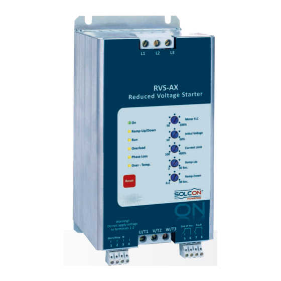
Page 15: Front Panel
(3) Reset Button Potentiometers settings Potentiometer Description Range Motor FLC 50-100% The adjustment allows easy setting of the RVS-AX current level, automatically adjusting current based functions (Overload, Current Limit, etc). Set FLC potentiometer according to the following equation: Motor × Where: Motor FLA is the motor's Full Load Current rating as shown on its nameplate. - Page 16 16 • Front Panel Potentiometer Range Description Initial Voltage 10-50% Determines the initial voltage to the motor (torque is directly proportional to the square of the voltage). Range: 10-50% of nominal voltage. This adjustment also determines the inrush current and mechanical shock.
-
Page 17: Indication Leds And Reset Button
17 • Front Panel Potentiometer Description Range Ramp Down 0.2-30 sec. Used to control deceleration of high friction loads. When Ramp-Down potentiometer is set, upon stop signal the starter output voltage is gradually ramped down. When "Ramp-down Time" is set to minimum, the motor will stop immediately. -
Page 18: Starting Procedure
18 • Starting Procedure STARTING PROCEDURE When mains voltage is connected to the RVS-AX, even if start signal has not been issued, full voltage may appear on the starter load terminals. Therefore, for isolation purposes, it is necessary to connect an isolating device before (upstream) the starter. -
Page 19: Standard Starting Procedure
19 • Starting Procedure Standard starting procedure 1. Set FLC (Motor Full Load Current) - according to calculation: Motor FLA × Starter F 2. Set other potentiometers according to system requirements (see next page for examples) 3. Connect mains voltage to starter line terminals. On LED will light. -
Page 20: Examples Of Starting Curves
20 • Starting Procedure Apply Start command If acceleration time is too short, increase Motor acceleration time “Acceleration Time” setting and/or decrease C.L. to full speed is as (when decreasing CL, make sure motor increases required? speed gradually and does not stall). End of process Examples of starting curves Light loads... -
Page 21: Trouble Shooting
21 • Trouble Shooting TROUBLE SHOOTING Upon fault – motor stops, Fault LED lights and Fault Relay operates. Fault Massage Cause and trouble shooting Overload LED Trips the starter when current exceeds the overload level and thermal lights. register has filled up. Check FLA, FLC and Overload settings, check motor current, wait at least 15 minutes to let motor and starter cool down before restarting. -
Page 22: Warranty Claim And Fault Inquiry
Country: Fax Number: Model Number And Build Example: 170 – 400 – 8 – S Options: RVS-AX _ _ _ - _ _ _ - __ - _ Serial Number: Purchasing Date: Sale / Installation Date: Failure Date: Draw one line diagram:... -
Page 23: Technical Specifications
575 - 600 Vac +10% -15% Frequency 50 / 60 Hz Load Three-Phase, Three-Wire, Squirrel Cage Induction Motor Degree of protection RVS-AX 8-44A: IP 20 RVS-AX 58-170A: IP 00 Altitude 1000 m above sea level Consult factory for derating Adjustments FLC (Full Load Current) - Page 24 8 gn Conforming to EN 60947-4-2 Vibration resistance 2 gn Conforming to EN 60947-4-2 Output relay End of Acceleration Contact N.O. 8 A, 250 V Fault Contact N.O. 8 A, 250 V Notes: Solcon Industries Ltd. www.solcon.com; Technical support: office@solcon.com ________________________________________________________________________________________________...
Need help?
Do you have a question about the RVS-AX and is the answer not in the manual?
Questions and answers