Table of Contents
Advertisement
Advertisement
Table of Contents

Summary of Contents for Apollo XPander
- Page 1 Commissioning guide...
-
Page 2: Table Of Contents
Contents Introduction Environmental Handling precautions Quick start guide for XPander Diversity Site Survey Quick start guide for XPander Diversity Loop Interface Installation Menu - scrolling and selecting Initial power up screen Multiple Interfaces Logging on interfaces Log on procedure Menu options Menu Level: (1.0) -
Page 3: Introduction
Apollo. The radio bases and signalling devices are addressable and use a pre-set analogue value to report via the Apollo protocol. Apart from normal and fire the bases can send pre-set analogue values to indicate low battery, detector contaminated, detector tamper and low signal strength fault conditions. -
Page 4: Environmental
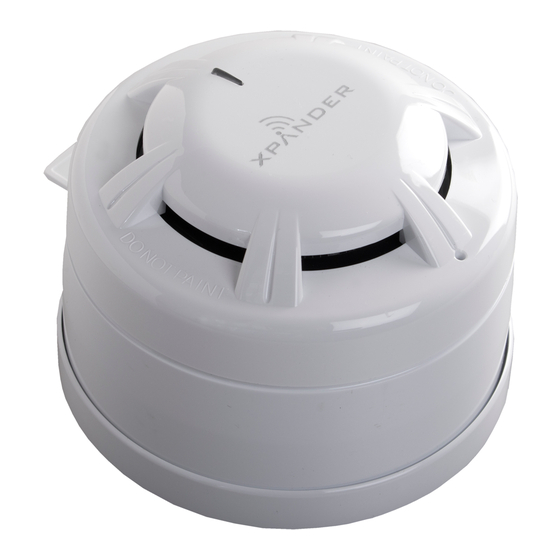
XPander detectors are supplied with a mounting base as a complete unit. The range comprises of the following products: Description Part Number Optical detector with base XPA-CB-12034-APO Heat detector A1R and base XPA-CB-11170-APO Heat detector CS and base XPA-CB-11171-APO Combined sounder and optical smoke detector... -
Page 5: Quick Start Guide For Xpander Diversity Site Survey
Quick Start Guide for XPander Diversity Site Survey For detailed instructions see page 16 1. Use the site survey tool to check the signal strength. 2. Record all the survey signal For site survey sheet see page 17 strengths on the site survey sheet. -
Page 6: Installation
The log on procedure (page 8) along with a completed site survey sheet should be sufficient to obtain a stable working system, the site survey procedure ensures all XPander devices will communicate correctly once installed. These sheets need to be completed and kept as commissioning and user documentation to comply with BS5839 - 1 section 2-27 and section 5-39 &... -
Page 7: Initial Power Up Screen
5-segment DIL switch on the base of the sounder or sounder visual indicator. Note: I/O Units and the Combined Sounder Visual Indicator Base do not have an XPert card, the addressing is set by a DIL switch. © Apollo Fire Detectors Limited 2015... -
Page 8: Logon Procedure
PRESS HERE TO LOGON A five-figure code will be displayed on the interface similar to below. This is the XPander device’s unique ID. A127D Turn the rotary select switch to ‘Yes’ and push to select. The menu will return to ‘add new device’. -
Page 9: Menu Options
Alarm Status switch. Battery Level Signal Level Manual Update Ident For a full range of analogue values please see Appendix A on page 14 © Apollo Fire Detectors Limited 2015... -
Page 10: Menu Level: (1.2)
Alkaline Varta Industrial 1.5V C (4014, LR14) for sounders only Note: When replacement batteries are required all batteries must be replaced together. * Batteries need to be changed as soon as possible (recommendation 7 days) © Apollo Fire Detectors Limited 2015... -
Page 11: Menu Level: (1.4)
Signal Level Manual Update Ident Menu Level: (1.7) Fault Status Alarm Status This menu indicates the detector type on a Combined Sounder Visual Battery Level Indicator Base. Signal Level Manual Update Ident Type © Apollo Fire Detectors Limited 2015... -
Page 12: Menu Level: (2.0)
From this menu new or additional devices can be logged on to the interface up to 31 devices. (Log on procedure on page 8). Add New Device Remove Device See page 7 for details of compatibility for XPander interfaces and devices. Interface Status Radio Channels Menu Level: (3.0) This menu shows a list of devices logged on to the interface. -
Page 13: Menu Level: (4.3)
Menu Level: (5.2) communications from other XPander devices. It will scan for other sources Currently Used of background noise. The auto selected channels should not be used when... - Page 14 Ch 23 Ch 12 Ch 29 If there is more than one XPander Interface on the site: have ALL the channels been set as above? Has the XPander Interface been installed as per the survey and installation instructions, allowing two metres from electrical...
- Page 15 Combined sounder-visual indicator (red) and detector base XPA-WB-14037-APO Combined sounder-visual indicator (white) and detector base XPA-WB-14038-APO Appendix E Site Survey Instructions PP2323 - see next page Appendix F Radio Site Survey Sheet - see page 17 © Apollo Fire Detectors Limited 2015...
- Page 16 It is therefore essential that a full site survey is carried out as part of the system design prior to any XPander devices being installed.
- Page 17 SHEET XPander Radio Site Survey Sheet (Copy this sheet for additional interfaces) SITE NAME DATE PANEL INTERFACE NUMBER LOCATION Signal Strength Location © Apollo Fire Detectors Limited 2015...
- Page 18 Status of building at the time of survey Notes This sheet needs to be completed and kept as commissioning and user documentation to comply with BS 5839 - 1 section 2-27 and section 5-39 & 40 Name Approved for installation Signature © Apollo Fire Detectors Limited 2015...
- Page 19 PP2286/2015/Issue 11...


Need help?
Do you have a question about the XPander and is the answer not in the manual?
Questions and answers