
Related Manuals for Asus UX363EA


Summary of Contents for Asus UX363EA
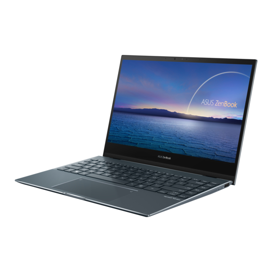
- Page 1 First Edition / September 2021 Customer Self Repair (CSR) Maintenance and Service Guide...
- Page 2 ASUS will only be responsible for or indemnify you for loss, damages or claims based in contract, tort or infringement under this Warranty Statement. This limit also applies to ASUS’ suppliers and its reseller. It is the maximum for which ASUS, its suppliers, and your reseller are collectively responsible.
-
Page 3: Table Of Contents
Table of Contents Disclaimer......................Safety precautions....................4 Installation tools....................5 Before disassembly....................5 Removing the base cover...............6 Installing an M.2 card (SSD)..................9 Customer Self Repair Guide... -
Page 4: Disclaimer
ASUS AND ITS AFFILIATES WILL NOT BE HELD LIABLE FOR ANY OF YOUR CONFIDENTIAL, PROPRIETARY OR PERSONAL DATA NOR ANY LOST OR CORRUPTED DATA, PROGRAMS OR SOFTWARE. -
Page 5: Installation Tools
Installation tools Screwdriver Non-conductive pry tool Tweezers Anti-static gloves Before disassembly Before your disassembly, we strongly recommend that you prepare a smartphone or other handheld camera. During disassembly, use your camera to take photos to help you remember the order of assembly and location of parts. When lifting the base cover off, slowly and carefully open so the angle is as small as possible. -
Page 6: Removing The Base Cover
Removing the base cover Disassembly Notice NOTE : The appearance of your Notebook PC’s bottom view may vary per model. Remove the screw(s) from the Notebook PC’s base cover. Assembly Notice Righty - Tighty Lefty - Loosey Customer Self Repair Guide... - Page 7 Use the non-conductive pry tool to lift open the indicated area of the base cover as shown in the illustration. Start Start Disassembly steps: IMPORTANT! Avoid sliding the non-conductive pry tool along the side of your Notebook PC to prevent damage. Customer Self Repair Guide...
- Page 8 Pull out the base cover and remove it completely from your Notebook PC. Customer Self Repair Guide...
-
Page 9: Installing An M.2 Card (Ssd)
Installing an M.2 card (SSD) Refer to the following steps when installing a compatible M.2 card (SSD) in your Notebook PC: IMPORTANT! Purchase your M.2 card from authorized retailers of this Notebook PC to ensure maximum compatibility and reliability. WARNING! Disconnect all the connected peripherals, any telephone or telecommunication lines and power connector (such as external power supply, battery pack, etc.) before removing the base cover. - Page 10 Disassembly Notice A. Before handling components, wear anti-static gloves to avoid damaging them due to static electricity. Remove the base cover. NOTE : For more details, refer to the removing the base cover section in this manual. Disconnect the cable from the battery connector. Disassembly steps: Use the non-conductive pry tool to push iron sheet.
- Page 11 Disassembly Notice Remove the M.2 card (SSD). NOTE : If there is material pasted on the M.2 card (SSD), when you replace M.2 card (SSD), please paste the material on the new M.2 card (SSD). (Not included specification label.) Disassembly steps: Remove the screw*1pc and M.2 card (SSD).
- Page 12 Assembly Notice Paste the ABSORBER to new M.2 card (SSD). Assembly the M.2 card (SSD). Assembly steps: Align and insert the new M.2 card into the module slot. Secure the M.2 card in place by fastening the screw. Please follow the below steps to attach the battery connector. Customer Self Repair Guide...
- Page 13 Assembly Notice Install the base cover at a slight tilt at upper side first, and then press the upper side of base cover to fix from right to left. 15~30 ͦ Put the base cover down slowly, and then press left and right side of base cover to fix, and press lower side of base cover to fix.
- Page 14 Customer Self Repair Guide...
Need help?
Do you have a question about the UX363EA and is the answer not in the manual?
Questions and answers