Table of Contents
Advertisement
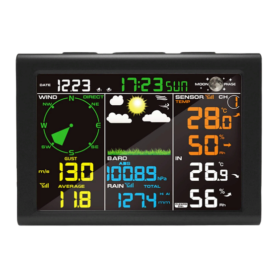
FT0835
Professional Wireless Weather Station
1.Introduction
Thank you for your purchase of the FT0835
following user guide provides step by step instructions for installation, operation and
troubleshooting.
2.Warnings
Warning: Any metal object may attract a lightning strike, including your weather
station mounting pole. Never install the weather station in a storm.
Warning: Installing your weather station in an elevated location may result in injury or
death. Safety goes first. Make sure your setup and preparation is secure, and take no risks.
3.Getting Started
The FT0835 weather station consists of a display console (receiver), a sensor array with
Integrated Outdoor Transmitter and mounting hardware
3.1.Parts List
The FT0835 weather station consists of the following parts (as referenced in Figure 1 ).
QTY
Display Console
Frame Dimensions (LxHxW):
1
135X26X96mm
LCD Dimensions (LxW): 111 x 75mm
Integrated Outdoor Transmitter
1
Dimensions (LxHxW):
330x150x280mm
Professional Wireless Weather
Item
1
User Manual
station. The
Image
Advertisement
Table of Contents

Subscribe to Our Youtube Channel
Related Manuals for Sainlogic FT0835


Summary of Contents for Sainlogic FT0835
- Page 1 The FT0835 weather station consists of a display console (receiver), a sensor array with Integrated Outdoor Transmitter and mounting hardware 3.1.Parts List The FT0835 weather station consists of the following parts (as referenced in Figure 1 ). Item Image Display Console...
- Page 2 Item Image Foot Mounting (with pole insert) Dimensions: 84x 152 x 216mm Mounting Bracket Back Plate (pole mount) Dimensions: 76 x 102 x 38mm Mounting Pole Dimensions: 76 x 76 x 25mm Pole mounting nuts (M3) / bolts Ø3) Pole mounting nuts (M5) / bolts ( Ø5) Tapping screws Manual...
-
Page 3: Recommend Tools
Item Image Power Adapter Figure 1 3.2 Recommend Tools ● Precision screwdriver (for small Phillips screws) ● Compass or GPS (for wind direction calibration) ● Adjustable Wrench ● Hammer and nail for Foot Mounting. 3.3 Sensor Assembly Set Up The following illustration shows the full segment for Thermo-Hygrometer ,WIND and RAIN transmitter .purposes only ,as shown in Figure 2. - Page 4 Figure 3 Remove the battery door on the back of the sensor by removing the set screw, as shown in Figure 4. Figure 4 Inserting 3xAA batteries in the battery compartment, as show in Figure 5.
- Page 5 Figure 5 Close the battery cover. Make sure the gasket (around the battery compartment) is properly seated in its place prior to closing the door. Tighten the set screw. Note: Do not install the batteries backwards. You can permanently damage the sensors. The solar panel does not charge the batteries, so rechargeable batteries are not needed or recommended.
- Page 6 Figure 6 3.4 Display Console 3.4.1 Display Console Layout The display console layout is shown in Figure 7 Note: The following illustration shows the full segment LCD display for description purposes only and will not appear like this during normal operation. Figure 7 1.Indoor humidity change indication 16.
- Page 7 It is recommended to plug in the power supply to reduce the battery consumption and extend the service life. Note: The sensor array must be powered and updating before powering up the console, or the console will time out searching for the sensors. Power the console last. Make certain the weather station sensor array is at least 3m away from the console and within 30m of the console.
- Page 8 Figure 9 1: Fold out the desk stand and see DC jack on the left ; as shown in Figure 10 Figure 10 2: Insert the DC plug correctly ; as shown in Figure 11 Figure 11 3: If you want to put it on a table or cabinet, opened the desk stand and turn the DC plug up until 90 degrees;...
- Page 9 Figure 12 4: If you want to hang on the wall, turn the DC plug down until 0 degrees and closed the desk stand; as shown in Figure 13 Figure 13 Note: If the power adapter is plugged in, BL ON will display in the time area for three seconds when powered up.
-
Page 10: Weather Station Installation
(about 3m apart). The sensors should be within 10% (the accuracy is ± 5%). Allow about 30 minutes for both sensors to stabilize. 4.Weather Station Installation Pre Installation Check. Before installing your weather station in the permanent location, we recommend operating the weather station for one week in a temporary location with easy access. - Page 11 Plastics 10-15% Wood 10-40% Brick 10-40% Concrete 40-80% Metal 90-100% 5.Final Installation of Sensor Integrated outdoor transmitter installation. Professional Wireless Weather Station can be used in both the Northern and Southern Hemispheres. Prior to installation, you will need to calibrate the wind direction. 5.1.
- Page 12 Southern Hemispheres 5.2. Southern Hemispheres (SOU). For Southern Hemisphere installations, ignore these(N, S, E, W) and face the solar panel to the North (and in a sunny position) when installing the Integrated outdoor transmitter. Step 1: Install the Integrated outdoor transmitter and face the solar panel North. Step 2: Console operation is set to Southern Hemispheres ( SOU in the time area) in Location division.
- Page 13 Figure 15 Tighten the mounting pole to your mounting pole(purchased separately) with the four¢5 Bolts and M5 Nuts assembly, or fix on the wall with four tapping screw, as shown in Figure16.
-
Page 14: Low Battery Icon
Figure 16 6.Low Battery Icon A low battery indicator icon is shown in the display window for Integrated outdoor transmitter. When the low battery icon appears (the battery voltage is lower than 3.6V), replace the batteries in the sensor with fresh batteries. Be sure to never mix old and new batteries, and never mix battery types such as alkaline and lithium together. -
Page 15: Set (Program) Mode
2.Rainfall. Press the CHANNEL/+ or MIN/MAX/- key to toggle between 1h, 24h, week, month and total. To clear the total rain, press the CHANNEL/+ or MIN/MAX/- button until total rain is displayed. The total rain will flash. Press and hold the SET button for three seconds until total rain reads 0.0. -
Page 16: Sensor Search Mode
13. Location division.(default: Northern Hemisphere) Press the SETkey again to change the location division. Press the [+] key or [-] key to toggle the sunlight units Northern Hemisphere (NOR)or Southern Hemisphere(SOU).(refer to 5.0 Final Installation of Integrated outdoor transmitter) 7.3 Sensor Search Mode If Outdoor sensor loses communication, dashes (--.-) will be displayed. -
Page 17: Alarm Mode
Note: If plugged into AC power, the backlight will remain on. It is not recommended leaving the backlight on for a long period of time when operating on batteries only, or the batteries will run down quickly. 8.Alarm Mode The FT0835 includes the following alarms: Time(Alarm1 and Alarm2) Wind Gust Wind Average... -
Page 18: Alarm And Command Key Beeper On/Off Mode
To adjust the alarm parameter, Touch the [+] or [-] key to increase or decrease the alarm settings, or Touch and hold the [+] or [-] key for three seconds to increase or decrease the alarm settings rapidly. Press the ALARM key to turn on (the alarm icon will appear ) and off the alarm. Press the SNOOZE key once at any time to return to the normal mode. -
Page 19: Weather Forecasting
The following section describes additional features and display icons. 9.1 Weather Forecasting Note: The weather forecast or pressure tendency is based on the rate of change of barometric pressure. In general, when the pressure increases, the weather improves (sunny to partly cloudy) and when the pressure decreases, the weather degrades (cloudy to rain). The weather forecast is an estimation or generalization of weather changes in the next 24 to 48 hours, and varies from location to location. -
Page 20: Moon Phase
Cloudy Pressure is falling and the previous condition is partly cloudy or Pressure is rising and the previous condition is rainy. Rainy Pressure is falling and the previous condition is cloudy. 9.3 Moon Phase The following moon phases are displayed based on the calendar date. Figure 52 9.4 Pressure Threshold Setting The pressure threshold (the negative or positive rate of change of pressure signifying a... -
Page 21: Feels Like Temperature
The lower the level pressure threshold setting, the higher sensitivity for weather forecast changes. Locations that experience frequent changes in air pressure require a higher setting compared to locations where the air pressure is typically stagnant. 9.5 Feels Like Temperature Feels like temperature is a combination of Heat Index and Wind Chill. -
Page 22: Measurement Specifications
Figure 18 When the temperature is between 4.4C (40° F) and 26.7C (80° F), the OUT temperature is displayed (Feels Like temperature is the same as OUT temperature). 10. Specifications 10.1 Wireless Specifications Line of sight wireless transmission (in open air): 100m. Frequency: 433 MHz Integrated Outdoor transmitter interval: 16 seconds 10.2 Measurement Specifications... -
Page 23: Maintenance
panel. The batteries provide backup power when there is limited solar energy Minimum 12 months for sensors (use lithium batteries in cold weather climates less than -20 ° C) 11. Maintenance 1.Clean the rain gauge and wind transmitter once every 3 months. Unscr ew the rain collector funnel by turning it 30°... - Page 24 Problem Solution Wireless remote not reporting in to If any of the sensor communication is lost, dashes (--.-) will console. be displayed on the screen. To reacquire the signal, press and hold the CHANNEL/+ button for 3 seconds, and the There are dashes (--.-) on the display remote search icon will be constantly displayed.
Need help?
Do you have a question about the FT0835 and is the answer not in the manual?
Questions and answers