Table of Contents
Advertisement
Advertisement
Table of Contents

Related Manuals for Tiffen Steadicam M-2


Summary of Contents for Tiffen Steadicam M-2
- Page 1 Steadicam System Manual ® ™ LIT-888000, RevA...
-
Page 3: Table Of Contents
The Tiffen Company 90 Oser Avenue Hauppauge, NY 11788 TIP: This table of contents is hyperlinked to navigate you through the respective pages. Visit us at Tiffen.com Jump back to this page by clicking on any page number throughout the manual. Easy. -
Page 4: Evolution Of The Steadicam M-Series
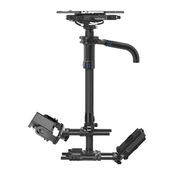
Evolution of the Steadicam M-Series he Steadicam M-2 is the most integrated and adaptable Steadicam system ever created. Not only does the M-2 offer a lighter weight and lower cost high-end system, it also features the revolutionary Steadicam Volt™ technology built right in for a sleeker, more versatile rig! The Volt electronics are seamlessly integrated into the low-profile top stage, and inside the all-new gimbal, to decrease the distance between the top of the gimbal and the top of the stage, as well as reduce weight. -
Page 5: Steadicam Modular Components Map
* 3-battery options are available TIP: Find a list of accessories, including the long gimbal handle and 3rd battery mounts, on page 52. Or visit Tiffen.com/steadicam for the very latest in modular components and accessories for M-1 and M-2 systems. -
Page 6: Stage Components
Stage components Dovetail Plate Clamp Lever Maximum rigidity and mounting options Safety latch design with drop-in loading Index marks for repeatability Adjustable tension M-1/Ultra compatible Front Electronics Power, Volt and tally ports Balance Drive Knobs Side-side and fore-aft adjustment Volt Switch Box Accessory Rod Mounts For optional VOLT electronics LWS 15mm by 60mm spacing... -
Page 7: Inputs And Outputs
NOTES: Tally sensitivity is set at maximum from the factory with active LO tally input signal, and this should work for most users. Contact Tiffen service for instructions on adjusting tally sensitivity and setting to active HI, if required. Also, there is a covered micro-USB port on the underside of the stage. This is ONLY for Volt firmware updates at the factory. -
Page 8: Camera Dovetail Clamp
Camera dovetail clamp he dovetail lock system is designed to ensure reliable camera safety. Mounting and removing the camera on the M-Series stages encourages you to keep at least one hand on the camera at all times, until it is securely fastened. With your camera mounted to the dovetail plate, follow these steps: The stage is ready for the camera Place the dovetail against the The weight of the camera will... - Page 9 Removing the camera is basically Open the clamp lever. Push and hold the safety latch to the reverse. Secure the camera The dovetail is still retained by the right. with your left hand. the safety latch. Keeping the safety latch held to Close the clamp lever so nothing the side, tilt the dovetail plate out catches on it! To reinstall the...
-
Page 10: Balance Drives
Balance drives ach knob has a twin on either side of the stage so you can adjust the balance from either side of the rig. With the coarse balancing done, and the camera locked in place, fine balancing can be finished with the adjustment knobs. -
Page 11: Tilt Stage
Tilt stage he tilt stage option enables you to easily tilt the camera relative to the post, which allows you to maintain dynamic balance while panning, and helps control headroom. It’s also very useful in low mode. The tilt stage of the M-2 offers 10˚ of upward or downward tilt. Unlock both tilt lock clamps. -
Page 12: Volt System Operation
The same adjustments are there. The same transparent assistance is there. Included below are some basics, but read the Volt manual to get the full picture: Tiffen.com/pages/volt-system. IMPORTANT: For optimal performance, balance your sled neutral (no drop time at all) when flying Volt. - Page 13 This can be done on the fly, even during a shot, a huge benefit to your operating. WARNING: Use the Tiffen Padded Dock to protect Volt electronics, as well as make docking and balancing easier. Other methods of docking may damage the unit!
- Page 14 he three dials on the dial box allow you to customize the behavior of the Volt in two axes, roll and tilt, independently. Additionally, the damping dial controls how the system returns the sled to vertical. Here are some general guides to the three knobs. The ROLL dial controls the Damping works like friction to The TILT dial controls the strength...
- Page 15 High roll/tilt resistance. FRICTION MODE Like a fluid head, TILT is drag. SO MANY TILTS Normal mode, when tilting more than 60˚ from vertical. NOTE: Read the Volt manual at Tiffen.com/pages/volt-system (LIT-817001) for everything else you need to know about the Volt.
-
Page 16: Adjustments And Maintenance
Adjustments and maintenance he dovetail clamp creates tremendous clamping force with very little pressure at the clamp lever. When the rig is new, get accustomed to the feel of each mechanism so that you can determine if one needs attention later. The ideal adjustment will not allow the dovetail to slide, even with the heaviest camera, but remains easy to close fully. - Page 17 f the fore/aft or side-to-side drive knobs exhibit free play, your balancing accuracy may be compromised. However, over-tightening can be worse than being a little loose, so approach these adjustments with care. Tighten the stage drive knobs in pairs; BOTH fore/aft or BOTH side/side knobs. Each pair of knobs share an axle and should be tensioned evenly.
-
Page 18: Installing Volt Electronics
Installing Volt electronics he Volt electronics are hidden inside the top stage, just beneath the dovetail clamp. All M-2 sleds are pre-wired to easily upgrade to Volt. Factory installation is recommended, but it’s not too difficult. CAUTION: Take proper ESD protection when installing the Volt control board into the stage, and confirm that no batteries are installed on the sled at time of installation. -
Page 19: Installing Or Moving Volt Control Boxes
Installing or moving Volt control boxes nside the stage nose are connectors for the Volt control boxes. Installation is straight forward, as shown. Or, you may wish to swap sides of the boxes, so the dials face an operator with regular or goofy stance. Remove the four screws, and Unscrew the two hex screws in Choose which side for each... -
Page 22: Post Components
Post components he new modular 1.58” posts for the M-2 system offer maximum rigidity whether they’re built short, or at full extension, and they’re compatible with the M-1 stage and base. This modularity allows users quick access to the stage, gimbal and base components for future upgrades, mods and maintenance. Stage Connector Electrical and mechanical junction to the stage Removable to allow access to gimbal... -
Page 23: Post Lock Adjustment
Post lock adjustment he low-profile post clamps are easy to use and offer a positive lock. You should occasionally test to ensure the gimbal and post are being clamped fully by trying to move the components with the clamps closed. If the components slide with a camera on board, it will affect your drop time. IMPORTANT: Do not over-tighten post clamps! They are strong enough to distort the carbon fiber post sections, but do not need to be that tight to hold. -
Page 24: Separating And Connecting Modular Parts
Separating and connecting modular parts he three major components —the stage, post and base— all connect through the post connectors. You can easily gain access to your gimbal by removing the stage. Here’s how it works: If you have a tilt stage, start with Use a 7/64”... - Page 25 einstalling the stage is easy, but remember to only use the provided high-strength screws. All twelve in the clamp and stage connector are the same size and spec. Spares are available. Align the stage connector’s red Align the center of the stage with Install the six screws with a 7/64”...
- Page 26 emoving or replacing the base is easier than the top stage, because there are fewer parts, and fewer of those high-strength screws. The base connector is the same as the stage connector. For years of trouble free use, don’t force anything, and keep them clean while separated. To remove the base, start by Use a 9/64”...
-
Page 28: Gimbal Components
Volt compatible Gimbal Grip Knurled for positive feel Arm Post Receiver With holes for Tiffen or PRO low-mode bracket pins Adapts from 3/4” to 5/8” arm posts with included insert Optional insert for 1/2” posts: 888-7139-01 Clamp Lever Over-center, tools free lock Shown here closed NOTE: The gimbal section of this user guide covers product numbers M2-GIM, and M2-GIMV. -
Page 29: Gimbal With Volt Components
Hirose 4-pin for the gimbal pan encoder Belt Tension Screw Adjusts handle belt WARNING: Docking methods other than the Tiffen padded dock may damage the unit! Use the padded dock to protect your Volt electronics, as well as make docking and balancing easier. -
Page 30: Volt Compared To M-1 Volt
M-2 Volt compared to M-1 Volt olt integration into the new M-2 gimbal differs from an installation on an M-1 gimbal in two practical ways: the pan encoder is now internal, and the trunnion pulley has a different mechanism (similar to previous “upgrade kits”... -
Page 31: Gimbal Clamp Adjustment
Gimbal clamp adjustment he low-profile gimbal clamp is easy to use and offers a positive lock. You should occasionally test to ensure the post is being clamped fully by trying to move the gimbal with the clamps closed. If the gimbal slides with a camera on board, it will affect your drop time. -
Page 32: Pan Bearing Removal And Cleaning
Pan bearing removal and cleaning he modular nature of the M-2 encourages operators to take excellent care of their rigs. Cleaning the pan bearing from time to time will keep your M-2 performing at its best. Start by removing the gimbal from the post (see page 24), then grab the included Blue Whale tool (305-7115-02). - Page 33 DO NOT use compressed air to blow off excess acetone or dry bearings. • Add 5 to 10 drops of Tiffen bearing oil (888- 7116) on the bearing balls and slowly turn the bearing to distribute the oil.
-
Page 34: Pan Bearing Replacement
Whale spanner to tighten. And fully seated. you’re done! TIP: A small amount of Tiffen bearing oil (888-7116) may be applied to the inside or outside of the bearing to aid reassembly, if necessary. DO NOT use grease anywhere! -
Page 36: Monitor Mount Components
Monitor mount components Universal Monitor Mount Adjustable width and height Monitor Pivot 180˚ range for unobstructed views Adjustable friction Pivot Clamp Knob Monitor Rods Secure tilt angle of mount LWS 15mm by 60mm spacing Standard 1/2”-13 threaded ends Rod Clamp Levers Post Clamp Lock or release the monitor rods Hinged quick-release... -
Page 37: Monitor Mount Positioning
Monitor mount positioning he M-2 monitor mount is intended to allow practically limitless mounting positions. The monitor can be positioned close to the post or far away. The mount can attach to either post. The monitor can be tilted to any angle and arched from upright to inverted. Many of the possibilities take mere seconds to achieve and none take more than a minute. -
Page 38: Clamp Operation
Clamp operation ou can easily move the monitor mount from the lower post to the gimbal post. While the mount is off the post, you may also flip it over so the monitor will be upright in low-mode. IMPORTANT: support the monitor with one hand while disengaging and engaging the clamp. Open the clamp lever, and then Pull the monitor away from the Reposition the monitor mount... -
Page 39: Monitor Yoke Adjustment
NOTE: Contact Tiffen for a selection of monitor blocks to fit your choice of professional monitor when upgrading or buying a spare. -
Page 40: Adjusting Monitor Clamps And Hinge Brakes
Adjusting monitor clamps and hinge brakes hough the levers only have a short 45˚ throw, the rod clamps hold the monitor rods securely when properly adjusted. If they slide with a camera on board it will affect your static balance. Adjust the clamp locks with the Turn each locknut a small amount Test the holding power of the... -
Page 42: Base And Battery Mount Components
Base and battery mount components Front Battery (#2) With 12V P-Tap V-lock or Gold Mount Battery Pivot Adjustable friction 180˚ range Clamp Levers 3rd Battery Switch Lock or release the battery rods Choose 12V or 24V when running 3rd battery Front Electronics High-definition video ports Power ports... -
Page 43: Base Electronics
Base electronics Front Electronics Triple HD video ports Monitor Port Double 12/24V ports HD-SDI compatible LEMO® 5-pin 1B connector LEMO® 3-pin 0B connector Direct connections to the stage Power and tally signal 12 volts supplied at all times Color coded at each end No SD video signal 12 and 24 volts simultaneously when in 24V mode... -
Page 44: Battery Positioning
Battery positioning he battery mount can be brought in tight to the base for a whippy feel and plenty of leg clearance for switches. Or, the battery mount can be elongated to increase pan inertia and to balance a monitor placed way out front. -
Page 45: Installing The 3 Rd Battery Mount
Installing the 3 battery mount he optional 3rd battery mount has integrated wiring, so it doesn’t use one of your power ports. Once you install the included short dovetail, the 3rd battery mount can slide on and off as needed. Remove the screws holding on the Reposition the pre-wired multi-pin Install the dovetail with the screws. -
Page 46: Three Batteries, Three Switches
Three batteries, three switches ou’re in full control of how batteries are combined on the M-2. The main ON-OFF switch turns power ON or OFF, except for P-taps on each battery mount. The main 12V/24V switch adds the #2 battery in series or parallel with battery #1. -
Page 48: Connector Diagrams And Warnings
Connector diagrams and warnings Pin2 Pin1 Pin12 Pin12 Pin1 Pin2 Warnings: • When mounting “sandwiched” accessories to a battery mount with a battery on its back, in 24Volt mode, do so ONLY on the REAR #1 battery mount. Mounting it to the front #2 battery mount (closest to the post when upright) will damage the equipment in 24V mode. -
Page 49: And M-2 Features And Specs
M-1 and M-2 features and specs... -
Page 50: And M-2 Part Numbers
M-1 and M-2 part numbers... -
Page 52: And M-2 Accessories List
M-1 and M-2 accessories list... -
Page 54: Contact Tiffen
There is no implied or expressed warranty regarding this material. STEADICAM , Steadicam M-1™, Steadicam M-2™, and Steadicam Volt™ are trademarks of the Tiffen Company, LLC. All other ® trademarks and product names appearing herein are the property of their respective owners.
Need help?
Do you have a question about the Steadicam M-2 and is the answer not in the manual?
Questions and answers