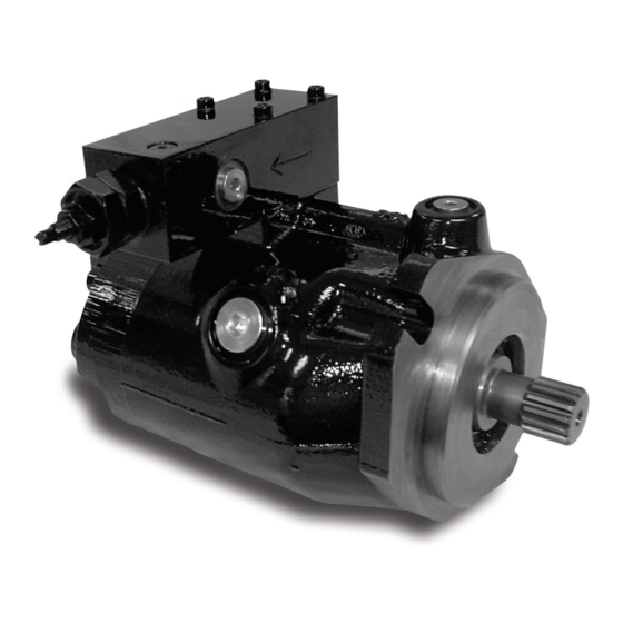
Parker P1 Series Bulletin
18cc to 140cc medium pressure axial piston pumps
Hide thumbs
Also See for P1 Series:
- User manual (242 pages) ,
- Service information (40 pages) ,
- Service information (60 pages)

Related Manuals for Parker P1 Series


Summary of Contents for Parker P1 Series
- Page 1 P1/PD Series: 18cc to 140cc Medium Pressure Axial Piston Pumps Variable Displacement – Service Information Bulletin HY28 - 2665 - 02/SVC/EN Effective: February 19, 2015...
- Page 2 Parker or its subsidiaries or authorized distributors. To the extent that Parker or its subsidiaries or authorized distributors provide component or system options based upon data or specifications provided by the user, the user is responsible for determining that such data and specifications are suitable and sufficient for all applications and reasonably foreseeable uses of the components or systems.
-
Page 3: Table Of Contents
060, 075, 100, 140 assembly…...…………………………………………………………........... 50 060, 075, 100, 140 assembly tools..……………………………………………………….......... 54 060, 075, 100, 140 test procedure…………………………………………………………......... 56 Conversions and formulas………...…………………………………………………………........59 Offer of sale………………………..…………………………………………………………........63 Parker Hannifin Corporation Hydraulic Pump and Power Systems Division Marysville, Ohio USA... -
Page 4: General Information
The fluid recommended for use in these pumps has a petroleum base and contains agents which provide oxidation inhibition and anti-rust, anti-foam and de-aerating properties as described in PARKER standard HF-1. Where anti-wear additive fluids are specified, see PARKER standard HF-0. -
Page 5: Start Up Procedure
8.2% per turn (3.7 cc/turn) 0-50% 4.6% per turn (2.76 cc/turn) 0-45% 4.3% per turn (3.23 cc/turn) 0-45% 3.9% per turn (3.9 cc/turn) 0-25% 3.3% per turn (4.62 cc/turn) Parker Hannifin Corporation Hydraulic Pump and Power Systems Division Marysville, Ohio USA... -
Page 6: Troubleshooting
(line volume, line stretch, acumulator eliminate hose effects) Parker Hannifin Corporation Hydraulic Pump and Power Systems Division Marysville, Ohio USA... - Page 7 Parker Hannifin Corporation Hydraulic Pump and Power Systems Division Marysville, Ohio USA...
-
Page 8: 18Cc, Model Ordering Code
Electronic valve with zero displacement default and hydromechanical Pmax (CANBUS compatible) Electronic valve with max displacement default and hydromechanical Pmax (CANBUS compatible) *** W, X, Y and Z only available with *D* and *Y* Parker Hannifin Corporation Hydraulic Pump and Power Systems Division... -
Page 9: 28Cc, Model Ordering Code
Electronic valve with zero displacement default and hydromechanical Pmax (CANBUS compatible) Electronic valve with max displacement default and hydromechanical Pmax (CANBUS compatible) *** W, X, Y and Z only available with *D* and *Y* Parker Hannifin Corporation Hydraulic Pump and Power Systems Division... -
Page 10: 45Cc, Model Ordering Code
Electronic valve with zero displacement default and hydromechanical Pmax (CANBUS compatible) Electronic valve with max displacement default and hydromechanical Pmax (CANBUS compatible) *** W, X, Y and Z only available with *D* and *Y* Parker Hannifin Corporation Hydraulic Pump and Power Systems Division... -
Page 11: 60Cc, Model Ordering Code
Electronic valve with zero displacement default and hydromechanical Pmax (CANBUS compatible) Electronic valve with max displacement default and hydromechanical Pmax (CANBUS compatible) *** W, X, Y and Z only available with *D* and *Y* Parker Hannifin Corporation Hydraulic Pump and Power Systems Division... -
Page 12: 75Cc, Model Ordering Code
Electronic valve with zero displacement default and hydromechanical Pmax (CANBUS compatible) Electronic valve with max displacement default and hydromechanical Pmax (CANBUS compatible) *** W, X, Y and Z only available with *D* and *Y* Parker Hannifin Corporation Hydraulic Pump and Power Systems Division... -
Page 13: 100Cc, Model Ordering Code
Electronic valve with zero displacement default and hydromechanical Pmax (CANBUS compatible) Electronic valve with max displacement default and hydromechanical Pmax (CANBUS compatible) *** W, X, Y and Z only available with *D* and *Y* Parker Hannifin Corporation Hydraulic Pump and Power Systems Division... -
Page 14: 140Cc, Model Ordering Code
Electronic valve with zero displacement default and hydromechanical Pmax (CANBUS compatible) Electronic valve with max displacement default and hydromechanical Pmax (CANBUS compatible) *** W, X, Y and Z only available with *D* and *Y* Parker Hannifin Corporation Hydraulic Pump and Power Systems Division... -
Page 15: Technical Data
131 125 115 123 130 bar range (C1) = 18.6 Bar/Turn • Pressure compensator (AM) 10 to * Based on NFPA testing standards 40 bar range = 20 Bar/Turn Parker Hannifin Corporation Hydraulic Pump and Power Systems Division Marysville, Ohio USA... -
Page 16: 018 & 028 Pump Exploded View
Medium Pressure Axial Piston Pumps Bulletin HY28-2665-02/SVC/EN 18cc & 28cc Pump Exploded View P1/PD Maintenance Parker Hannifin Corporation Hydraulic Pump and Power Systems Division Marysville, Ohio USA... -
Page 17: 045 Pump Exploded View
Medium Pressure Axial Piston Pumps Bulletin HY28-2665-02/SVC/EN 45cc Pump Exploded View P1/PD Maintenance Parker Hannifin Corporation Hydraulic Pump and Power Systems Division Marysville, Ohio USA... -
Page 18: Parts List For 018, 028, 045
03E-94359-0 03E-94359-0 Bearing retainer Orifice 03E-94432-0 03E-94395-0 03E-94358-0 Cam bearing Housing (not sold seperatley) 108X6 108X8 488-35055-0 Plug, SAE ORB Consult Parker Rep. Plug, BSPP Consult Parker Rep. Plug, ISO 695-00908-0 695-00908-0 695-00910-0 SAE O-ring 787140 P2-060-3304 620-82125-5 Shaft Seal... - Page 19 Medium Pressure Axial Piston Pumps Bulletin HY28-2665-02/SVC/EN Notes P1/PD Maintenance Parker Hannifin Corporation Hydraulic Pump and Power Systems Division Marysville, Ohio USA...
-
Page 20: 060, 075, 100 & 140 Pump Exploded View
Medium Pressure Axial Piston Pumps Bulletin HY28-2665-02/SVC/EN Pump Exploded View 060, 075, 100, 140 P1/PD Maintenance 34 35 36 37 Parker Hannifin Corporation Hydraulic Pump and Power Systems Division Marysville, Ohio USA... -
Page 21: Parts List For 060, 075, 100, 140
BSPP O-ring 620-82118-5 620-82118-5 620-82121-5 620-82120-5 Shaft Seal 356-65146-0 356-65146-0 356-65147-0 356-65148-0 Seal Retainer See separate compensator ordering information. Compensator * Denotes item is included in the seal kit Parker Hannifin Corporation Hydraulic Pump and Power Systems Division Marysville, Ohio USA... -
Page 22: Electronic Control Exploded View
Medium Pressure Axial Piston Pumps Bulletin HY28-2665-02/SVC/EN Electronic Control Exploded View P1/PD Maintenance Torque to 5 ft-lbs (6.8 Nm) Parker Hannifin Corporation Hydraulic Pump and Power Systems Division Marysville, Ohio USA... -
Page 23: Parts List For Electronic Control
Secure with screws & washers, 2 places. & washers, 2 places. & washers, 2 places. & washers, 2 places. Final Position Final Position Final Position Final Position Parker Hannifin Corporation Hydraulic Pump and Power Systems Division Marysville, Ohio USA... -
Page 24: Case To Inlet Check Valves
Item No 018, 028, 045 060, 075, 100, 140 Description 314-10000-0 Hollow Set Screw 314-10002-0 03E-93931-0 Check Valve Poppet 03E-94720-0 03E-93987-0 Spring 03E-94721-0 03E-93988-0 Check Valve Stop 03E-94722-0 Parker Hannifin Corporation Hydraulic Pump and Power Systems Division Marysville, Ohio USA... -
Page 25: Volume Stop
S2E-19204-5 S2E-19114-5 S2E-18987-5K S2E-18988-5K Maximum Volume Stop Kit S2E-19208-5 S2E-19114-5 Use Above Minimum Volume Adjustment Kit ** Contact HPD technical support Maximum and minimum volume stops use the same components except where noted. Parker Hannifin Corporation Hydraulic Pump and Power Systems Division Marysville, Ohio USA... -
Page 26: Seal And Parts Kits
03E-94270-0 03E-93943-0 695-00251-0 SAE D&E, 13 Tooth 03E-93942-0 695-00259-0 Seal Kits S2E-18709-5K S2E-19118-5K S2E-19066-5K S2E-18697-5K S2E-18004-5K S2E-18460-5K S2E-18158-5K Note: Seal kits contain all the seals required for any pump configuration. Parker Hannifin Corporation Hydraulic Pump and Power Systems Division Marysville, Ohio USA... - Page 27 Note: AM control can be converted to an AL control with conversion kit S2E-19117-0. European customers will receive a solid spool in this kit. US customer will receive a set screw to plug orifice in spool. Parker Hannifin Corporation Hydraulic Pump and...
-
Page 28: "L" Compensator
Main Compenator Outer Spring L0 & L2 versions only Main Compensator Inner Spring Main Compensator Spring Seat & Piston Compensator Seal Piston O-ring Table CONTINUED on next page. Parker Hannifin Corporation Hydraulic Pump and Power Systems Division Marysville, Ohio USA... - Page 29 Hardened SAE #2 O-ring boss plug 4.0 ± 0.6 N-m (35 ± 5 in-lbs) Teflon O-ring Roll pin Hex mounting screw 5.0 ± 0.3 N-m (45 ± 3 in-lbs) Parker Hannifin Corporation Hydraulic Pump and Power Systems Division Marysville, Ohio USA...
-
Page 30: "C" Compensator
5.0 ± 0.3 N-m (45 ± 3 in-lbs) SAE #2 O-ring Hardened SAE #2 O-ring boss plug 4.0 ± 0.6 N-m (35 ± 5 in-lbs) Teflon O-ring Roll pin Teflon O-ring Parker Hannifin Corporation Hydraulic Pump and Power Systems Division Marysville, Ohio USA... -
Page 31: Ae, Af, Al, Am,An Compensator
P*075 SHOWN 48.6 AE* or AF* CONTROL "V" VENT PORT "V" VENT PORT P****PA P****PB P****PM P****PS PRESSURE COMPENSATOR PRESSURE ADJUSTING SCREW 4VP01 ADJU R70.2 R59.0 Parker Hannifin Corporation Hydraulic Pump and Power Systems Division 114.1 95.1 Marysville, Ohio USA... -
Page 32: Compensator Disassembly/Inspection
Free height: 25.9±0.5mm (1.020±0.020 in.) C0/L0/L2 Main compensator spring - outer Free height: 39±0.7mm (1.535±0.028 in.) Load Sense spring Free height: 14±0.4mm (0.551±0.016 in.) Bias spring Reference item numbers on page 26. Parker Hannifin Corporation Hydraulic Pump and Power Systems Division Marysville, Ohio USA... -
Page 33: Compensator Assembly
Load Sense Spool Load Sense Spool Load Sense Load Sense Main Compensator Main Compensator Spring Spring Inner Spring Inner Spring Main Compensator Spool Main Compensator Spool Main Compensator Spool Parker Hannifin Corporation Hydraulic Pump and Power Systems Division Marysville, Ohio USA... -
Page 34: 018, 028, 045 Disassembly
For complete overhaul, all o-rings and seals should be discarded and replaced. Identify the pump from information on the data tag. Figure 1 Identify the pump from information on the data tag. Figure 1 Figure 1 Parker Hannifin Corporation Hydraulic Pump and Power Systems Division Marysville, Ohio USA... - Page 35 Remove cam from housing. See Figure 2 control side of the pump housing (same side as the three seals on the housing flange). Figure 2 Large Pocket Pressure control side of pump Figure 2 Parker Hannifin Corporation Hydraulic Pump and Power Systems Division Marysville, Ohio USA...
- Page 36 Remove all SAE o-ring boss access plugs. Proceed to inspection section of this manual. Parker Hannifin Corporation Hydraulic Pump and Power Systems Division Marysville, Ohio USA...
-
Page 37: 018, 028, 045 Inspection
Inspect the spool bores for damage. Apply a light oil film on the appropriate spool and check its fit in the bore. The spool should fit snugly in housing and not have any radial play. Parker Hannifin Corporation Hydraulic Pump and Power Systems Division... -
Page 38: 018, 028, 045 Rework Limits
03E-93159-0 Compensator Free Height : +/- 0.5mm Page 28 & 30 26 mm Spring- Inner Load Sense 03E-93825-0 Free Height : +/- 0.4mm Page 28 Spring 14 mm Parker Hannifin Corporation Hydraulic Pump and Power Systems Division Marysville, Ohio USA... -
Page 39: 018, 028, 045 Assembly
Install the spherical guide ball into the hold down plate. While minimum maximum thickness 018 part # 028 part # 045 part # holding the guide ball against the hold down plate, install the pistons into the barrel. Parker Hannifin Corporation Hydraulic Pump and Power Systems Division Marysville, Ohio USA... - Page 40 10. Install the large o-ring in the groove on the port block. Install the three tef- lon o-rings on the pressure communication ports of the port block. CW compensator Parker Hannifin Corporation Hydraulic Pump and Power Systems Division Marysville, Ohio USA...
- Page 41 CW port plates to 5 ± 0.25 Nm (45 ± 3 in-lb). (See Figure 7) Dowel CW compensator Figure 7 CCW pump with CW pump with compensator compensator Parker Hannifin Corporation Hydraulic Pump and Power Systems Division Marysville, Ohio USA...
-
Page 42: 018, 028, 045 Assembly Tools
018/028/045 76.20 mm 50.80 mm 19.05 mm 28.82 mm 22.50 mm 15° “08” Shaft 3.00 in. 2.00 in. 0.75 in. 1.135 in. 0.885 in. (045 SAE) (045 ISO) Parker Hannifin Corporation Hydraulic Pump and Power Systems Division Marysville, Ohio USA... - Page 43 Pump Size 3.71 mm 19.9 mm 12.7 0.146 in. 0.772 in. ( 0.5) 4.00 mm 21.6 mm 0.157 in. 0.85 in. 4.00 mm 24.1 mm 0.157 in. 0.95 in. Parker Hannifin Corporation Hydraulic Pump and Power Systems Division Marysville, Ohio USA...
-
Page 44: 018, 028, 045 Test Procedure
018, 028, 045 Pump Test Procedure P1/PD Maintenance PUMP TEST PROCEDURE Test criteria based on hydraulic oil ISO 32 per Parker HF-0 specifications. Oil temperature: 50°C ± 2°C (120°F ±10°F). NOTE: insure that the hydraulic system does not overheat during this test procedure. - Page 45 Reduce output pressure to 273 ± 2 bar see performance chart (3960 ± 30 psi). Record output flow Verify no external leaks No leakage permitted Parker Hannifin Corporation Hydraulic Pump and Power Systems Division Marysville, Ohio USA...
-
Page 46: 060, 075, 100, 140 Disassembly
Additional fluid may drain out of the passages when the compensator is removed. Set compensator aside for later disassembly and inspection Remove the bolts attaching the port block to the main housing. Figure 1 Pump Data Tag Parker Hannifin Corporation Hydraulic Pump and Power Systems Division Marysville, Ohio USA... - Page 47 Place the port block wih piston guides in oven at 163° C (325° F) NOTE: To prevent annealing of heat treated surfaces: DO NOT USE A TORCH TO HEAT PISTON GUIDES. Large Pocket Pressure control side of pump Parker Hannifin Corporation Hydraulic Pump and Power Systems Division Marysville, Ohio USA...
-
Page 48: 060, 075, 100, 140 Inspection
Keyed shafts should be inspected for signs of brinelling and damage to the key area. Splined shafts may have a contact wear pattern but should not show excessive wear on the spline area. Parker Hannifin Corporation Hydraulic Pump and Power Systems Division... -
Page 49: 060, 075, 100, 140 Rework Limits
5.91 mm 6.41 mm 6.41 mm Total material allowed to (0.233 in.) (0.233 in.) (0.252 in.) (0.252 in.) be removed from shoe face when lapping is 0.076mm (0.003 in) Parker Hannifin Corporation Hydraulic Pump and Power Systems Division Marysville, Ohio USA... -
Page 50: 060, 075, 100, 140 Assembly
13. With the average, use chart 2 to determine the correct shim to install in the pump. 14. Rebuild the pump with the shaft bearings, and selected shim. Check end play, then disassemble port block and continue with pump assembly. Parker Hannifin Corporation Hydraulic Pump and Power Systems Division Marysville, Ohio USA... - Page 51 4.18 mm (.164 in) 4.08 mm (.1606 in) 03E-93575-0 03E-94158-0 03E-93979-0 4.19 mm (.165 in) 4.25 mm (.167 in) 4.16 mm (.1638 in) 03E-93576-0 03E-93864-0 03E-93980-0 Shim Kits: S2E-18591-0K S2E-18640-0K S2E-18527-0K Parker Hannifin Corporation Hydraulic Pump and Power Systems Division Marysville, Ohio USA...
- Page 52 (figure 4A). For left hand rotation the bias guide is installed nearest to the dowel pin (figure 4B). Torque the control and bias guides as specified in Chart 3 Parker Hannifin Corporation Hydraulic Pump and Power Systems Division...
- Page 53 29. Install o-ring seals and assembled compensator on side of pump housing. Pump rotation is indicated by arrow on compensator housing. Torque bolts to 5 ± 0.25 Nm (45 ± 3 in-lb). Parker Hannifin Corporation Hydraulic Pump and Power Systems Division...
-
Page 54: 060, 075, 100, 140 Assembly Tools
(2.088 in) (1.751 in) 114 mm 76.2 mm 22.4 mm 53.04 mm 50.04 mm 140 ISO 213-0-004201 15° (4.50 in) (3.00 in) (0.88 in) (2.088 in) (1.970 in) Parker Hannifin Corporation Hydraulic Pump and Power Systems Division Marysville, Ohio USA... - Page 55 060 & 075 213-0-004193 12° (2.120 in) (1.918 in) 65.1 mm 59.3 mm 213-0-004205 15° (2.562 in) (2.335 in) 71.1 mm 65.1 mm 213-0-004198 15° (2.80 in) (2.562 in) Parker Hannifin Corporation Hydraulic Pump and Power Systems Division Marysville, Ohio USA...
- Page 56 060, 075, 100, 140 Pump Test Procedure P1/PD Maintenance PUMP TEST PROCEDURE Test criteria based on hydraulic oil ISO 32 per Parker HF-0 specifications. Oil temperature: 50°C ± 2°C (120°F ±10°F). NOTE: insure that the hydraulic system does not overheat during this test procedure.
-
Page 57: 060, 075, 100, 140 Test Procedure
Reduce output pressure to 273 ± 2 bar see performance chart (3960 ± 30 psi). Record output flow Verify no external leaks No leakage permitted Parker Hannifin Corporation Hydraulic Pump and Power Systems Division Marysville, Ohio USA... - Page 58 See performance chart specified limits. Lock the load sense adjustment screw. Confirm differential pressure at 20 ± 2 bar (290 ± 30 psi). Verify no external leaks No leakage permitted Parker Hannifin Corporation Hydraulic Pump and Power Systems Division Marysville, Ohio USA...
-
Page 59: Conversions And Formulas
(cm /rev) Fluid motor torque pressure(bar) x displacement (cm /rev) x mech. eff. 20� Fluid motor power rpm x (cm /rev) x (bar) x overall eff. 600000 Parker Hannifin Corporation Hydraulic Pump and Power Systems Division Marysville, Ohio USA... - Page 60 Medium Pressure Axial Piston Pumps Bulletin HY28-2665-02/SVC/EN Notes P1/PD Maintenance Parker Hannifin Corporation Hydraulic Pump and Power Systems Division Marysville, Ohio USA...
- Page 61 Port plates for P1/PD 100 unit have been updated Volume stop kit numbers have been updated. New table layout. Load sense controller part numbers updated. Pressure compensator part numbers updated. Parker Hannifin Corporation Hydraulic Pump and Power Systems Division Marysville, Ohio USA...
- Page 62 Medium Pressure Axial Piston Pumps Bulletin HY28-2665-02/SVC/EN Notes P1/PD Maintenance Parker Hannifin Corporation Hydraulic Pump and Power Systems Division Marysville, Ohio USA...
-
Page 63: Offer Of Sale
P1/PD Maintenance The items described in this document and other documents and descriptions provided by Parker Hannifin Corporation, Hydraulics Group, and its authorized distributors (“Seller”) are hereby offered for sale at prices to be established by Seller. This offer and its acceptance by any customer (“Buyer”) shall be governed by all of the following Terms and Conditions. - Page 64 © 2015 Parker Hannifin Corporation, all rights reserved Bulletin HY28-2665-02/SVC/EN Effective: 02/2015 Parker Hannifin Corporation Hydraulic Pump and Power Systems Division 14249 Industrial Parkway Marysville, OH 43040 USA phone 937 644 4435 fax 937 642 3639 www.parker.com/hps...
Need help?
Do you have a question about the P1 Series and is the answer not in the manual?
Questions and answers