Table of Contents
Advertisement
Advertisement
Table of Contents
Troubleshooting

Related Manuals for Alpha ESS SMILE-S6-HV


Summary of Contents for Alpha ESS SMILE-S6-HV
- Page 1 Installation Manual Energy Storage System (ESS) SMILE-S6-HV SMILE-S5-HV...
-
Page 2: Imprint
Web: www.alpha-ess.com Add: JiuHua Road 888, High-Tech Industrial Development Zone 226300 Nantong City, Jiangsu Province Australia Alpha ESS Australia Pty. Ltd. Tel.: +61 1300 968 933 E-mail: australia@alpha-ess.com Web: www.alpha-ess.com.au Add: Suite 1, Level 1, 530 Botany Road, Alexandria, NSW, 2015 Italy Alpha ESS Italy S.r.l. -
Page 3: Copyright Statement
Your Smart Energy Copyright Statement This manual is under the copyright of Alpha ESS Co., Ltd. with all rights reserved. Please keep the manual properly and operate in strict accordance with all safety and operating instructions in this manual. Please do not operate the product before reading through the manual. -
Page 4: Table Of Contents
6. Mounting ....................... 23 6.1 Requirements for Mounting ................23 6.2 Preparing Tools and Instruments ..............26 6.3 Mounting the 8.2PH and Inverter ..............27 6.4 Mounting the 5PH and Inverter ..........错误!未定义书签。 ___________________________________________________________________ Alpha ESS Co., Ltd. Page 4 of 75... - Page 5 11.2 Packing the Product ................... 69 11.3 Disposing of the Product ................... 69 12. Specification ......................70 12.1 Datasheet of Hybrid Inverter SMILE-S6-HV-INV ..........70 12.2 Datasheet of Battery Pack SMILE-BAT-8.2PH ..........72 12.3 Datasheet of Battery Pack SMILE-BAT-5PH ......错误!未定义书签。...
-
Page 6: Information On This Document
Your Smart Energy 1. Information on this Document Content and Structure of this Document This document is valid for product of SMILE-S6-HV or SMILE-S5-HV which include inverter SMILE-S6-HV-INV or SMILE-S5-HV-INV&, battery pack SMILE-BAT-8.2PH. (SMILE-S6-HV/SMILE-S6-HV-INV is 6kW and SMILE-S5-HV/SMILE-S5-HV-INV is 5kW. This manual will use SMILE-S6-HV/SMILE-S5-HV-INV to represent two models.) -
Page 7: Nomenclature
Nomenclature Complete designation Designation in this document SMILE-BAT-8.2PH (INDOOR) SMILE-BAT-8.2PH (INDOOR) SMILE-BAT-8.2PH (OUTDOOR) SMILE-BAT-8.2PH (OUTDOOR) SMILE-S6-HV-INV (INDOOR) Inverter (INDOOR) SMILE-S6-HV-INV (OUTDOOR) Inverter (OUTDOOR) SMILE-S6-HV-INV with SMILE-BAT- Product 8.2PH ___________________________________________________________________ Alpha ESS Co., Ltd. Page 7 of 75... -
Page 8: Safety
The enclosed documentation is an integral part of this product. Keep the documentation in a convenient place for future reference and observe all instructions contained therein. The type label must remain permanently attached to the product. ___________________________________________________________________ Alpha ESS Co., Ltd. Page 8 of 75... -
Page 9: Safety Precaution For Battery Pack
1. If fire occurs when charging batteries, if it is safe to do so, disconnect the battery pack circuit breaker to shut off the power to charge. 2. If the battery pack is not on fire yet, extinguish the fire before the battery pack catches fire. ___________________________________________________________________ Alpha ESS Co., Ltd. Page 9 of 75... - Page 10 In water: Stay out of the water and don't touch anything if any part of the battery, inverter, or wiring is submerged. Do not use submerged battery again and contact the service engineer. ___________________________________________________________________ Alpha ESS Co., Ltd. Page 10 of 75...
-
Page 11: Important Safety Instructions
• Connect and ground the frame of the PV modules, the array frame and the electrically conductive surfaces so that there is continuous conduction. Observe the applicable local regulations. ___________________________________________________________________ Alpha ESS Co., Ltd. Page 11 of 75... - Page 12 • If moisture has penetrated the battery pack (e.g. due to a damaged enclosure), do not install or operate the battery pack. • In case of contact with electrolyte, rinse the affected areas immediately with water and consult a doctor without delay. ___________________________________________________________________ Alpha ESS Co., Ltd. Page 12 of 75...
- Page 13 Damage due to cleaning agents The use of cleaning agents may cause damage to the product and its components. • Clean the product and all its components only with a cloth moistened with clear water. ___________________________________________________________________ Alpha ESS Co., Ltd. Page 13 of 75...
-
Page 14: Symbols On The Label
EU Equipment and Product Safety Act. CE marking The product complies with the requirements of the applicable EU directives. RCM (Regulatory Compliance Mark) The product complies with the requirements of the applicable Australian standards. ___________________________________________________________________ Alpha ESS Co., Ltd. Page 14 of 75... - Page 15 Do not dispose of the battery pack together with the household waste but in accordance with the locally applicable disposal regulations for batteries Recycling code Marking for transport of dangerous goods The product passes the certifications of the UN38.3 ___________________________________________________________________ Alpha ESS Co., Ltd. Page 15 of 75...
-
Page 16: Product Introduction And Application Scenarios
The system is not operating. A fault of the system has occurred. FAULT No fault The battery pack works normally. Battery communication exists but is not working BATTERY normally Battery communication loss exists ___________________________________________________________________ Alpha ESS Co., Ltd. Page 16 of 75... -
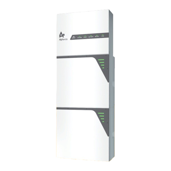
Page 17: Battery Pack Description
Battery pack appearance and dimensions SMILE-BAT-8.2PH SMILE-BAT-5PH Battery pack appearance and dimensions Battery Pack Dimension (W*H*D) SMILE-BAT-8.2PH (OUTDOOR) 580*820*230 mm SMILE-BAT-8.2PH (INDOOR) 580*730*230 mm Four LED indicators are provided on the display panel. ___________________________________________________________________ Alpha ESS Co., Ltd. Page 17 of 75... - Page 18 All the LED indicators are always on. When the battery is being charged and the SOC is between 80% and 100%, the fourth line of the LED indicator will flash every 3s. ___________________________________________________________________ Alpha ESS Co., Ltd. Page 18 of 75...
-
Page 19: Application Scenarios
Your Smart Energy Application Scenarios AlphaESS SMILE-S6-HV system (include SMILE-S6-HV-INV and SMILE-BAT- 8.2PH) can be applied in DC-coupled systems (mostly new installation), AC-coupled systems (mostly retrofit) and Hybrid-coupled systems (mostly retrofit, and PV capac- ity increase), as the following scheme show: DC-coupled Storage System–Scheme... -
Page 20: Storage
6 months should be recharged timely. 10. If a lithium battery is stored for a long time, capacity loss may occur. After a lithium battery is stored for 12 months in the recommended storage temperature, the ___________________________________________________________________ Alpha ESS Co., Ltd. Page 20 of 75... - Page 21 65~75% of the SOC. For example, they can be recharged every 6 months at least, and must be recharged to at least 50% of the SOC. ___________________________________________________________________ Alpha ESS Co., Ltd. Page 21 of 75...
-
Page 22: Unpacking
Scope of Delivery Check the scope of delivery for completeness and any externally visible damage. Contact your distributor if the scope of delivery is incomplete or damaged. SMILE-S6-HV-INV Hybrid Inverter Inverter Wall Anchor Inverter... -
Page 23: Mounting
• SMILE-S6-HV-INV (OUTDOOR) and SMILE-BAT-8.2PH (OUTDOOR) are suitable for indoor and outdoor use. SMILE-S6-HV-INV (INDOOR) and SMILE-BAT-8.2PH (INDOOR) are suitable for only indoor use. • Do not install the inverter in a place where a person can easily touch it because its housing and heatsink are hot during operation. - Page 24 In residential areas, do not mount the inverter on drywalls or walls made of similar materials which have a weak sound insulation performance because the noise generated by the inverter is noticeable. ___________________________________________________________________ Alpha ESS Co., Ltd. Page 24 of 75...
- Page 25 Your Smart Energy Mounting Angle and Stack Requirement SMILE-BAT-8.2PH should be floor-mounted. SMILE-S6-HV-INV should be wall-mounted. The installation angle requirement is as follow: • Do not mount the battery pack and inverter at forward tilted, back tilted, side tilted, horizontal, or upside down positions.
-
Page 26: Preparing Tools And Instruments
Cord end terminal PV-MS-HZ open-end PV-CZM-22100) crimper wrench) Vacuum cleaner Heat shrink tubing Heat gun Marker Measuring tape Bubble or digital level Personal Safety gloves Safety goggles Anti-dust respirator protective equipment Safety shoes ___________________________________________________________________ Alpha ESS Co., Ltd. Page 26 of 75... -
Page 27: Mounting The 8.2Ph And Inverter
4. After cleaning the dust and other objects from the two holes, place 2 wall anchors into the holes, then attach the battery wall bracket to the wall by using the SW10 hexagon sleeve. Please use a level to ensure that the wall bracket is horizontal. ___________________________________________________________________ Alpha ESS Co., Ltd. Page 27 of 75... - Page 28 Expansion wiring please refer to Chapter 7.8. 1) If you will install extra batteries by side, please repeat steps 1-6 and keep the distance between two batteries greater than 300mm. The space between the ___________________________________________________________________ Alpha ESS Co., Ltd. Page 28 of 75...
- Page 29 3) Place the battery positioning paper plate against the wall and the bottom with notch against the first battery pack. Repeat steps 1-7. 4) The bottom limit holes of the second battery will match the top screws of the first battery. ___________________________________________________________________ Alpha ESS Co., Ltd. Page 29 of 75...
- Page 30 2. Cover the top of the battery with plastic bag and drill 5 holes on the wall with drill Φ10, insert 5 screw anchors into the drill holes. ___________________________________________________________________ Alpha ESS Co., Ltd. Page 30 of 75...
- Page 31 PC gaskets to adjust it. 5. Tighten the wall bracket and the inverter with screw M6*16 (X 2) (tool: T20 screw- driver, torque: 3.0Nm). 6. Make electrical connection (please refer to Section 错误!未找到引用源。 Electrical Connection). ___________________________________________________________________ Alpha ESS Co., Ltd. Page 31 of 75...
-
Page 32: Mounting The Wifi Module
1. Remove the WiFi cover from the left of the inverter (tool: T20 screwdriver). 2. Tighten the WiFi module on the inverter with screw M4*12 (X2) (tool: T20 screw- driver, torque: 2.0 Nm). ___________________________________________________________________ Alpha ESS Co., Ltd. Page 32 of 75... -
Page 33: Electrical Connection
The cable colors shown in the electrical connection diagrams provided in this chapter are for reference only. Select cables in accordance with local cable specifi- cations (green-and-yellow cables are only used for PE). ___________________________________________________________________ Alpha ESS Co., Ltd. Page 33 of 75... -
Page 34: Overview Of The Connection Area
CT, DRM, LAN, AUX ) Backup connection port Grid connection port Connection point for an additional grounding Connection port for the WiFi module 1 positive and 1 negative BAT power connectors Battery breaker ___________________________________________________________________ Alpha ESS Co., Ltd. Page 34 of 75... -
Page 35: Preparing Cables
4 ~ 6 mm Cat5e, FTP, UV-resistant by the installer (AWG26~AWG24) for outdoor use) Multiple-core outdoor shielded Purchased ※3 0.1 ~1.3 mm Signal cable 4 ~ 6 mm twisted pair cable by the installer ___________________________________________________________________ Alpha ESS Co., Ltd. Page 35 of 75... - Page 36 PE cable copper cable by the installer ※1 For CT communication connection with inverter. ※2 For CAN/RS485, LAN, Meter, DRM communication connection with inverter. ※3 For AUX communication connection with inverter ___________________________________________________________________ Alpha ESS Co., Ltd. Page 36 of 75...
-
Page 37: Connecting Additional Grounding
Connect the ground points between the battery and the inverter to ensure that the battery and the inverter have been grounded, as shown in the figure below. a) SMILE-BAT-8.2PH (OUTDOOR) M5*10 Screw (×2) b) SMILE-BAT-8.2PH (INDOOR) ___________________________________________________________________ Alpha ESS Co., Ltd. Page 37 of 75... -
Page 38: Ac Connection
2. Lead the AC cable through the cable gland of the AC connection cover, don’t tighten the pressure cap of the cable gland. Grid cable must pass through magnetic ring which is provided as inverter accessory. ___________________________________________________________________ Alpha ESS Co., Ltd. Page 38 of 75... - Page 39 2 Nm with tool of cross recessed screwdriver. 6. Fix the AC connection cover tightly on the inverter and tighten the pressure caps of the two cable glands. ___________________________________________________________________ Alpha ESS Co., Ltd. Page 39 of 75...
- Page 40 Australia and New Zealand Where an external residual current device (RCD) is required in a TT or TN-S sys- tem, please install a residual current device which trips at a residual current of 30mA. ___________________________________________________________________ Alpha ESS Co., Ltd. Page 40 of 75...
- Page 41 ∙ If you use the extra PV inverter, the system is suitable for AC or Hybrid mode. 1. DTSU666-3*230V 5A: Three-phase meter (without CT) connection Wiring at single-phase home Wiring at three-phase home 2. DTSU666-100/40mA: Three-phase meter (with 3 or 6 CTs) connection Wiring at single-phase home ___________________________________________________________________ Alpha ESS Co., Ltd. Page 41 of 75...
- Page 42 NOTE: If you have extra PV inverter in the whole system, with two set CTs, you don’t need the second CT meter. One set CT is used for the grid side and another set for PV inverter side. ___________________________________________________________________ Alpha ESS Co., Ltd. Page 42 of 75...
- Page 43 “Grid Meter” and “PV side meter” to turn the “Meter” green. Step 2: Click “Save” and wait a few minutes to refresh the page. When the “Meter Model” displays DTSU666 model, the setting is successful. ___________________________________________________________________ Alpha ESS Co., Ltd. Page 43 of 75...
- Page 44 Click “Submit” and enter the “System information” page to check the meter model. The setting is successful if meter model is DTSU666-100/40mA. NOTE: It is forbidden to tick CT to modify the CT ratio. ___________________________________________________________________ Alpha ESS Co., Ltd. Page 44 of 75...
- Page 45 Your Smart Energy ___________________________________________________________________ Alpha ESS Co., Ltd. Page 45 of 75...
- Page 46 For AC-coupled systems and Hybrid-coupled systems, another PV-CT is needed to buy. Buckle the PV-CT on the live wire of the PV inverter connecting point and insert the registered jack of the PV-CT cable into the PV-CT port on the SMILE-S6-HV-INV. NOTE: The arrow of the CT should point to the grid port of the inverter from the grid or the PV inverter.
- Page 47 The neutral connector should be connected like above. Three/single-phase meter (Contain off-grid switching) Description Maximum current per phase Backup Box Backup Box-PLUS 1) Backup Box Connection Backup Box connection at single-phase home ___________________________________________________________________ Alpha ESS Co., Ltd. Page 47 of 75...
- Page 48 Your Smart Energy Backup Box connection at three-phase home ___________________________________________________________________ Alpha ESS Co., Ltd. Page 48 of 75...
- Page 49 Your Smart Energy 2) Backup Box-PLUS Connection Backup Box-PLUS connection at single-phase home Backup Box-PLUS connection at three-phase home ___________________________________________________________________ Alpha ESS Co., Ltd. Page 49 of 75...
-
Page 50: Battery Communication Connection
The system and the Demand Response Enabling Device (DRED) must be con- nected in the same network. Only DRM0 is available for SMILE-S6-HV. ___________________________________________________________________ Alpha ESS Co., Ltd. - Page 51 4) Take out 10 pin terminal block for AUX connection. For AUX position definition, please refer to the relative wiring document. 2. Place the COM connection cover against the inverter housing and tighten them. ___________________________________________________________________ Alpha ESS Co., Ltd. Page 51 of 75...
-
Page 52: Pv Connection
3. Ensure the correct polarity of power cable of the batteries before connecting to the inverter. 4. Connect the battery power cables to the respective connection ports of the inverter, a "click" sound means fully connection. Battery Pack Inverter ___________________________________________________________________ Alpha ESS Co., Ltd. Page 52 of 75... -
Page 53: Battery Pack Expansion Connection
Install extra SMILE-BAT-8.2PH batteries (outdoor) by side, without stack (outdoor) with stack Take out the terminal resistor provided by the inverter, insert it to the unused commu- nication port of the last battery. ___________________________________________________________________ Alpha ESS Co., Ltd. Page 53 of 75... - Page 54 Your Smart Energy SMILE-BAT-8.2PH (INDOOR) SMILE-BAT-8.2PH (OUTDOOR) ___________________________________________________________________ Alpha ESS Co., Ltd. Page 54 of 75...
-
Page 55: Wifi Setting
Download and Install APP 1.Android device users can download the APP through major Android application markets such as Google Play. 2.IOS device users can search for “AlphaESS” in AppStore and download the APP. AlphaESS-APP ___________________________________________________________________ Alpha ESS Co., Ltd. Page 55 of 75... -
Page 56: Overview Of Functions For Installer Account
This section is for users who have a system with a WiFi module. AlphaESS App supports network configuration, setting of the system basic parame- ter, and the viewing of system operation and configuration information. ___________________________________________________________________ Alpha ESS Co., Ltd. Page 56 of 75... - Page 57 Step 3: If your mobile phone hasn’t connected to the system’s hotspot, please open the Wi-Fi network list. Please find the hotspot named by the product SN ___________________________________________________________________ Alpha ESS Co., Ltd. Page 57 of 75...
- Page 58 For setting the system basic parameters, please refer to AlphaESS APP user guide on the official website. Safety Parameters Settings Procedure 1. Login the account; 2. Click ‘System Setup’; 3. Choose ‘Inverter Information’; 4. Choose corresponding ‘Safety parameter’ ___________________________________________________________________ Alpha ESS Co., Ltd. Page 58 of 75...
- Page 59 So please let the customer type in the most frequently used email address when register on Alpha Portal. The example email will be like the following if the earth fault happens. ___________________________________________________________________ Alpha ESS Co., Ltd. Page 59 of 75...
-
Page 60: Commissioning
OFF. The AC cable, PV cable, battery cable, and Cable connections communication cables are connected correctly, securely, and reliably. Unused power Unused power terminals are blocked by terminals watertight caps. ___________________________________________________________________ Alpha ESS Co., Ltd. Page 60 of 75... -
Page 61: Check The Running State
NOTICE During commissioning, if the LED indictors on the display panel of the inverter or the battery pack show red, please refer to Section 10.2 for troubleshooting. ___________________________________________________________________ Alpha ESS Co., Ltd. Page 61 of 75... -
Page 62: Powering Off The Product
4. Switch off the PV switch between the PV string and the inverter if there is any. 5. Switch off the AC breaker between the inverter and the load. 6. Switch off the AC breaker between the inverter and the grid. ___________________________________________________________________ Alpha ESS Co., Ltd. Page 62 of 75... -
Page 63: Maintenance And Troubleshooting
The heatsink and housing can get hot during operation. • During operation, do not touch any parts other than the cover of the inverter. • Wait approx. 30 minutes before cleaning until the heatsink has cooled down. ___________________________________________________________________ Alpha ESS Co., Ltd. Page 63 of 75... -
Page 64: Troubleshooting
3. After the inverter is powered off and waiting for 30 minutes, then restart it. If the fault still exists, contact ser- vice. Check the PV2 voltage. If it exceeds 585V, reduce the 100021 MPPT2_OVP number of PV modules ___________________________________________________________________ Alpha ESS Co., Ltd. Page 64 of 75... - Page 65 2. Restart the inverter to see if the fault still exists. If it still exists, contact service. 100040 INV_HW_OCP Restart the inverter to see if the fault still exists. If it still ex- Output_DC_ ists, contact service. 100041 over_voltage ___________________________________________________________________ Alpha ESS Co., Ltd. Page 65 of 75...
- Page 66 110006 over_temperature_alarm 3. After the inverter is powered off and waiting for 30 minutes, then restart it. If the fault still exists, contact ser- vice. ___________________________________________________________________ Alpha ESS Co., Ltd. Page 66 of 75...
- Page 67 Cell overvoltage Stop discharging and call service Cell under voltage immediately. Stop discharging until this code is Low-temperature eliminated and wait for the charge temperature to rise. ___________________________________________________________________ Alpha ESS Co., Ltd. Page 67 of 75...
- Page 68 5 times within 10 seconds, the BMS will be forced to turn on the MOSFET of dis- charge so that the inverter can detect the battery open voltage and charge the battery. ___________________________________________________________________ Alpha ESS Co., Ltd. Page 68 of 75...
-
Page 69: Uninstallation & Return
Dispose of the packaging and replaced parts according to the rules at the installation site where the device is installed. Do not dispose the inverter and the battery pack with normal domestic waste. ___________________________________________________________________ Alpha ESS Co., Ltd. Page 69 of 75... -
Page 70: Specification
Your Smart Energy 12. Specification 12.1 Datasheet of Hybrid Inverter SMILE-S6-HV-INV SMILE-S6-HV-INV (OUT- SMILE-S6-HV-INV (IN- Item DOOR) DOOR) Input DC (PV side) Recommended Max. PV Power 9000 W 7500 W Max. PV Input Voltage 580 V Rated Voltage 360 V... - Page 71 General data Dimensions (W*H*D) 580*440*230 mm Weight 25 kg Topology Transformerless Operation Temperature Range -25 ~ +60 ° C Ingress Protection IP65 IP21 Noise Emission <30 dB(A) @1m Cooling Concept Natural convection ___________________________________________________________________ Alpha ESS Co., Ltd. Page 71 of 75...
-
Page 72: Datasheet Of Battery Pack Smile-Bat-8.2Ph
System voltage, current, cell voltage, Monitoring Parameters cell temperature, PCBA temperature Communication CAN and RS485 compatible Safety IEC62619(Cell), IEC 62619(Pack) Transportation UN38.3 * Max. charge/discharge current derating will occur related to temperature and SOC. ___________________________________________________________________ Alpha ESS Co., Ltd. Page 72 of 75... -
Page 73: Appendix
Your Smart Energy Appendix A1. Communication Connection Figure Connect the CT Connect the meter ___________________________________________________________________ Alpha ESS Co., Ltd. Page 73 of 75... - Page 74 Australia Regional standards C10/C11 Belgium TOR Erzeuger Austria CEI 0-21 Italy NRS 097-2-1 South Africa G98/G99 Britain 50Hz default 50Hz grid For 50Hz grid region G98/G99-IE Ireland EN50549 NC Rfg Poland ___________________________________________________________________ Alpha ESS Co., Ltd. Page 74 of 75...
- Page 75 ∙ If the extra PV inverter is not used, the system is suitable for DC mode. ∙ If you have the extra PV inverter, the system is suitable for AC or Hybrid mode. ___________________________________________________________________ Alpha ESS Co., Ltd. Page 75 of 75...
Need help?
Do you have a question about the SMILE-S6-HV and is the answer not in the manual?
Questions and answers