Advertisement
Quick Links
IMPORTANT: pleAse reAD these instructions cArefully. note the sAfe operAtionAl reQuirements, wArnings AnD cAutions. use this
proDuct correctly AnD with cAre for the purpose for which it is intenDeD. fAilure to Do so mAy cAuse DAmAge AnD/or personAl
injury AnD will invAliDAte the wArrAnty. keep these instructions for future use.
1. sAfety instructions
Disconnect the gauge from the air supply before changing accessories, servicing or performing any maintenance.
Maintain the gauge in good condition (use an authorised service agent), and keep the gauge clean for best and safest performance.
Replace or repair damaged parts. Use recommended parts only. Unauthorised parts may be dangerous and will invalidate the warranty.
Locate gauge in a suitable work area, keep area clean and tidy and free from unrelated materials and ensure there is adequate lighting.
Keep children and unauthorised persons away from the work area.
Do not direct gauge outlet at yourself or at other persons or animals.
Do not carry by the hose, or yank the hose from the air supply.
Do not use the gauge for a task which it is not designed to perform.
Do not operate the gauge when you are tired, under the influence of alcohol, drugs or intoxicating medication.
Do not operate the gauge if any parts are missing or the gauge is damaged, as this may cause failure and/or personal injury.
2. introDuction & specificAtions
The SEALEY SA37/93.V3 & SA37/94.V2 Professional Air Line Gauges are designed for strength and durability, for use on garage forecourts and in tyre fitting bays. For trouble-free
operation it is essential that the gauge is correctly installed and periodically checked for correct operation.
both models:
supply pressure:
Maximum 13.8 bar (200psi)
Min. recommended 6.9 bar (100psi)
supply connection:
1/4"BSP (female) connection port.
body construction:
Die-cast aluminium with steel operating lever and
impact absorbing rubber bumper.
tyre pressure range:
0-9.6 bar (0-138psi) standard.
gauge:
Linear, with magnifying viewing window. Accuracy
to 86/217/EEC.
3. instAllAtion
3.1
instAllAtion for both moDels
3.1.1
Air supply - mAximum pressure 13.8 bAr (200psi)
The supply must be clean and dry - use a suitable filter/water trap if necessary. The supply pressure at the gauge inlet should ideally be 10.5 - 12.5 bar (150 - 180psi). The gauge
will
function correctly with supply pressures down to 7 bar (100psi), but inflation times will be increased.
note:
Maximum tyre inflation pressure cannot exceed the supply pressure.
3.1.2
pipe work
Copper or galvanised steel tube is recommended for the supply line from the compressor. The number of bends in the line should be kept to a minimum and no pockets or low points
should be present to allow water to accumulate. Blow the line clear of any debris and drain off any accumulated water before making the final connection to the gauge.
3.2
flexible hose - moDel sA37/93
The flexible line to the gauge should be properly rated for the duty and supply pressure - hose to BS5118 class 2 is recommended. A 1/4"BSP Taper (male) connection is required to
connect to the gauge.
3.3
flexible hose - moDel sA37/94 (supplieD - 2.75 metres)
Supplied hose meets required standards for use on commercial and agricultural tyres. If an additional extension hose is required it must be properly rated for the duty and supply
pressure - hose to BS5118 class 2 is recommended. A 1/4"BSP Taper (male) connection is required to connect to the gauge.
4. operAtion
4.1
tyre pressure
Hold the gauge with the thumb on the operating lever and place the tyre connector onto the tyre valve. Momentarily depress the lever fully, then release to display tyre pressure.
When reading the pressure, hold the gauge "flat" with respect to the eye to minimise error. Ensure top and bottom red lines are exactly aligned to give an accurate reading.
4.2
to inflAte
Fully depress lever for an appropriate period: release lever to display new pressure.
4.3
to DeflAte
Depress lever half-way (until air can be heard escaping) for an appropriate period. Fully depress lever momentarily then release to display new pressure.
importAnt - AlwAys fully Depress lever momentArily before reADing tyre pressure.
5. fAult finDing guiDe
This air line gauge has been engineered to give years of trouble-free service. Major faults are often due either to prolonged mistreatment or to a dirty, excessively wet air supply. The
following guide will enable the operator or service engineer to diagnose and cure any problems which may arise.
5.1
Air leAks from tyre connector
The seals should be replaced when it becomes difficult to obtain an easy, positive airtight seal on a tyre valve. Spare seal kits are available from distributors.
5.2
DAmAgeD flexible hose (gAuge to tyre connector)
The complete hose assembly should be replaced immediately if any sign of deep chafing or cracking appears. Ensure that the centred filter in the gauge outlet port does not become
dislodged during replacement.
5.3
errAtic high gAuge reADings or stiff, jerky lever operAtions
Caused by a stiff or damaged valve assembly. If not cured by oiling the valve mechanism then replace the valve assembly.
5.4
slow tyre inflAtion
Caused by:.................Low supply pressure, or ........blocked inlet filter, or.......damaged valve mechanism.
5.5
errAtic low gAuge reADings AnD/or sluggish gAuge operAtion - gAuge Does not return to zero
Caused by stiff or damaged gauge mechanism. The gauge must be returned to an authorised repair centre as special equipment is required to re-check the calibration of the gauge
after repair.
6. mAintenAnce & service
perioDic checks AnD mAintenAnce
For long service and accuracy, the following actions should be carried out at the recommended intervals.
6.1
weekly - check operAtion
The gauge should be checked weekly for correct operation. Look for smooth lever operation and fast, smooth gauge movements. Check for leaks from tyre connector seals, and for
chafing or wear of the flexible hoses. Any problems should be immediately rectified to ensure calibration is not affected.
6.2
QuArterly - check cAlibrAtion
We recommend the accuracy of the gauge be checked against a calibrated 'master' gauge every 3 months, or at shorter intervals depending on operator's own quality procedures
manual.
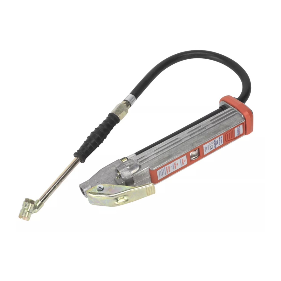
professionAl Air line gAuge
Model SA37/93.V3:
hose:
500mm hose
tyre connector:
Twin push-on air connector
Model SA37/94.V2:
hose:
2.75m hose
tyre connector:
Clip-on air connector
InSTRuCTIOnS FOR:
sA37/93.v3
MODELS:
& sA37/94.v2
Part No:
144/RHA2031
SA37/C/O
Part No:
144/RHA2121
144/C02E0 33
SA37/93.V3 & SA37/94.V2 - 3 - 08/04/10
Advertisement

Related Manuals for Sealey SA37/93.V3


Summary of Contents for Sealey SA37/93.V3
- Page 1 2. introDuction & specificAtions The SEALEY SA37/93.V3 & SA37/94.V2 Professional Air Line Gauges are designed for strength and durability, for use on garage forecourts and in tyre fitting bays. For trouble-free operation it is essential that the gauge is correctly installed and periodically checked for correct operation.
- Page 2 Guarantee is 12 months from purchase date, proof of which will be required for any claim. informAtion: For a copy of our latest catalogue and promotions call us on 01284 757525 and leave your full name and address, including postcode. sole uk Distributor, sealey group, www.sealey.co.uk...
- Page 3 Air line gauge model nos: sA37/93.v3 & sA37/94.v2 This Air Line Gauge has been calibrated in the normal working position on test equipment with an accuracy that is traceable to the UK National Standard through the National Physical...