Canon SELPHY CP770 Service Manual
Compact photo printer
Hide thumbs
Also See for SELPHY CP770:
- Printing manual (32 pages) ,
- Specifications (2 pages) ,
- User manual (82 pages)
Table of Contents
Advertisement
Quick Links
Advertisement
Chapters
Table of Contents

Related Manuals for Canon SELPHY CP770


Summary of Contents for Canon SELPHY CP770
- Page 2 Copyright: All copyrights in the content of this Service Manual are owned or controlled by Canon Inc. You are not permitted to copy, reproduce, download, modify, adapt or translate in any way the content of this Service Manual for any purpose other than the purpose contemplated herein without prior written consent of Canon Inc.
-
Page 3: Table Of Contents
CONTENTS 1 Overview Summary of Main Features ..........................1 Comparison of Main Features ..........................4 2 Exterior Exterior Photos ..............................6 5-View Diagram ..............................7 Nomenclature ..............................10 3 Specifications Product Specifications............................12 System Diagram ..............................16 Functions Available in Each Printing Mode ...................... 17 4 Accessory Specifications Paper Cassettes .............................. -
Page 4: Overview
1 Overview SELPHY-CP770 is the flagship model of the new CP series that incorporates the concept of a design for everyday use and a storage solution, targeting the user group of young families. The SELPHY-CP760 succeeds the CP series design. In order to reach a wide range of users, efforts have been made to improve the user friendliness, and functions have been added. - Page 5 • Layouts: 1 / 2 / 4 / 8-up layout and Index print Direct print (from a camera) support • Changes the default connection to PictBridge • Canon Direct Print connection Wireless printing • Bluetooth Bluetooth unit BU-30 (sold separately) required •...
- Page 6 Others Higher quality and high speed printing from a memory card or a camera with PictBridge LCD monitor • 2.5-inch type TFT color LCD monitor Basket-type accessory storage case (SELPHY-CP770) Compact power adapter CA-CP200 (white) , which color matches with the printer Specifications are the same as those of CA-CP200 Battery powered operation (SELPHY-CP770) •...
-
Page 7: Comparison Of Main Features
Automatic dynamic-range correction Correction) • Optimize automatically with the camera when print- Image Quality Adjustment • Optimize automatically with the camera when print- ing using Canon Direct Print ing using Canon Direct Print Adobe RGB support Adobe RGB support Three slots Card Slots •... - Page 8 Automatic dynamic-range correction Correction) • Optimize automatically with the camera when print- Image Quality Adjustment • Optimize automatically with the camera when print- ing using Canon Direct Print ing using Canon Direct Print Adobe RGB support Adobe RGB support Three slots Card Slots •...
-
Page 9: Exterior
2 Exterior 2-1 Exterior Photos • SELPHY-CP770 With basket (storage case) • SELPHY-CP760... -
Page 10: 5-View Diagram
2-2 5-View Diagram SELPHY-CP770 • Unit : mm (inch) Normal Dimentions 248.0 (9.76) - Page 11 • Basket (Storage case) Unit : mm (inch) Normal Dimentions 276.0 (10.9) 174.0 (6.85) 154.1 (6.07) 224.0 (8.82)
- Page 12 • SELPHY-CP760 Unit : mm (inch) Normal Dimentions 180.0 (7.09)
-
Page 13: Nomenclature
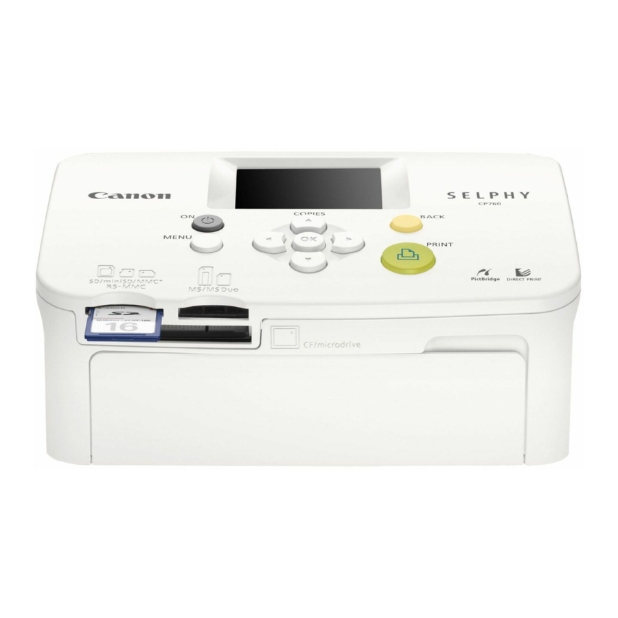
2-3 Nomenclature • SELPHY-CP770... - Page 14 • SELPHY-CP760...
-
Page 15: Specifications
The values in the table are for images shot at the 4:3 aspect ratio with models of the Power- Shot series and IXY DIGITAL series. When using Canon Direct Print, print size is 100.0 x 150.0 mm (3.94 x 5.91 in.) and photo is aligned with the left side of the paper. - Page 16 • Date stamp and file number follow DPOF setting with the camera (not selectable on the printer). Direct Printing from a Camera Available (Canon digital camera, PictBridge compliant camera) Printing from a Computer Available • Installation of the printer driver from the supplied Compact Photo Printer Solution Disk is required.
- Page 17 Transition Effects Not available Auto Rotate Not available Interface PictBridge compliant camera / Canon Direct Print compliant camera: Type A connec- Computer: Type B connector Wireless Infrared (IrDA, IrSimple) (CP770 only) Images are translated with IrOBEX, IrMC by vNOTE Bluetooth •...
- Page 18 Printer Specifications Operating Temperature 5 – 40°C (41 – 104°F) Operating Humidity 20 – 80% Power Source Compact Power Adapter CA-CP200 Battery Pack NB-CP2L Charging Time (when using Approx. 4 hours (charged in main printer unit) NB-CP2L) Power Consumption 60 W or less (Standby: 4 W or less) Dimensions (excluding protrusions) CP770 (Printer): 248.0 x 156.4 x 77.3 mm (9.76 x 6.16 x 3.04 in.) CP770 (With basket (storage case)): 276.0 x 174.0 x 205.8 mm (10.9 x 6.85 x 8.10 in.)
-
Page 19: System Diagram
3-2 System Diagram CP770 SELPHY SELPHY CP770/CP760 CP770/CP760 CP770... -
Page 20: Functions Available In Each Printing Mode
3-3 Functions Available in Each Printing Mode Printing Directly from a Memory Card Printing from a Camera Wireless Printing Computer Print Print all Canon DPOF Infrared Connection selected images at PictBridge Direct Bluetooth Print*1 (CP770 only) images one time Print Date *2 ○... -
Page 21: Accessory Specifications
4 Accessory Specifications 4-1 Paper Cassettes 4-1-1 PCP-CP300 (for postcard size) Appearance Diagram Unit : mm (inch) 16.2 (0.64) 113.7 (4.48) Dimensions 113.7 x 191.5 x 16.2 mm (4.48 x 7.54 x 0.64 in.) Weight Approx. 135 g (4.76 oz.) 4-1-2 PCL-CP300 (for L size) Appearance Diagram Unit : mm (inch) -
Page 22: Ink Cassettes
4-1-3 PCC-CP300 (for card size) Appearance Diagram Unit : mm (inch) 16.2 (0.64) 113.7 (4.48) Dimensions 113.7 x 104.9 x 16.2 mm (4.48 x 4.13 x 0.64 in.) Weight Approx. 78 g (2.75 oz.) Including full page label sheets, 8-label sheets 4-1-4 PCW-CP100 (for wide size) Dimensions 239.5 x 111.6 x 15.5 mm (9.43 x 4.39 x 0.61 in.) -
Page 23: Compact Power Adapter Ca-Cp200 (White)
4-4 Compact Power Adapter CA-CP200 (white) 100 - 240 V AC (50/60 Hz) Rated Input 1.5 A (100 V) - 0.75 A (240 V) Rated Output 24 V DC, 2.2 A Operating Temperatures 0 - 45°C (32 - 113°F) 122.0 x 60.0 x 30.5 mm (4.80 x 2.36 x 1.20 in.) Dimensions (excluding power cord) Weight... -
Page 24: Accessory Compatibility
– – – – – – – – – For use with Canon digital cameras and video cameras that support Canon Direct Print or PictBridge. When connecting via PictBridge with another manufacturer's camera, use the cable specified for that camera. - Page 25 Copyright: All copyrights in the content of this Service Manual are owned or controlled by Canon Inc. You are not permitted to copy, reproduce, download, modify, adapt or translate in any way the content of this Service Manual for any purpose other than the purpose contemplated herein without prior written consent of Canon Inc.
- Page 26 CONTENTS (SELPHY CP770) 1.1 MAIN BLOCK, BASKET UNIT ------------------------------------------------------------------------------------------- 1 1.2 ENERGY LABEL ------------------------------------------------------------------------------------------------------------ 2 1.3 BATTERY CASE COVER -------------------------------------------------------------------------------------------------- 3 1.4 PAPER CASSETTE DOOR, INK CASSETTE DOOR ----------------------------------------------------------------- 4 1.5 TOP COVER ASS’Y-(1) ---------------------------------------------------------------------------------------------------- 5 1.6 TOP COVER ASS’Y-(2) ---------------------------------------------------------------------------------------------------- 6 1.7 FRONT INNER COVER, CASSETTE INNER COVER, INK CASSETTE DOOR HOOK ---------------------- 7...
-
Page 27: Main Block, Basket Unit
MAIN BLOCK, BASKET UNIT (1) Unhook the two clasps, and separate the MAIN BLOCK from the BASKET UNIT. (1) MAIN BLOCK Clasp Clasp (1) BASKET UNIT... -
Page 28: Energy Label
ENERGY LABEL (1) Peel off the ENERGY LABEL. NOTE (Assembly) Attach the ENERGY LABEL to the position shown in the figure. NOTE (Assembly) (1) ENERGY LABEL COPIES MENU BACK PRINT 24mm ENERGY 45mm LABEL... -
Page 29: Battery Case Cover
BATTERY CASE COVER (1) Push the BATTERY RELEASE BUTTON in the direction of the arrow and remove the BATTERY CASE COVER. (1) BATTERY CASE COVER (1) BATTERY RELEASE BUTTON... -
Page 30: Paper Cassette Door, Ink Cassette Door
PAPER CASSETTE DOOR, INK CASSETTE DOOR (1) Remove the PAPER CASSETTE DOOR. (2) Remove the INK CASSETTE DOOR. CAUTION CAUTION Remove the INK CASSETTE DOOR Remove the PAPER CASSETTE DOOR by by twisting it slightly in the direction bending it slightly in the direction of the arrow. of the arrow. -
Page 31: Top Cover Ass'y-(1)
TOP COVER ASS’Y-(1) (1) Remove the four screws. CAUTION The slots in the top of the screws can be easily rounded off, so use the appropriate size driver for these screws and be careful when removing them. - Page 32 TOP COVER ASS’Y-(2) (1) Disengage the two claws, and open the TOP COVER ASS’Y in the direction of the arrow. (2) Disconnect the two connectors, and remove the TOP COVER ASS’Y. (2) TOP COVER ASS'Y CAUTION Be careful not to damage the flexible boards.
-
Page 33: Front Inner Cover, Cassette Inner Cover, Ink Cassette Door Hook
FRONT INNER COVER, CASSETTE INNER COVER, INK CASSETTE DOOR HOOK (1) Remove the FRONT INNER COVER. (2) Remove the CASSETTE INNER COVER. (3) Remove the INK CASSETTE DOOR HOOK (2 pieces). CASSETTE INNER COVER FRONT INNER COVER INK CASSETTE DOOR HOOK (2 pieces) INK CASSETTE DOOR HOOK... -
Page 34: Irda Window
IRDA WINDOW (1) Disengage the two claws, and remove the IRDA WINDOW. IRDA WINDOW Claw Claw... -
Page 35: Main Plate, Main Sheet
MAIN PLATE, MAIN SHEET (1) Remove the three screws, and remove the MAIN PLATE and the MAIN SHEET. NOTE (Assembly) Fold the MAIN SHEET as shown in the figure. NOTE (Assembly) MAIN PLATE MAIN SHEET Fold MAIN SHEET Fold MAIN SHEET... -
Page 36: Main Ass'y, Bottom Ass'y-(1)
1.10 MAIN ASS’Y, BOTTOM ASS’Y-(1) (1) Remove the three screws. (2) Disconnect the two connectors. NOTE (Assembly) When assembling, tighten the screws in order to the screw holes A, B, and C. Connector Connector Screw hole B Screw hole A Screw hole C... -
Page 37: Main Ass'y, Bottom Ass'y-(2)
1.11 MAIN ASS’Y, BOTTOM ASS’Y-(2) (1) Separate the MAIN ASS’Y and the BOTTOM ASS’Y. CAUTION Never hold the area around the front plate when separating or reassembling the MAIN ASS’Y and the BOTTOM ASS’Y. Be sure to hold the area around the cassette guide. NOTE (Assembly) After installing the MAIN ASS’Y, confirm that the three dowels and the rib are correctly engaged. -
Page 38: Bottom Cover Ass'y, Battery Case Ass'y, Battery Terminal Ass'y
1.12 BOTTOM COVER ASS’Y, BATTERY CASE ASS’Y, BATTERY TERMINAL ASS’Y (1) Remove the two screws, and remove the BATTERY CASE ASS’Y and BATTERY TERMINAL ASS’Y together as an assembled unit from the BOTTOM COVER ASS’Y. (2) Remove the two screws, and separate the BATTERY TERMINAL ASS’Y from the BATTERY CASE ASS’Y. -
Page 39: Main Pcb Ass'y, Print Unit
1.13 MAIN PCB ASS’Y, PRINT UNIT (1) Disconnect the two connectors. (2) Disconnect the connector, and separate the MAIN PCB ASS’Y and the PRINT UNIT. NOTE (Assembly) Using the edge of the head heatsink as a guide, fold the FLAT CABLE as shown in the figure. Set the INK CASSETTE and check if it comes out smoothly. -
Page 40: Energy Label
ENERGY LABEL (1) Peel off the ENERGY LABEL. NOTE (Assembly) Attach the ENERGY LABEL to the position shown in the figure. (1) ENERGY NOTE (Assembly) LABEL 21mm ENERGY LABEL 13mm... -
Page 41: Ink Cassette Door, Paper Cassette Door
INK CASSETTE DOOR, PAPER CASSETTE DOOR (1) Remove the INK CASSETTE DOOR. (2) Remove the PAPER CASSETTE DOOR. CAUTION Remove the INK CASSETTE DOOR or the PAPER CASSETTE DOOR by bending it slightly in the direction of the arrow as shown in the figure. (2) PAPER CASSETTE (1) INK CASSETTE... -
Page 42: Top Cover Ass'y-(1)
TOP COVER ASS'Y-(1) (1) Remove the four screws. CAUTION The slots in the top of the screws can be easily rounded off, so use the appropriate size driver for these screws and be careful when removing them. - Page 43 TOP COVER ASS'Y-(2) (1) Disengage the two claws, and open the TOP COVER ASS'Y in the direction of the arrow. (2) Disconnect the two connectors, and remove the TOP COVER ASS'Y. (2) TOP COVER ASS'Y CAUTION Be careful not to damage the flexible boards.
-
Page 44: Ink Cassette Door Hook
INK CASSETTE DOOR HOOK (1) Remove the INK CASSETTE DOOR HOOK (2 pieces). (1) INK CASSETTE DOOR HOOK (1) INK CASSETTE DOOR HOOK INK CASSETTE DOOR HOOK... -
Page 45: Main Ass'y, Bottom Ass'y-(1)
MAIN ASS'Y, BOTTOM ASS'Y-(1) (1) Remove the three screws. (2) Disconnect the connector. NOTE (Assembly) When assembling, tighten the screws in order to the screw holes A, B, and C. Connector Screw hole B Screw hole A Screw hole C... - Page 46 MAIN ASS'Y, BOTTOM ASS'Y-(2) (1) Separate the MAIN ASS'Y and the BOTTOM ASS'Y. CAUTION Never hold the area around the front plate when separating or reassembling the MAIN ASS'Y and the BOTTOM ASS'Y. Be sure to hold the area around the cassette guide. NOTE (Assembly) After installing the MAIN ASS'Y, confirm the three dowels and rib are correctly engaged.
-
Page 47: Rear Cover Ass'y, Bottom Cover Ass'y
REAR COVER ASS’Y, BOTTOM COVER ASS'Y (1) Separate the REAR COVER ASS’Y from the BOTTOM COVER ASS’Y. (1) REAR COVER ASS’Y (1) BOTTOM COVER ASS’Y... -
Page 48: Main Plate, Main Sheet
MAIN PLATE, MAIN SHEET (1) Remove the three screws, and remove the MAIN PLATE and the MAIN SHEET. NOTE (Assembly) Fold the MAIN SHEET as shown in the figure. NOTE (Assembly) MAIN PLATE MAIN SHEET Fold MAIN SHEET Fold MAIN SHEET... -
Page 49: Main Pcb Ass'y, Print Unit
2.10 MAIN PCB ASS’Y, PRINT UNIT (1) Disconnect the two connectors. (2) Disconnect the connector, and separate the MAIN PCB ASS’Y and the PRINT UNIT. NOTE (Assembly) Using the edge of the head heatsink as a guide, fold the FLAT CABLE as shown in the figure. Set the INK CASSETTE and check if it comes out smoothly. - Page 50 Copyright: All copyrights in the content of this Service Manual are owned or controlled by Canon Inc. You are not permitted to copy, reproduce, download, modify, adapt or translate in any way the content of this Service Manual for any purpose other than the purpose contemplated herein without prior written consent of Canon Inc.
- Page 51 CONTENTS • SELPHY CP770 1. Head Voltage Adjustment ------------------------------------------------------------------------------------------------------1 1.1 Required Equipment --------------------------------------------------------------------------------------------------1 1.2 Preparation Before Adjustment -------------------------------------------------------------------------------------1 1.3 Adjustment Procedure ------------------------------------------------------------------------------------------------2 2. Checking and Changing the Total Number of Printed Sheets -------------------------------------------------------------5 2.1 Required Equipment --------------------------------------------------------------------------------------------------5 2.2 Procedure for Checking and Changing ----------------------------------------------------------------------------5 •...
-
Page 52: Selphy Cp770
English 1.1 Required Equipment 1 SELPHY CP770 that is confirmed to operate normally. (Prepare a SELPHY CP770 in addition to the SELPHY CP770 that is brought in for repair.) 2 SD Card in which the standard image (gry_0100.JPG in case of the file stored in Service Manual) is copied, which is supplied with this Service Manual. -
Page 53: Adjustment Procedure
1.3 Adjustment Procedure (1) Read the resistance value (Ω) at the specified position in the illustration below. Headunit Resistance value indication position (2) Calculate the Voltage value as below. Note: The calculation formula differs depending on the identification number indicated on the head unit. - Page 54 Flexible cable (4) Attach the screws and the connector removed in step (1), and then remove the TOP COVER SECTION. Connect the SELPHY CP770 and the digital camera with the interface cable to make direct printing pos- sible. (5) While Printing an arbitrary image from the digital camera, measure the voltage of the test points ( during printing, and adjust the volume (VR) so that the voltage value is within ±0.03 V of the voltage value...
- Page 55 (8) Confirm that the center density of the printed image is between the lower limit density and the higher limit density as shown. If the center density is between them, this is the end of the adjustment. If it is not, go to step (9) and the following steps.
-
Page 56: Checking And Changing The Total Number Of Printed Sheets
Sheets Printed Change Software” (Download from SSIS) 2.2 Procedure for Checking and Changing (1) Connect the SELPHY CP770 and the computer with the USB cable, and turn on the power to the SELPHY CP770. Double-click on CP770FVC.exe to start the software. - Page 57 (3) Enter the total number of printed sheets to change to in the box on the right side of “New Sheets” in the dialog box below, and click the [Overwrite] button. (4) Check the entered total number of printed sheets displayed in the dialog box below, and click the [OK] button.
-
Page 58: Selphy Cp760
2 SD Card in which the standard image (gry_0100.JPG in case of the file stored in Service Manual) is copied, which is supplied with this Service Manual. Copy it to the folder “***CANON” in the SD Card. (Select the DCF format.) 3 Digital camera which has Direct Print function. - Page 59 (2) Calculate the Voltage value as below. Note: The calculation formula differs depending on the identification number indicated on the head unit. There are two identification codes, KD27. MAIN PCB ASS’Y Identification code Test point I Identification code: KD27 Voltage value = (Resistance value x 0.0845) For example, when the resistance value is 2962 Ω...
- Page 60 (4) Attach the screws and the connector removed in step (1), and then remove the TOP COVER SECTION. Connect the SELPHY CP760 and the digital camera with the interface cable to make direct printing pos- sible. (5) While Printing an arbitrary image from the digital camera, measure the voltage of the test points ( during printing, and adjust the volume (VR) so that the voltage value is within ±0.03 V of the voltage value calculated in step (2).
-
Page 61: Checking And Changing The Total Number Of Printed Sheets
2. Checking and Changing the Total Number of Printed Sheets For SELPHY CP760, the total number of printed sheets can be checked and changed by using the soft- ware for checking and changing the total number of printed sheets. Perform this operation if the total number of printed sheets needs to be changed when repairs are made. - Page 62 (3) Enter the total number of printed sheets to change to in the box on the right side of “New Sheets” in the dialog box below, and click the [Overwrite] button. (4) Check the entered total number of printed sheets displayed in the dialog box below, and click the [OK] button.