Table of Contents
Advertisement
Advertisement
Table of Contents

Related Manuals for LI-COR Odyssey CLx


Summary of Contents for LI-COR Odyssey CLx
- Page 1 Odyssey® CLx Operator’s Manual...
- Page 3 CE Marking: This product (model number 9140) is a CE-marked product. For conformity information, contact LI-COR Support at http://www.licor.com/biotechsupport. Outside of the U.S., contact your local sales office or distributor. 德 CLX Odyssey CLx Imager Part Name Toxic and Hazardous Substances or Elements...
- Page 4 Notes on Safety LI-COR products have been designed to be safe when operated in the manner described in this manual. The safety of this product cannot be guaranteed if the product is used in any other way than is specified in this manual. The Odyssey®...
- Page 5 WARRANTY OF ANY KIND WITH REGARD TO THIS MATERIAL, INCLUDING, BUT NOT LIMITED TO THE IMPLIED WARRANTIES OF MERCHANTABILITY AND FITNESS FOR A PARTICULAR PURPOSE. LI-COR shall not be liable for errors contained herein or for incidental or consequential damages in connection with the furnishing, performance, or use of this material.
-
Page 6: Table Of Contents
Odyssey® Table of Contents Imager Chapter 1: Installation and Safety Information Safety Considerations Laser Safety Safety Interlocks Placement in the Laboratory Ambient Laboratory Conditions Instrument Ventilation Space Requirements Level the Imager Moving the Imager Chemical Safety Electrical Considerations Power Cords Power Switch Fuse Information Computer Connections and Networking... - Page 7 Cleaning the Scanning Surface Scanning Using Membranes Using Gels Using Multiwell Plates Scanning Slides Obtaining Technical Support Exporting Image Studio Software Log Files Finding Empiria Studio Software Log Files Chapter 4: Appendix Specifications Imaging System Operating Specifications Embedded Firmware Source Code Page 7...
-
Page 9: Chapter 1: Installation And Safety Information
Odyssey CLx lid is opened. The label shown in Figure 3-3 is affixed to the inside of the Odyssey CLx case at two locations; one near the laser/microscope assembly scanning bed, and the second on the cover that is used to seal the above mentioned assembly. - Page 10 Chapter 1: Installation and Safety Information CONFORMS TO UL STD 61010-1 CERTIFIED TO CAN/CSA STD C22.2 NO. 61010-1 THIS DEVICE COMPLIES WITH PART 15 OF THE FCC RULES. OPERATION IS SUBJECT TO THE FOLLOWING TWO CONDITIONS: (1) THIS DEVICE MAY NOT CAUSE HARMFUL INTERFERENCE, AND (2) THIS DEVICE MUST ACCEPT ANY INTERFERENCE Figure 3-1.
-
Page 11: Safety Interlocks
Odyssey CLx Imager. Ambient Laboratory Conditions Place the Odyssey CLx Imager away from external heat sources (furnaces, windows, etc.). Additional heating can cause high temperatures within the enclosure. Place the instrument away from sinks or other sources of water that pose a shock hazard. Recommended operating conditions are 15 - 35 °C and a dew point not greater than 20 °C to prevent condensation on the laser/microscope assembly... -
Page 12: Space Requirements
Do not locate the Odyssey CLx where the power cord will be walked on or exposed to water or chemical spills. The Odyssey CLx draws at most 4 amperes at 120V. If an extension cord is used, make sure the total of the ampere ratings on the instruments plugged into the extension cord does not exceed the extension cord ampere rating. -
Page 13: Power Switch
There are no user-serviceable fuses. Computer Connections and Networking Note: Use only the supplied Cat. 5e network cable to connect the Odyssey CLx and computer. When Image Studio™ Software starts, it searches for and discovers any Odyssey CLx Imagers automatically. If only one instrument is found, Image Studio Software establishes communication. -
Page 14: Networking Cables
Chapter 1: Installation and Safety Information Keep the scanning surface free of organic solvents and other combustibles. Clean the exterior case parts with warm water and a damp cloth. The exterior case parts are painted with a durable urethane coating that is resistant to chemical spills. Do not use scouring compounds or solvents (e.g., acetone, benzene, carbon tetrachlorides, lacquer thinner, or alco- hol) to clean the case. -
Page 15: Chapter 2: System Overview
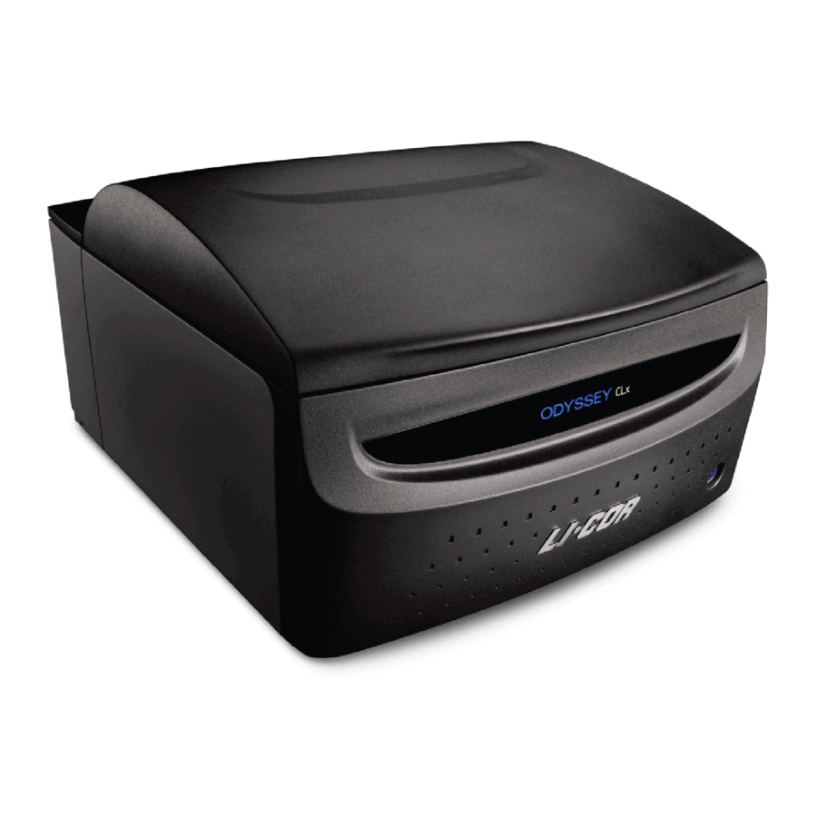
External Panels and Controls Front Panel and Scanning Surface Figure 4-1. Front panel features and power button on the Odyssey CLx. Power On/Off Button: Briefly pressing this button turns the instrument on and off, when the instrument is not connected to the Image Studio™ Software. If the instrument is connected, pressing the button results in the red error light blinking along with a warning sound to alert the user that the instrument is connected to the software. -
Page 16: Rear Panel
Chapter 2: System Overview Figure 4-2. Location of the green image acquisition light and red error light. Red Error Indicator: The error indicator light illuminates when a particular process could not be completed. Rear Panel Power switch CDRH Power regulation receptacle compliance label Manufacturer... -
Page 17: Scanning Surface
First, exit the Image Studio Software by selecting Instrument > Disconnect on the Application menu or by closing the application window. Next, briefly press the power button on the front panel to power off the Odyssey CLx. Then remove the power cord from the power receptacle as described in Electrical Considerations on page 12. -
Page 18: Software Overview
The Odyssey® CLx Imager has two modes for dynamic range, Automatic and Manual. In Automatic mode the Odyssey CLx acquires images with virtually no saturated pixels on the first attempt with no user adjustments. More than six logs (22 bits) of dynamic range are available for each image. In Manual mode the intensity of each channel can be manually adjusted across a 12 bit dynamic range. -
Page 19: Chapter 3: Operation
The scanning surface is plate glass. It is very important that the scanning surface glass and silicone mat be free of smudges, dust, and dye before scanning any samples on the Odyssey CLx. Contaminated surfaces in contact with the membrane surface may cause blotches and streaks that cannot be removed with further washing. - Page 20 Chapter 3: Operation The following are general tips for handling membranes and imaging membranes with the Odyssey® CLx. Handling Near-Infrared Western Blot Membranes Important: Do not touch the membrane – handle only with clean forceps. Lift the membrane only by the corners. Fingerprints, even from a glove, will show clearly when imaged. Use clean containers to avoid cross-contamination and reduce background.
-
Page 21: Using Gels
Odyssey® CLx Imager Image Studio™ Software Settings for Scanning Membranes The following settings are recommendations that are expected to work for most circumstances. You may need to empirically determine the best settings for your assay and research needs. Setup group Select No Analysis in the Analysis Typelist. - Page 22 Chapter 3: Operation Scanning Gels 1) Thoroughly rinse the gel with destaining solution or water to remove dye particulates. 2) When placing the gel on the scanning surface, take care not to trap air bubbles underneath. (Sample-Side Up) Not drawn to scale 3) Adjust the focus offset for the gel thickness.
-
Page 23: Using Multiwell Plates
Different models of plate differ with regard to properties such as well depth and autofluorescence. Plate dimensions must be such that the distance from the Odyssey CLx scanning surface to the target detection area of the plate is 4.0 mm or less. - Page 24 Chapter 3: Operation 2. Place the multiwell plate on the scan surface and slide it into place so that it contacts both the front and left sides of the Plate Alignment Guide. The first well in the first row (A1) should be toward the back and left side of the Plate Alignment Guide as shown (Figure 5-2).
-
Page 25: Scanning Slides
Odyssey® CLx Imager Select a Focus Offset of 4.0 mm when using the Greiner plates specified above. If you plates other than those suggested, the optimal focus offset will have to be determined empirically. Scan Area group Select No Image from the list. -
Page 26: Obtaining Technical Support
Obtaining Technical Support To resolve a problem with your Odyssey® CLx, start by contacting LI-COR Technical Support at 800-645-4260 (U.S. only), or emailing biohelp@licor.com. Outside of the U.S., contact your local sales office or distributor. Be prepared to give the serial number of your instrument, which can be found on the manufacturer label on the rear panel of the instrument (Figure 3-1). -
Page 27: Finding Empiria Studio Software Log Files
Odyssey® CLx Imager 1) Click the Image Studio Application Button, point to Logs, and then click Export. The Zip Application Log Files dialog will open. 2) In the Zip Application Log Files dialog, select Most recent 2 Meg of log files and choose where to save the file. - Page 28 Page 28...
-
Page 29: Chapter 4: Appendix
Network Connection: Cat. 5e RJ45, 10BASE-T/100BASE-TX/1000BASE-T. Use only the supplied cable. Embedded Firmware Source Code The embedded firmware running on the Odyssey CLx Imager (model number 9140) utilizes open source software. To obtain source code or related information, contact LI-COR Support at http://www.licor.com/biotechsupport. - Page 30 Page 30...
Need help?
Do you have a question about the Odyssey CLx and is the answer not in the manual?
Questions and answers