Advertisement
Available languages
Available languages
Quick Links
JS PRODUCTS | 6445 MONTESSOURI STREET, LAS VEGAS, NV 89113
(NOV19)
Part No. 41631
Copyright © 2019 D
D
WALT
and the D
WALT Logo are trademarks of the D
®
E
E
and are used under license. The yellow/black color scheme is a trademark for D
power tools & accessories.
Definitions: Safety Guidelines
The definitions below describe the level of severity for each signal word. Please
read the manual and pay attention to these symbols.
WARNING: Indicates a potentially hazardous situation which, if not avoided, could
result in death or serious injury.
CAUTION: Indicates a potentially hazardous situation which, if not avoided, may
result in minor or moderate injury.
(Used without word) Indicates a safety related message.
NOTICE:
Indicates a practice not related to personal injury which, if not avoided,
may result in property damage.
IF YOU HAVE ANY QUESTIONS OR COMMENTS ABOUT THIS OR ANY D
CALL US TOLL FREE AT: 1-855-558-2422
WARNING! Read and understand all instructions.
important safety and operating instructions.
before assembling this storage rack and save it for reference.
SAVE THESE INSTRUCTIONS
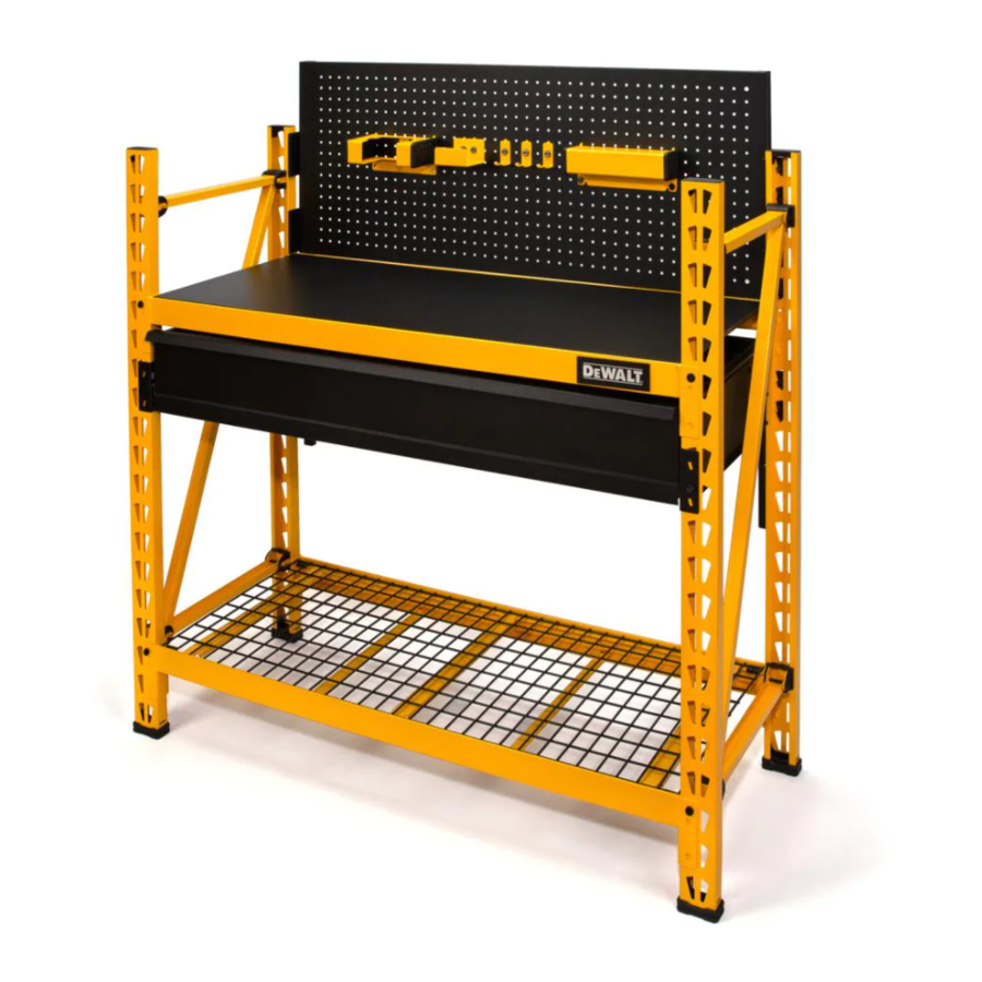
TECHNICAL SPECIFICATIONS
Technical Specifications
INDUSTRIAL RACK
Total Rack Capacity
Capacity per Shelf
WORK STATION
Height
Width
Depth
DRAWER KIT
Height
Width
Depth
Drawer Capacity
PEGBOARD
Height
Width
DXST3000WB
Copyright © 2019, D
WALT
E
WALT.
E
WALT Industrial Tool Co., or an affliate thereof
E
WALT TOOL,
E
This manual contains
Please read this manual carefully
3,000 lbs. (1,360.78 kg)
*when weight is evenly distributed
1,500 lbs. (680 kg)
*when weight is evenly distributed
47"
(119.4 cm)
49.5"
(125.73 cm)
18"
(45.72 cm)
6.21"
(15.77 cm)
42.95"
(109.09 cm)
16.86"
(42.82 cm)
120 lbs. (54.43 kg)
18"
(45.72 cm)
47"
(119.4 cm)
GENERAL SAFETY
• Keep work area clean and dry.
• Use correct/recommended tools for the job.
• Never leave unattended tools plugged in or running.
• Never force a part into place.
• Wear appropriate safety apparel for the job you are doing.
• Wear safety glasses/goggles.
• Never crawl, sit, stand, or climb on the rack, pegboards, or drawer.
• Never overload the Drawer Kit.
• Do not leave drawer open.
• Keep small parts away from children. Never leave a small child unattended while assembling.
• Always use common sense – your personal safety is your responsibility.
SPECIFIC SAFETY FOR WALL MOUNT BRACKET
WARNING:
Serious injury or death can occur from the rack tipping over. To prevent this, the rack
must be secured to a wall, especially in earthquake -prone areas, or where surfaces are uneven, and where
children and/or pets are present.
Different wall materials require different types of fasteners. Use fasteners suitable for your specific type of
wall. If you are uncertain about what type of fastener to use, then please contact your local hardware store.
WARNING:
• Maximum load for the Drawer: Up to 120 lbs. (54.43 kg) when evenly distributed.
• Maximum load for each shelf: Up to 1,500 lbs. (680 kg) when weight is evenly distributed.
• It is recommended that the heaviest load be placed on the bottom shelf.
• Immediately remove the load should there be damage, bending or warping of the rack uprights
Parts List
No. Description
1
Vertical Beam
2
Pre-Bolted Vertical Assembly
3
Vertical Assembly Bolt
4
Crossbeam
5
Shelf Support Strap
6
Safety Strap With Weld Nut
7
Safety Strap Bolt
8
Laminate Deck
9
Wire Grid
10
Locking Pin
11
Carriage Bolt
12
10 mm Nut
13
10 mm Wrench
14
4 mm Hex Key
15
4 mm Hex Bit
16
Wall Mount Bracket Assembly
WALT
E
17
Stacking Plate
1
10
11
12
13
17
18
19
22
NEVER EXCEED THE FOLLOWING WEIGHT LIMITS
Qty.
No. Description
2
18
Locking Grid Clip
2
19
U-Bracket Cover
4
20
Fold Up Drawer
4
21
Drawer Pull
6
Mounting Bracket with
22
Drawer Slides
4
8
23
Drawer Carriage Bolts
1
24
Drawer Carriage Nut
1
25
Metal Pegboard
29
26
Pegboard Mounting Beam
2
27
Side Mounting Bracket (Right)
2
28
Side Mounting Bracket (Left)
1
29
Rear Mounting Bracket (Right)
1
30
Rear Mounting Bracket (Left)
1
31
Small Locking Pin
1
32
Pegboard Tool Holders
2
3
2
4
5
6
7
8
9
14
15
20
21
23
24
Qty.
4
4
1
1
2
4
4
1
2
2
2
2
2
8
6
16
Advertisement

Related Manuals for DeWalt DXST3000WB


Summary of Contents for DeWalt DXST3000WB
- Page 1 Rear Mounting Bracket (Right) JS PRODUCTS | 6445 MONTESSOURI STREET, LAS VEGAS, NV 89113 4 mm Hex Key Rear Mounting Bracket (Left) (NOV19) Part No. 41631 DXST3000WB Copyright © 2019, D WALT 4 mm Hex Bit Small Locking Pin Copyright © 2019 D WALT.
-
Page 2: Before You Begin
Crossbeam Installation (Fig. 3-5) NOTE: It is recommended for one person to hold the upright frames in place while a second person installs the crossbeams. 1. There is a set of locking tabs at both ends of every crossbeam. To begin assembly, take one crossbeam and insert the tabs into two of the holes on the lower portion of one upright frame. - Page 3 WALT WALT et le logo D WALT sont des marques de commerce de DEWALT Industrial Tool Co. ou d’une ® NOTE: Having a helper will ease the assembly of the pegboard while lining up the mounting tabs. société affiliée à cette dernière et sont utilisés sous licence. L’agencement de couleurs jaune et noir est une NOTE: The (2) pegboard mounting beams will be used to elevate the pegboard above the shelf to effectively marque de commerce des outlils électriques et accessorires D...
-
Page 4: Mesures De Sécurité Générales
MESURES DE SÉCURITÉ GÉNÉRALES • Gardez la zone de travail propre et sèche. • Utilisez des outils appropriés/recommandés pour le travail. • Ne laissez jamais les outils sans surveillance. • Ne forcez jamais une pièce. • Portez des vêtements de sécurité. •... - Page 5 Instructions pour la traverse (Fig. 3-5) 3. Une fois installée, la fixation en U peut être déplacée d’un côté à l’autre (entre les deux barres de sécurité). Ceci permet de la fixer à une pièce de bois de deux pouces sur quatre pouces dans le mur. REMARQUE : Il est recommandé...
-
Page 6: Especificaciones Técnicas
JS PRODUCTS | 6445 MONTESSOURI STREET, LAS VEGAS, NV 89113 29 Soporte de montaje trasero (derecha) 13 Llave de 10 mm (NOV19) Part No. 41631 DXST3000WB Copyright © 2018, D WALT 30 Soporte de montaje trasero (izquierda) 14 Llave hexagonal 4 mm ... -
Page 7: Antes De Empezar
5. Repita los pasos 1 a 4 para ensamblar los tres marcos verticales restantes. Una vez que todos estén ensamblados, ajuste los pernos por completo en las cuatro esquinas. Tenga cuidado de no ajustar demasiado los pernos. No debe haber ninguna deformación en los soportes en forma de U ni en las vigas horizontales. - Page 8 3. Para cada conjunto de travesaños, coloque una agarradera de soporte de estante perpendicular a los FIG. 20 FIG. 21 FIG. 19 travesaños e inserte cada extremo en las ranuras a cada lado del travesaño. (Fig. 11) VIGA DE MONTAJE DE PANEL VIGA DE MONTAJE PANEL PERFORADO...