JRC JCY-1900 Service Manual
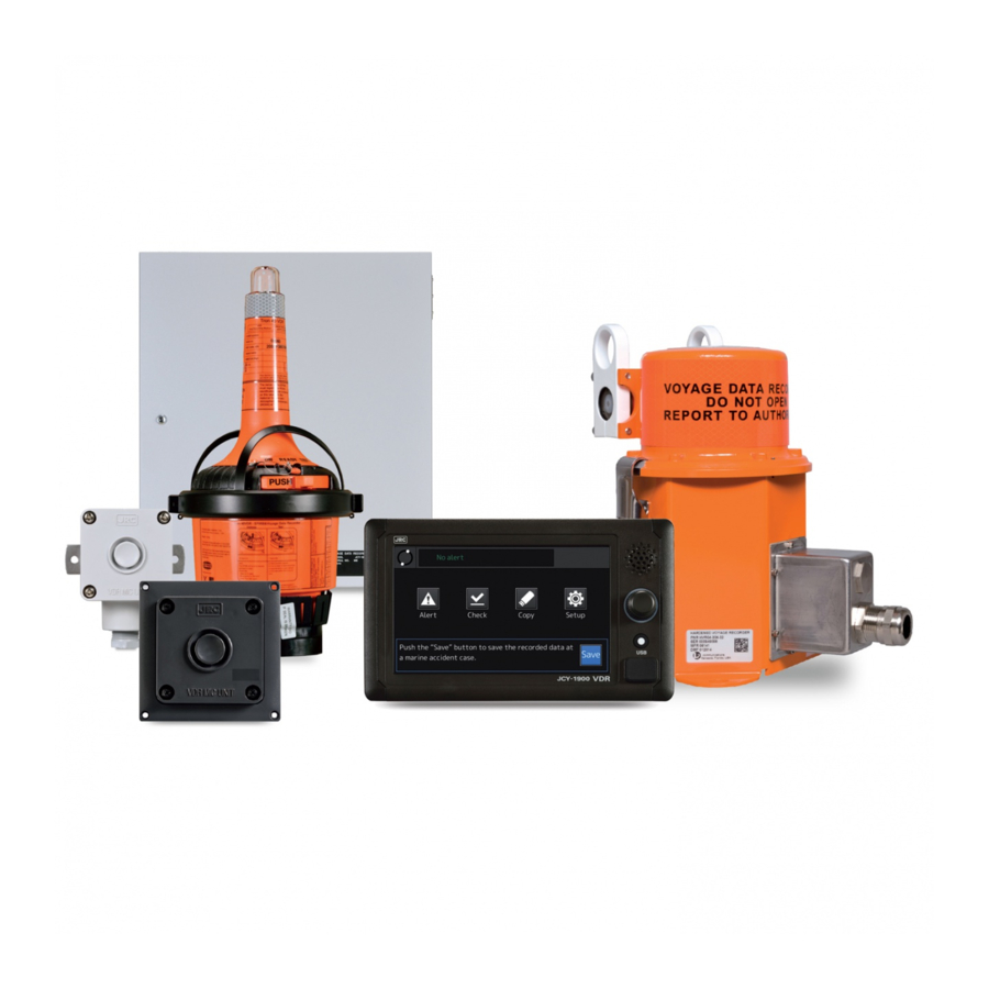
Voyage data recorder
Hide thumbs
Also See for JCY-1900:
- Instruction manual (174 pages) ,
- Operation manual (2 pages) ,
- Instruction manual (110 pages)

Related Manuals for JRC JCY-1900


Summary of Contents for JRC JCY-1900
- Page 1 JCY-1900/1950 JCY-1900/1950 VOYAGE DATA RECORDER ( VDR VDR ) VOYAGE DATA RECORDER SIMPLIFIED VOYAGE DATA RECORDER ( S - VDR VDR ) SIMPLIFIED VOYAGE DATA RECORDER SERVICE MANUAL SERVICE MANUAL...
- Page 3 NOTICE It is strictly prohibited to reproduce part or all of this manual without prior permission. The contents of this manual are subject to change without notice. Copyright© Japan Radio Co., Ltd. 2014 All rights reserved. 7ZPNA4409...
- Page 5 JCY-1900/1950 VDR Service Manual DOC No. 7ZPNA4409...
-
Page 6: Before Operation
JCY-1900/1950 VDR Service Manual Before Operation Pictorial indication Various pictorial indications are included in this manual and are shown on this equipment so that you can operate them safely and correctly and prevent any danger to you and / or to other persons and any damage to your property during operation. - Page 7 JCY-1900/1950 VDR Service Manual DOC No. 7ZPNA4409...
-
Page 8: Precautions
JCY-1900/1950 VDR Service Manual Precautions DANGER The prohibited matter of a battery and a lithium battery. ● To short-circuit the + pin and – pin. ● Using for non-specified applications. ● disassembling, modifying, destroying. ● Throwing into fire, heating. ● Using expired battery. - Page 9 JCY-1900/1950 VDR Service Manual WARNING If equipment malfunctions, make sure to turn off the main power, open the breaker, and please contact our head office, or a nearby branch or local office to request servicing. The continuous use of the equipment may cause a fire or electric shock.
- Page 10 JCY-1900/1950 VDR Service Manual WARNING The Recording Control Unit (NDV-1900/1950) has a UTILITY OUTLET. When you connect the power plug to the power outlet, insert it firmly. Failure to do so may cause fire, burns or electric shock. The Recording Control Unit (NDV-1900/1950) has a UTILITY OUTLET.
- Page 11 JCY-1900/1950 VDR Service Manual CAUTION This equipment has warning labels. Do not try to remove, break or modify the label. Do not install the equipment on the location where infringed by water, humidity, steam, dust, or soot. Otherwise, it may cause a fire, electric shock, or malfunction.
- Page 12 JCY-1900/1950 VDR Service Manual CAUTION Do not block up the air vent of this equipment. Otherwise, the inside of equipment is filled with heat, and it may cause fire or malfunction. Do not install the equipment on the unstable place such as on the shaky stand or inclined surface.
-
Page 13: Precautions (Ffc)
JCY-1900/1950 VDR Service Manual Precautions (FFC) WARNING If the false distress alert is transmitted, take the following instructions immediately. (1) Stop the transmission immediately. (2) Report the following information to the Maritime Safety Agency. (a) Ship’s Name, Type and Flag... - Page 14 ID are wrong. If the ship's name and ID indicated on the label of the capsule unit is wrong, ask the purchasing dealer, JRC agent or the JRC branches to change it with correct ship's name and ID.
- Page 15 When sell the ship, contact to the purchasing dealer, JRC agent or JRC branches, and request to register the radio station license and reset up the ship's name and ID.
- Page 16 If the abnormal status is recognized in the capsule. request the service to purchasing dealer, JRC agent or JRC branches, If you want to replace or repair the capsule, contact the purchasing dealer, JRC agent or JRC branches. Do not use a solvent (paint-thinner, alcohol etc.) or alkaline/neutral detergent to clean up the capsule.
-
Page 17: Table Of Contents
JCY-1900/1950 Configuration ........................3 1.4. Present and New Model Comparison Table ..................... 8 1.5. JCY-1900/1950 System Diagram ......................10 1.6. JCY-1900/1950 System Block Diagram ....................11 1.7. JCY-1900/1950 System Network Diagram ....................14 1.8. JCY-1900/1950 System Configuration ....................15 MAINTENANCE ..........................26 2.1. - Page 18 JCY-1900/1950 VDR Service Manual 7.12. General Environmental Condition ......................94 ANNUAL INSPECTION ......................... 96 8.1. Declaration on Completion of Annual Inspection for VDR ..............96 8.2. Annual Inspection Procedures ....................... 96 INSPECTION CHECK LIST FOR VDR ..................96 DOC No. 7ZPNA4409...
-
Page 19: Outline
Both the fixed protective capsule unit and the float-free capsule unit store the data recorded for the past 48 hours. ● In VDR (JCY-1900), install both the protective and the float-free. In S-VDR (JCY-1950), install one of capsules. ● When retrieving the capsule units from the sea, with this 48-hour data recording function, the situation in the event of an accident can be analyzed by comparing it to that before the accident. - Page 20 1. OUTLINE JCY-1900/1950 VDR Service Manual Standards: • The 3 screens (X band RADAR, S band RADAR and ECDIS) are recorded every 15 seconds. * When Rader is standby, the screen is recorded every 20 minutes. (The requirement by the standard is recording every 10 to 30 minutes.)
-
Page 21: Jcy-1900/1950 Configuration
1. OUTLINE JCY-1900/1950 VDR Service Manual 1.3. JCY-1900/1950 Configuration 1.3.1. JCY-1900 Configuration 1) Standard configuration of the equipment Component Name Type Name Function Recording Control NDV-1900 - Output the recorded data to the fixed pro- Unit (RCU) tective capsule unit, the float-free capsule unit. - Page 22 1. OUTLINE JCY-1900/1950 VDR Service Manual 2) Options configuration of the equipment Component Name Type Name Function Microphone unit NVT-181 Excluding the 4 units of standard configura- tion, the microphone can install 8 units of Waterproof microphone unit NVT-182 option units.
- Page 23 1. OUTLINE JCY-1900/1950 VDR Service Manual 1.3.2. JCY-1950 Configuration 1) Standard configuration of the equipment • Fixed Protective Capsule Unit Component Name Type Name Function Recording Control NDV-1950 - Output the recorded data to the fixed pro- Unit (RCU) tective capsule unit, the float-free capsule unit.
- Page 24 1. OUTLINE JCY-1900/1950 VDR Service Manual • Float-free Capsule Unit Component Name Type Name Function Recording Control NDV-1950 - Output the recorded data to the fixed pro- Unit (RCU) tective capsule unit, the float-free capsule unit. Main Control CDJ-2510 - Recording data to the internal storage.
- Page 25 1. OUTLINE JCY-1900/1950 VDR Service Manual 2) Options configuration of the equipment Component Name Type Name Function Microphone unit NVT-181 Excluding the 4 units of standard configura- tion, the microphone can install 8 units of Waterproof microphone unit NVT-182 option units.
-
Page 26: Present And New Model Comparison Table
1. OUTLINE JCY-1900/1950 VDR Service Manual 1.4. Present and New Model Comparison Table * In S-VDR, use one of capsules (: NDH-338 or NDH-339). 1) Standard specifications Item JCY-1900/1950 JCY-1800/1850 Capsule Fixed Protective Capsule Unit Protective Capsule Unit ・48 hours recording ・12 hours recording... - Page 27 ・Recorded data of 12 hours worth can be taken within 2.5 hours. Playback Playback software is attached. Same as JCY-1900 * The under lined parts in JCY-1900 column meet the demands of the new specifications. 2) Option specifications Item JCY-1900/1950 JCY-1800/1850...
-
Page 28: Jcy-1900/1950 System Diagram
1. OUTLINE JCY-1900/1950 VDR Service Manual 1.5. JCY-1900/1950 System Diagram * In S-VDR, use one of capsules (: NDH-338 or NDH-339). * In S-VDR(JCY-1950), the following type name is changed. ・Recording Control Unit(RCU): NDV-1950 ・Operation Panel Unit(OPU): NCG-1950 DOC No. 7ZPNA4409... -
Page 29: Jcy-1900/1950 System Block Diagram
1. OUTLINE JCY-1900/1950 VDR Service Manual 1.6. JCY-1900/1950 System Block Diagram 1.6.1. JCY-1900 System Block Diagram ■Connecting MFD/RADAR/ECDIS via IEC61162-450(Ethernet) DOC No. 7ZPNA4409... - Page 30 1. OUTLINE JCY-1900/1950 VDR Service Manual ■Connecting RADAR/ECDIS and optional Frame Grabber Unit (NWP-69) via RGB signal DOC No. 7ZPNA4409...
- Page 31 JCY-1900/1950 VDR Service Manual 1.6.2. JCY-1950 System Block Diagram In S-VDR(JCY-1950), Connection of the capsule to the RCU is different from the VDR(JCY-1900). According to the following figure, replace chapter 1.6.1. (JCY-1900) with the figure of JCY-1950. * In S-VDR(JCY-1950), the following type name is changed.
-
Page 32: Jcy-1900/1950 System Network Diagram
1. OUTLINE JCY-1900/1950 VDR Service Manual 1.7. JCY-1900/1950 System Network Diagram * In S-VDR(JCY-1950), use one of capsules (: NDH-338 and NDH-339). * In S-VDR, the following type name is changed. ・Recording Control Unit(RCU): NDV-1950 ・Operation Panel Unit(OPU): NCG-1950 DOC No. 7ZPNA4409... -
Page 33: Jcy-1900/1950 System Configuration
1. OUTLINE JCY-1900/1950 VDR Service Manual 1.8. JCY-1900/1950 System Configuration * In S-VDR, use one of capsules (: NDH-338 or NDH-339). System Configuration Unit Type Name Circuitry Model number Remarks Recording Control NDV-1900/1950 Main Control Board CDJ-2510 Unit (MCB) (RCU) - Page 34 1. OUTLINE JCY-1900/1950 VDR Service Manual Recording Control Unit RCU: NDV-1900/1950 Long-term medium (SSD) Main Control Board Audio Recording Board Power Supply Unit Terminal Board Battery DOC No. 7ZPNA4409...
- Page 35 1. OUTLINE JCY-1900/1950 VDR Service Manual Operation Panel Unit OPU: NCG-1900/1950 7-inch Touch Panel Speaker Rotary Knob HOME Button USB Port DOC No. 7ZPNA4409...
- Page 36 1. OUTLINE JCY-1900/1950 VDR Service Manual Fixed Protective Capsule Unit FPC: NDH-338 DOC No. 7ZPNA4409...
- Page 37 1. OUTLINE JCY-1900/1950 VDR Service Manual Float-free Capsule Unit FFC: NDH-339 UNIT : mm DOC No. 7ZPNA4409...
- Page 38 1. OUTLINE JCY-1900/1950 VDR Service Manual Junction Box: NQE-7700A UNIT : mm DOC No. 7ZPNA4409...
- Page 39 1. OUTLINE JCY-1900/1950 VDR Service Manual Microphone Unit: NVT-181 Plug hole Coated grommet Waterproof Microphone Unit: NVT-182 DOC No. 7ZPNA4409...
- Page 40 1. OUTLINE JCY-1900/1950 VDR Service Manual Frame Grabber Unit FGU: NWP-69 D-sub Connector LAN Connector Ground Terminal Power Switch Power Terminal Fuse Block Frame Grabber Board Filter Board DOC No. 7ZPNA4409...
- Page 41 1. OUTLINE JCY-1900/1950 VDR Service Manual Digital Signal Converter DSC: NCT-82 (32ch) UNIT : mm Dry Contact Signal Input Board Filter Board Power Supply Unit DOC No. 7ZPNA4409...
- Page 42 1. OUTLINE JCY-1900/1950 VDR Service Manual Digital Signal Converter DSC: NCT-83 (64ch) Power Supply Unit Dry Contact Signal Input Board Filter Board DOC No. 7ZPNA4409...
- Page 43 1. OUTLINE JCY-1900/1950 VDR Service Manual Data Acquisition Unit DAU: NCT-84 Analog Option Board Gyro I/F Board Serial LAN Converter Board Filter Board DOC No. 7ZPNA4409...
-
Page 44: Maintenance
2. MAINTENANCE JCY-1900/1950 VDR Service Manual MAINTENANCE 2.1. Replacement Parts list The following is replacement parts. Using the OPU, check the expiration date. (Refer to 3.4.3.) * When replacing parts, it is necessary to set the expiration date with maintenance software. (Refer to 2.9.2) -
Page 45: Maintenance Parts List
2. MAINTENANCE JCY-1900/1950 VDR Service Manual 2.2. Maintenance Parts list The following is maintenance parts. Unit (Model) Remark Parts name (Code) Main Control Board (CDJ2510) With two security seal. (NDV-1900/1950) Long-term recording medium (CDD756) 1 piece. Need two pieces in the system. -
Page 46: Spare Parts List
2. MAINTENANCE JCY-1900/1950 VDR Service Manual 2.3. Spare Parts list The following is spare parts that are attached to each unit. 1) Standard configuration of the equipment Name of Component Type Name Parts Spare Parts for RCU H-7ZXNA4015 fuse:FIH 250 (NDV-1900/1950) 5A(TP.CR)URCSQD-H00(5ZFWU00005) -
Page 47: Fixed Protective Capsule Unit : Ndh-338
2. MAINTENANCE JCY-1900/1950 VDR Service Manual 2.4. Fixed Protective Capsule Unit : NDH-338 2.4.1. Exchange of the beacon 1) The removal method Remove the bracket with Beacon from the cap- sule unit. 1) Remove four inner side hexagon screws and remove a bracket. -
Page 48: Recording Control Unit : Ndv-1900/1950
2. MAINTENANCE JCY-1900/1950 VDR Service Manual 2.5. Recording Control Unit : NDV-1900/1950 * Before removal, check that the power supply of the RCU is OFF. 2.5.1. Exchange of the Battery 1) The mounting method In the following steps, loosen four screws, and remove the bracket. - Page 49 2. MAINTENANCE JCY-1900/1950 VDR Service Manual Connect the connector of battery cable to the terminal. Terminal of PSU Fix the battery cable by twisting the Coaching clip. The procedure mounting a battery is completed. * Set the expiration date with maintenance software.
- Page 50 2. MAINTENANCE JCY-1900/1950 VDR Service Manual 2.5.2. Exchange of the fuse 1) Fuse in PSU FIH 250 5A(TP.CR)URCSQD-H00 (5ZFWU00005) 2) Fuse in battery MF60NR 250V 10 (5ZFGD00017) 3) Fuse in External Signal Connection I/F Board 1203 (5ZFCK00016) DOC No. 7ZPNA4409...
- Page 51 2. MAINTENANCE JCY-1900/1950 VDR Service Manual 2.5.3. Exchange of the Fan 1) The removal method Remove the PSU cover. 1) Remove the battery cable. 2) Remove four screws, remove the cover. Remove Fan cable. cable clamp J508 J507 1) Remove cable from J507 and J508 on the MCB.
- Page 52 2. MAINTENANCE JCY-1900/1950 VDR Service Manual Remove the Fan unit(Fan*2+Bracket). 1) Remove two screws in the front side. 2) Loosen a screw in the rear side. 3) Sliding the Bracket to the left, remove the unit. Remove the Fan from the Bracket.
- Page 53 2. MAINTENANCE JCY-1900/1950 VDR Service Manual 2) The mounting method Carry out mounting in the reverse order to removal. * When attaching the Fan to the Bracket, turn the label to the outside of the Bracket, and the cable to upper side.
- Page 54 2. MAINTENANCE JCY-1900/1950 VDR Service Manual 2.5.4. Exchange of the Audio Recording Board 1) The removal method Remove six screws, remove the protect cover. Remove two cable on the ARB. 1) Remove W105 from J604. 2) Remove W104 from J504.
- Page 55 2. MAINTENANCE JCY-1900/1950 VDR Service Manual 2) The mounting method Carry out mounting in the reverse order to removal.. * Insert the ARB in two connectors on the MCB firmly. * Be careful of routing of the cable W104, W105.
- Page 56 2. MAINTENANCE JCY-1900/1950 VDR Service Manual 2.5.5. Exchange of the Internal Storage (SSD) 1) The removal method Remove the protect cover and the ARB. Refer to 2.5.4. SSD#1 SSD#2 * Two SSD are connected to the MCB upper part. Remove the SSD.
- Page 57 2. MAINTENANCE JCY-1900/1950 VDR Service Manual 2) The mounting method Carry out mounting in the reverse order to removal.. * When connecting the SSD into J504(J505), adjust according to the four screw hole position. (When inserting the SSD into J504(J505) all the way, screw holes may not fit.)...
- Page 58 2. MAINTENANCE JCY-1900/1950 VDR Service Manual Remove the MCB. 1) Remove six hexagon spacers. * Use the nut driver. 2) Remove five screws. 2) The mounting method Carry out mounting in the reverse order to removal. * Connect the cable Z101(rear side Fan) to J507, Connect the cable Z102(front side Fan)to J508.
- Page 59 2. MAINTENANCE JCY-1900/1950 VDR Service Manual 2.5.7. Exchange of the Power Supply Unit 1) The removal method Remove the PSU cover. 1) Remove the battery cable. 2) Remove four screws in front, remove the cov- Remove two cable from the PSU.
- Page 60 2. MAINTENANCE JCY-1900/1950 VDR Service Manual 2) The mounting method Carry out mounting in the reverse order to removal. * Be careful of routing of cable W101, W102. W101 routing W102 routing DOC No. 7ZPNA4409...
-
Page 61: Digital Signal Converter 32Ch/64Ch: Nct-82/-83
2. MAINTENANCE JCY-1900/1950 VDR Service Manual 2.6. Digital Signal Converter 32CH/64CH: NCT-82/-83 2.6.1. Exchange of the Fuse Fuse: MF51NR 250V 3.15(5ZFGD00201) DOC No. 7ZPNA4409... -
Page 62: Frame Grabber Unit : Nwp-69
2. MAINTENANCE JCY-1900/1950 VDR Service Manual 2.7. Frame Grabber Unit : NWP-69 2.7.1. Exchange of the Fuse Fuse: MF51NR 250V 3.15 (5ZFGD00201) 2.7.2. Exchange of the Fan 1) The removal method Remove four screws, remove the top cover. Remove the Fan cable from J1. - Page 63 2. MAINTENANCE JCY-1900/1950 VDR Service Manual Remove the Fan unit (Fan + Bracket). 1) Loosen two screws. 2) Sliding the unit below, remove the unit. Remove the Fan from the Bracket. 1) Remove four screws. 2) Exchange for new Fan.
-
Page 64: Data Acquisition Unit: Nct-84
2. MAINTENANCE JCY-1900/1950 VDR Service Manual 2.8. Data Acquisition Unit: NCT-84 2.8.1. Exchange of the Fuse Fuse:1215 (5ZFCK00017) Fuse:1203 (5ZFCK00016) Fuse: MF51NR 250V 0.5 (5ZFGD00019) Fuse MF51NR 250V 3.15 (5ZFGD00201) DOC No. 7ZPNA4409... -
Page 65: Software Update
2. MAINTENANCE JCY-1900/1950 VDR Service Manual 2.9. Software Update 2.9.1. Software Update The MCB, ARB and OPU software can be updated. Refer to Installation Manual (Software Part) section 9 for more in- formation. 1) Log in to the maintenance software, and select [Software Update] ⇒ Tab[SOFTWARE UPDATE]. -
Page 66: Operation Checking On Hardware
3. OPERATION CHECKING ON HARDWARE JCY-1900/1950 VDR Service Manual OPERATION CHECKING ON HARDWARE 3.1. Fixed Protective Capsule Unit : NDH-338 3.1.1. Check of the beacon 1) Expiration date Check the expiration date written to the beacon. When the expiration date is less than one year, replace the beacon. - Page 67 3. OPERATION CHECKING ON HARDWARE JCY-1900/1950 VDR Service Manual 3) Checking the beacon operation Monitor an outputting acoustic signal from the beacon with the Beacon checker (7HMNA4001). • Turn on the beacon tester with turning a volume switch. • Short-circuit between terminals in order to operate the Beacon.
-
Page 68: Float Free Capsule Unit : Ndh-339
3. OPERATION CHECKING ON HARDWARE JCY-1900/1950 VDR Service Manual 3.2. Float Free Capsule Unit : NDH-339 It recommends testing the following every month. 3.2.1. EPIRB function test There are two different kinds of tests that can be performed: “NORMAL SELF-TEST” and “EXTENDED SELF-TEST INCLUDING GPS-TEST”. - Page 69 3. OPERATION CHECKING ON HARDWARE JCY-1900/1950 VDR Service Manual ・Test passed after one single flash only. See the following table about error. Number of flashes Fault indication: NONE Low power on 406 MHz transmitter Low battery voltage Low power on 121.5 MHz transmitter PLL on 406 MHz transmitter out of lock PLL on 121.5 MHz transmitter out of lock...
- Page 70 3. OPERATION CHECKING ON HARDWARE JCY-1900/1950 VDR Service Manual 3.2.3. Check the expiration dates Check the following. If the expiry date is approaching, replace new one. ・ EPIRB Battery ・ Hydrostatic Release Unit (HRU) Expiration date of HRU (Hydrostatic Release Unit)...
-
Page 71: Recording Control Unit: Ndv-1900/1950
3. OPERATION CHECKING ON HARDWARE JCY-1900/1950 VDR Service Manual 3.3. Recording Control Unit: NDV-1900/1950 3.3.1. Main Control Board : CDJ-2510 LEDs are incorporated into every LAN connector in RCU to display the status. The lighting specifications of the LEDs LED Name... - Page 72 3. OPERATION CHECKING ON HARDWARE JCY-1900/1950 VDR Service Manual System status The MCB has LEDs that display RCU system status. The lighting specifications of the LEDs LED Name Lighting Specifications “SYS”(Green/Red) Lights green when RCU is operating. Blinks green when RCU startup.
- Page 73 3. OPERATION CHECKING ON HARDWARE JCY-1900/1950 VDR Service Manual 3.3.2. Audio Recording Board : CHA-1900 Audio Recording Board(CHA-1900) on the RCU has the LEDs that display the following state. Power The lighting specifications of the LEDs LED Name Lighting Specifications “POWER”(Green)...
- Page 74 3. OPERATION CHECKING ON HARDWARE JCY-1900/1950 VDR Service Manual RX LEDs DOC No. 7ZPNA4409...
- Page 75 3. OPERATION CHECKING ON HARDWARE JCY-1900/1950 VDR Service Manual 3.3.3. Battery 1) Expiration date Check the expiration date written to the battery. 2) Battery voltage To check the power supply battery voltage, use the maintenance software, or measure it at the following battery ter- minals with a digital volt-ohm meter.
- Page 76 3. OPERATION CHECKING ON HARDWARE JCY-1900/1950 VDR Service Manual 3.3.4. Fan Check that the Fan is rotating according to the following. 1) Check that the wind has come out from the air vent of the RCU right-hand side. 2) Check that no Fan alert is displayed on the OPU.
-
Page 77: Operation Panel Unit: Ncg-1900/1950
3. OPERATION CHECKING ON HARDWARE JCY-1900/1950 VDR Service Manual 3.4. Operation Panel Unit: NCG-1900/1950 3.4.1. Adjusting the screen brightness Touch [Setup]→[Dimmer] to call the Dimmer screen. Adjust the screen brightness by [up/down] button. Refer to Instruction Manual 4.6.2 for more information. - Page 78 3. OPERATION CHECKING ON HARDWARE JCY-1900/1950 VDR Service Manual 3.4.3. Check of expiration date in Replacement Parts Check expiration date of the Replacement parts. (Refer to 2.1). Touch [Setup]→[Replacement parts] to call the Replacement Parts screen. Refer to Instruction Manual for more information.
-
Page 79: Microphone Unit: Nvt-181 And Waterproof Microphone Unit: Nvt-182
3. OPERATION CHECKING ON HARDWARE JCY-1900/1950 VDR Service Manual 3.5. Microphone Unit: NVT-181 and Waterproof Microphone Unit: NVT-182 Touch [Check]→[Audio]→<an audio column > to call Audio data check screen. Check the recording and playback func- tion by [REC/PLAY] button. And Check MIC test by [Test] button. -
Page 80: Digital Signal Converter 32Ch And 64Ch : Nct-82/83
3. OPERATION CHECKING ON HARDWARE JCY-1900/1950 VDR Service Manual 3.6. Digital Signal Converter 32CH and 64CH : NCT-82/83 The dry Contact Signal Input Board (CQD-2284, 2285) on the DSC has the LEDs that display the following state. COMMUNICATION The lighting specifications of the LEDs:... - Page 81 3. OPERATION CHECKING ON HARDWARE JCY-1900/1950 VDR Service Manual *CD1-32 NCT-82 CQD-2284 *CD1-64 NCT-83 CQD-2285 DOC No. 7ZPNA4409...
-
Page 82: Frame Grabber Unit: Nwp-69
3. OPERATION CHECKING ON HARDWARE JCY-1900/1950 VDR Service Manual 3.7. Frame Grabber Unit: NWP-69 LEDs are incorporated into every LAN connector in FGU to display the status. The lighting specifications of the LEDs: LED Name Lighting Specifications LINK/ACT LED Lights when the LINK is established (Yellow) Blinks at the time of receiving or sending data. -
Page 83: Data Acquisition Unit: Nct-84
3. OPERATION CHECKING ON HARDWARE JCY-1900/1950 VDR Service Manual 3.8. Data Acquisition Unit: NCT-84 Serial LAN Converter Board (CMH-2370) on the DAU has LEDs that display the following state. POWER The lighting specifications of the LEDs: LED Name Lighting Specifications [24V](Green) Lights when the DAU is supplied with power. -
Page 92: Diagnosis Of The Connection Equipment By Remote Maintenance
5. DIAGNOSIS OF THE CONNECTION EQUIPMENT BY REMOTE MAINTENANCE JCY-1900/1950 VDR Service Manual DIAGNOSIS OF THE CONNECTION EQUIPMENT BY REMOTE MAINTENANCE Refer to Installation Manual (Software Part) section 7. DOC No. 7ZPNA4409... -
Page 93: Schematic Diagrams (Circuit Diagrams)
6. SCHEMATIC DIAGRAMS (CIRCUIT DIAGRAMS) JCY-1900/1950 VDR Service Manual SCHEMATIC DIAGRAMS (CIRCUIT DIAGRAMS) 6.1. Recording Control Unit: NDV-1900/1950 DOC No. 7ZPNA4409... -
Page 94: Operation Panel Unit: Ncg-1900/1950
6. SCHEMATIC DIAGRAMS (CIRCUIT DIAGRAMS) JCY-1900/1950 VDR Service Manual 6.2. Operation Panel Unit: NCG-1900/1950 DOC No. 7ZPNA4409... -
Page 95: Frame Grabber Unit: Nwp-69
6. SCHEMATIC DIAGRAMS (CIRCUIT DIAGRAMS) JCY-1900/1950 VDR Service Manual 6.3. Frame Grabber Unit: NWP-69 DOC No. 7ZPNA4409... -
Page 96: Digital Signal Converter 32Ch: Nct-82
6. SCHEMATIC DIAGRAMS (CIRCUIT DIAGRAMS) JCY-1900/1950 VDR Service Manual 6.4. Digital Signal Converter 32CH: NCT-82 P303 HIF3BA-30D-2.54DS J303 J301 P301 HIF3BA-30PA- B2P-VH(LF)(SN) VHR-2N 2.54DS(71) +5V 1 J302 DF1BZ-4P-2.5DS NC 1 NC 2 +5V 3 GND 4 TB302 TB301 1 CH0+... -
Page 97: Digital Signal Converter 64Ch: Nct-83
6. SCHEMATIC DIAGRAMS (CIRCUIT DIAGRAMS) JCY-1900/1950 VDR Service Manual 6.5. Digital Signal Converter 64CH: NCT-83 DOC No. 7ZPNA4409... -
Page 98: Data Acquisition Unit: Nct-84
6. SCHEMATIC DIAGRAMS (CIRCUIT DIAGRAMS) JCY-1900/1950 VDR Service Manual 6.6. Data Acquisition Unit: NCT-84 DOC No. 7ZPNA4409... -
Page 99: Specifications
7. SPECIFICATIONS JCY-1900/1950 VDR Service Manual 7. SPECIFICATIONS 7.1. NDH-338 Fixed Protective Capsule Unit Performance Interface Standard IEEE802.3 (10Base-T/ 100Base-TX) Protocol TCP/IP Recording duration and capacity Duration 48 hours Capacity 32GB Data recording interval Sensor data depends on the input from the sensors (usually 1 second) -
Page 100: Float Free Capsule Unit
7. SPECIFICATIONS JCY-1900/1950 VDR Service Manual 7.2. NDH-339 Float Free Capsule Unit Performance Interface Standard IEEE802.3 (10Base-T/ 100Base-TX) Protocol TCP/IP Recording duration and capacity Duration 48 hours Capacity 64GB Data Recording Interval Sensor data depends on the input from the sensors (usually 1 second) -
Page 101: Ndv-1900/1950 Recording Control Unit
7. SPECIFICATIONS JCY-1900/1950 VDR Service Manual 7.3. NDV-1900/1950 Recording Control Unit Performance Interface to the fixed protective capsule unit Standard IEEE802.3 (10Base-T/ 100Base-TX) Protocol TCP/IP Power supply Supply from the RCU Interface to the float-free capsule unit Standard IEEE802.3 (10Base-T/ 100Base-TX) - Page 102 7. SPECIFICATIONS JCY-1900/1950 VDR Service Manual Performance (continued) Image data input Standard IEC61162-450 Input channel up to 6 channel (image sources on the network) Recording interval 15 seconds per each image (X-Band Radar, S-Band Radar, Main-ECDIS and Sub-ECDIS) *Recording of each image is selected automatically.
- Page 103 7. SPECIFICATIONS JCY-1900/1950 VDR Service Manual Environmental condition Operating temperature -15 °C to +55 °C (IEC 60945 protected type) Temperature and humidity +40 °C, 93% (non condensing) Vibration 2Hz to 13.2Hz ±1.0mm 13.2Hz to 100Hz 0.7G Protection class IP22 General specification Power voltage AC100 - 120V ±10%, 1-phase 50/60Hz (IEC 60945)
-
Page 104: Ncg-1900/1950 Operation Panel Unit
7. SPECIFICATIONS JCY-1900/1950 VDR Service Manual 7.4. NCG-1900/1950 Operation Panel Unit Performance Mounting Flush mount type Interface to the RCU Standard IEEE802.3 (10Base-T/ 100Base-TX) Protocol TCP/IP Power supply Supply from the RCU Indication 7 inch wide color LCD (800 x 480 pixels),... -
Page 105: Microphone Unit
7. SPECIFICATIONS JCY-1900/1950 VDR Service Manual 7.5. NVT-181 Microphone Unit Performance Mounting Ceiling mount type Device Electoret condenser microphone Directivity Hemisphere indirectivity Range of Receive Radius of 3.5m Power supply Supply from the RCU Microphone test Built-in speaker for self-diagnosis test... -
Page 106: Waterproof Microphone Unit
7. SPECIFICATIONS JCY-1900/1950 VDR Service Manual 7.6. NVT-182 Waterproof Microphone Unit Performance Mounting Wall mount type Device Electoret condenser microphone Directivity Hemisphere indirectivity Range of Receive Radius of 3.5m Power supply Supply from the RCU Microphone test Built-in speaker for self-diagnosis test... -
Page 107: Digital Signal Converter 64Ch
7. SPECIFICATIONS JCY-1900/1950 VDR Service Manual 7.7. NCT-83 Digital Signal Converter 64CH Performance Dry contact input Dry contact Dry contact input channel Up to 64 channels Contact closure interface Driving power supply DC +12V logic Normal Close / Normal open... -
Page 108: Digital Signal Converter 32Ch
7. SPECIFICATIONS JCY-1900/1950 VDR Service Manual 7.8. NCT-82 Digital Signal Converter 32CH Performance Dry contact input Dry contact Dry contact input channel Up to 32 channels Contact closure interface Driving power supply DC +12V logic Normal Close / Normal open... -
Page 109: Frame Grabber Unit
7. SPECIFICATIONS JCY-1900/1950 VDR Service Manual 7.9. NWP-69 Frame Grabber Unit Performance Image data input Input channel 2 channels Input interface analog RGB/Hs/Vs - RGB 0.7Vp-p (video signal) - Hs - Vs Resolution 640 x 350 to 1600 x 1200 pixel (according to VESA DMTS) -
Page 110: Data Acquisition Unit
7. SPECIFICATIONS JCY-1900/1950 VDR Service Manual 7.10. NCT-84 Data Acquisition Unit Performance Input sensor channel IEC61162-1 8 channels IEC61162-2 2 channels Interface to the RCU Standard IEEE802.3 (10Base-T/ 100Base-TX) Protocol TCP/IP Compass safety distance Standard 0.9m Steering 0.5m Gyro interface... -
Page 111: Nqe-7700A Junction Box
7. SPECIFICATIONS JCY-1900/1950 VDR Service Manual 7.11. NQE-7700A Junction Box Performance interface Built-in terminal blocks Environmental condition Operating temperature: -25 °C to +55 °C (IEC 60945 protected type) Temperature and humidity: +40 °C, 93% (non condensing) Vibration: 2Hz to 13.2Hz ±1.0mm 13.2Hz to 100Hz 0.7G... -
Page 112: General Environmental Condition
7. SPECIFICATIONS JCY-1900/1950 VDR Service Manual 7.12. General Environmental Condition Operating condition and location Usage Conditions Target vessels - Mercantile vessels of 3000G/T or more that are engaged in inter- national voyage - Passenger vessels of 150G/T or more that are engaged in interna-... - Page 113 7. SPECIFICATIONS JCY-1900/1950 VDR Service Manual Environment condition Exposed type equipment Fixed Protective Capsule Unit, Waterproof Microphone Unit Operation temperature range -25 °C to +55 °C Storage temperature -25 °C to +70 °C Temperature and humidity +40 °C, 93% (non condensing) Vibration 2Hz to 13.2Hz ±1.0mm...
-
Page 114: Annual Inspection
INSPECTION CHEC LIST FOR VDR 8. ANNUAL INSPECTION 8.1. Declaration on Completion of Annual Inspection for VDR It's being adjusted 8.2. Annual Inspection Procedures It's being adjusted 9. INSPECTION CHECK LIST FOR VDR It's being adjusted... - Page 116 For further information,contact: Not use the asbestos http://www.jrc.co.jp Marine Service Department Telephone : +81-3-3492-1305 Facsimile : +81-3-3779-1420 e-mail : tmsc@jrc.co.jp AMSTERDAM Branch Telephone : +31-20-658-0750 Facsimile : +31-20-658-0755 e-mail : service@jrceurope.com SEATTLE Branch Telephone : +1-206-654-5644 Facsimile : +1-206-654-7030 e-mail : marineservice@jrcamerica.com...
Need help?
Do you have a question about the JCY-1900 and is the answer not in the manual?
Questions and answers