Table of Contents
Advertisement
Advertisement
Table of Contents

Related Manuals for Elstat EMS-55


Summary of Contents for Elstat EMS-55
-
Page 2: Table Of Contents
INDEX Contents Page General description of the EMS Installation instructions Locating the appliance and condenser sensors Self learning module Relearning and resets Soft start Minimum compressor rest time 11-12 Automatic defrost management Voltage management 12-13 Managing the internal fans Door open alarm Diagnostics Uninterrupted pull down function Button commands... -
Page 3: General Description Of The Ems
EMS-55-(R) Instruction Manual GENERAL DESCRIPTION The EMS (Energy Management System) saves energy by allowing the temperature in the cooler to rise during periods when the outlet is closed. The unit is totally self managing and does not require any interference of the user. It can substantially reduce the number of service calls whilst saving on average 38% energy. -
Page 4: Installation Instructions
INSTALLATION INSTRUCTIONS The EMS can be mounted either horizontally or vertically however, it is necessary when installing the EMS or RMD55 to ensure that the motion detection window has a clear and unrestricted view into the area in front of the cabinet. CONNECTIONS All line voltage connections are made via 6.5 mm spade terminals and all low voltage connections are made via screw terminal blocks. - Page 5 WIRING DIAGRAM In addition to the above wiring diagram, a door switch should also be wired into the system. This connection must go directly from the door switch to the terminals on the EMS (see printed label on the control housing). If a door switch is not used (not recommended) then a wire loop must be fitted to the door switch terminals on the EMS (see below).
-
Page 6: Locating The Appliance And Condenser Sensors
LOCATING THE APPLIANCE SENSOR IN THE RETURN AIR The most reliable and most accurate representation of the liquid temperature inside the appliance is the return air temperature. The air coming from the evaporator is, in the average cooler, between approximately -8 / -12 C. - Page 7 To ensure more accurate sensing of the discharge line temperature it is advisable to cover both sensor and discharge line with an insulation material. THE FASCIA MEMBRANE The membrane cannot be removed from the control fascia, if attempted to do so, the membrane will be permanently damaged and cannot be re-used.
-
Page 8: Self Learning Module
THE SELF LEARNING MODULE The EMS is capable of learning the opening and closing times of the outlet where the appliance is located. During opening hours the control will switch the appliance to operational mode and during closing times the control will automatically switch the appliance to stand-by mode. To achieve this each day is divided into 48 thirty minute periods and each period is represented by a single location in the EMS memory. - Page 9 For the detector to function correctly it must not be placed behind glass. The EMS55 has a motion detector integrated into the fascia of the control and the EMS-55-R has a connection for an external detector (RMD-55).
-
Page 10: Relearning And Resets
RE-LEARNING If the outlet’s business times change or the learnt pattern is incorrect then the EMS will automatically relearn. Under these circumstances the original pattern will be erased and the learning process will begin again from day 1. Please note that the activity frequency will not be recalculated during a relearn. -
Page 11: Soft Start
Disconnect the power to the control (unplug the cooler), push and hold the set and defrost buttons and restore the power. Keep the buttons pressed until the display shows the temperature again, release the buttons and the reset will be complete. (During this procedure there will be a short period when the display is blank). -
Page 12: Automatic Defrost Management
“SLO” (supply low) Please note that the EMS-55 does NOT rectify the voltage but merely monitors it and switches the refrigeration system on and off if the supply voltage falls below or rises above, the limits programmed in parameters HI and LO. -
Page 13: Managing The Internal Fans
220V – 240V Line voltage LO parameter value Line Voltage HI parameter value Line Voltage 173V 230V 178V 235V 182V 240V 187V 245V 192V 250V 197V 255V 203V 260V 265V 100V Line voltage (Japan) Line voltage LO parameter value Line Voltage HI parameter value 104V 110V... -
Page 14: Diagnostics
The EMS monitors the door status by means of the door switch. If the cooler door is left open for the period set in parameter AD, then an internal buzzer will sound to attract attention. To avoid irritation caused by this alarm, the buzzer will sound for the length of time set in parameter B1. If the door is still open after the buzzer has sounded then the EMS will close down the refrigeration system and will not restart it until the door is finally closed. -
Page 15: Button Commands
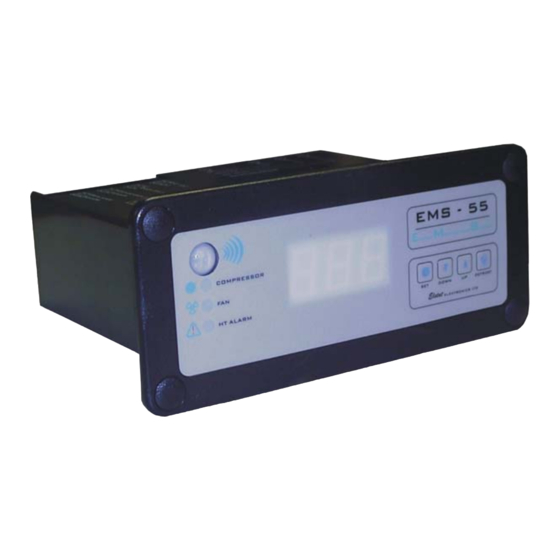
BUTTON COMMANDS AND FASCIA LAY-OUT Motion detection sensor The motion detection sensor is fitted with a lens to enhance the detection range and angle. Compressor “on” indicator light This is a green LED that illuminates each time the compressor is running. Fan “on”... - Page 16 LED Display The EMS 3 digit LED display may show any of the following: During power up the display initially shows 8.8.8. followed by two codes. The first code (e.g. E46) indicates the firmware version programmed into the control. The second code indicates the default parameter version (e.g.
- Page 17 Refrigeration system failure on the display indicates that the set point has not been reached during the time period set in parameter Ct. Supply Low. The line voltage has dropped to a level that may cause damage to the compressor. The EMS will not restart the compressor until the voltage reaches a safe level again.
-
Page 18: Control Settings
THE CONTROL SETTINGS The EMS has the following parameter values: EMS-55 Parameter Default Settings Parameter Description Degrees C Range Units Set Point See US & LS Upper Set Point 0-10 Lower Set Point 0-10 Differential 0.0-9.9 Calibration +/-9.9 Minimum Rest Time... - Page 19 Scroll through the parameter list until the desired parameter is shown. Then alter the value by pressing up or down button. Once the desired values are set allow the EMS to show the temperature again. EMS-55 PARAMETERS Parameter Description This parameter sets the compressor cut out temperature during operational mode.
- Page 20 Stand-by restart. To ensure that the product is at the correct temperature when the outlet opens, the EMS will switch to operational mode before hand. This parameter sets this period. Must be set to a multiple of 30. Refrigeration System Failure. This parameter sets the maximum continuous compressor run time without the set point being reached.
- Page 21 ACTIVATING A STATISTICS SCROLL To activate a statistics scroll press the UP and DOWN buttons simultaneously. During a statistics scroll the display firstly shows the statistic and then its reading. Each reading is displayed for approx. 20 seconds to enable the user to write the values down. After the control has completed the statistics scroll the display will automatically return to its standard duties.
- Page 22 Compressor cycles Compressor running hours Perishable mode (on/off) Statistic Reporting period Description Average 24 hours Continuously calculated from the highest and lowest registered temperature temperature. Lowest 24 hours The lowest temperature for the last 24-hour period. registered temperature Highest 24 hours The highest temperature for the last 24-hour period.
-
Page 23: Products In The Ems Range
THE PRODUCTS... -
Page 24: Display
TECHNICAL DATA Input voltage 12 Volt AC (from Elstat transformer) Maximum switch capacity per UL rating Compressor 16 A FLA, 96 A LRA 0.4 – 0.5 p.f. (120VAC/230VAC) Fan relay 4.4 A FLA Light relay 2.2 A FLA Maximum switch capacity per VDE rating Compressor 12 A , p.f. -
Page 25: Contact Information
For further information contact: Elstat Electronics Limited Unit C, Astra Business Centre Roman Way Preston Lancashire PR2 5AP United Kingdom Tel. +44 – 1772 – 703030 Fax +44 – 1772 – 703031 E-mail: technical.elstat@ukonline.co.uk sales@elstat.co.uk For North America, Canada and Mexico... -
Page 26: Statistical Scroll
SUPPLEMENT E43 AND E46 FIRMWARE DIFFERENCES Standard EMS firmware version has been updated from E43 to E46, for which the following changes have been made: 1. The display will show the cabinet temperature during operational mode rather than showing USE. 2.
Need help?
Do you have a question about the EMS-55 and is the answer not in the manual?
Questions and answers