Table of Contents
Advertisement
Advertisement
Table of Contents

Related Manuals for Micromeritics AccuPyc II 1340


Summary of Contents for Micromeritics AccuPyc II 1340
- Page 1 AccuPyc II 1340 Operator’s Manual V1.09 134-42801-01 Oct 2013...
- Page 2 © Micromeritics Instrument Corporation 2006-2013. All rights reserved. Printed in the U.S.A.
- Page 3 MICROMERITICS shall not be liable for consequential or other type damages resulting from the use of any of its products other than the liability stated above. This warranty is in lieu of all other warranties, express or implied, including, but not limited to, the implied warranties of merchantability or fitness for use.
-
Page 5: Table Of Contents
AccuPyc II 1340 Table of Contents TABLE OF CONTENTS 1. GENERAL INFORMATION Organization of the Manual ........... . . 1-1 Conventions . - Page 6 Table of Contents AccuPyc II 1340 Zero..............3-37 4.
- Page 7 AccuPyc II 1340 Table of Contents C. THEORY 10-, 100-, and 350-cm3 Units ........... C-1 1-cm3 and 2000-cm3 Units.
- Page 8 Table of Contents AccuPyc II 1340 Aug 2013...
-
Page 9: General Information
AccuPyc II 1340 Organization of the Manual 1. GENERAL INFORMATION This manual describes how to install, operate, and maintain the AccuPyc II 1340 Pycnometer. Organization of the Manual The manual is divided into sections as follows: Chapter 1 GENERAL INFORMATION Provides a general description and specifications of the pycnometer. - Page 10 Organization of the Manual AccuPyc II 1340 Appendix D TRANSMITTED DATA Provides the format for analysis and calibration data when transmitted to a serial printer. Appendix E MULTIPLE ANALYSIS MODULES Provides instructions on attaching multiple analysis modules. Appendix F TEMPERATURE-CONTROLLED ACCUPYC Provides instructions for attaching a bath circulator to the temperature- controlled AccuPyc.
-
Page 11: Conventions
AccuPyc II 1340 Organization of the Manual Conventions This manual uses the icons shown below to identify notes of importance, cautions, and warnings. Notes contain important information pertinent to the subject matter. Warnings contain information that help you prevent actions that may cause personal injury. -
Page 12: Equipment Description
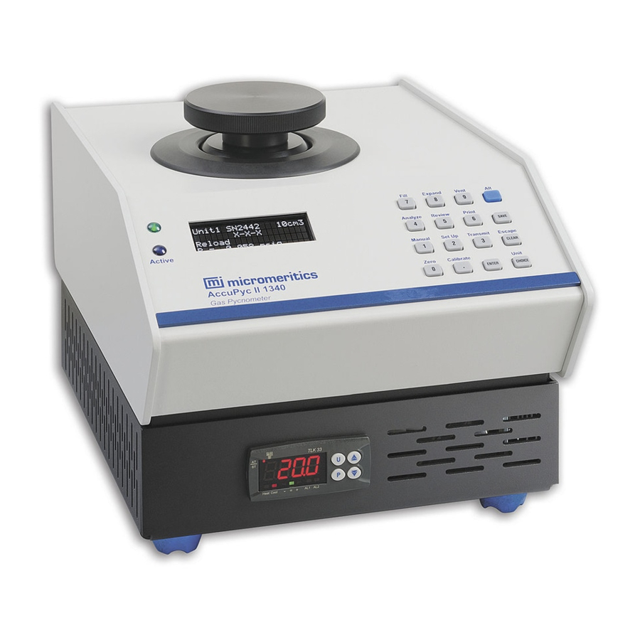
The AccuPyc II 1340 Pycnometer consists of a control module with a built-in keypad and display area, and an analysis module. When ordering a single unit, the analysis module is built into the same unit as the control module for convenience. -
Page 13: Configurations
AccuPyc II 1340 Equipment Description designated purge fill pressure. The chambers are then vented to atmosphere, resulting in elimination of water vapor or other contaminants. A cycle is used for collecting the precise, accurate data used in report calculations. Calibration is used to determine the size of the cell and expansion chambers within the instrument. -
Page 14: Options
Equipment Description AccuPyc II 1340 Glove Box A glove box unit for analysis of samples in which a controlled environment is required is available in the following configurations: • 1-cm sample chamber • 10-cm sample chamber • 100-cm sample chamber •... - Page 15 AccuPyc II 1340 Equipment Description Large-Volume Core Pycnometer The AccuPyc Large-Volume pycnometer sample chamber has been designed to address the specific needs of operations that require pore volume knowledge of intact drilling cores. This instrument elimi- nates the need to break core samples into smaller pieces prior to being analyzed.
-
Page 16: Specifications
Specifications AccuPyc II 1340 Specifications The AccuPyc II 1340 Pycnometer has been tested to meet the specifications in the following table. Characteristic Specification Environment Temperature: Stable between 15 and 35 ºC (59 to 96 ºF) Temperature-controlled AccuPyc: temperature stability is dependent upon specifications of the installed circulator. - Page 17 AccuPyc II 1340 Specifications Characteristic Specification (continued) Gases Research grade helium or nitrogen is recommended. If unavailable, use helium with a dew point of - 67 ºC (-88 ºF) or lower. Carbon dioxide, dry air, or argon can also be used for different applications.
- Page 18 Specifications AccuPyc II 1340 1-10 Aug 2013...
-
Page 19: Installation
Unpacking and Inspection Lifting the AccuPyc The AccuPyc II 1340 can be lifted by one person using two hands placed on opposite sides of the instrument. As always, proper lifting techniques should be used to prevent injury. Unpacking the Cartons When you receive the shipping cartons, carefully compare the Packing List with the equip- ment actually received and check the equipment for any damage during shipment. - Page 20 Make reference to the sales order or purchase order for the equipment, and provide the date the equipment was received. Notify a Micromeritics Service Representative of the defect and request shipping instructions. The Service Department will assign a Return Material Authorization (RMA) number to your return and provide shipping information.
-
Page 21: Installing The Analyzer
AccuPyc II 1340 Installing the Analyzer Installing the Analyzer The remainder of this chapter describes how to install the pycnometer and verify that it is operating properly. Location When selecting the location of the pycnometer, keep the following in mind: •... -
Page 22: Rear Panel Connections
Installing the Analyzer AccuPyc II 1340 Rear Panel Connections Multiple gases can be attached to the pycnometer using the Multigas option (refer to ORDERING INFORMATION, page Attach an appropriate regulator to the gas supply bottle or gas line, then tighten with a wrench. - Page 23 AccuPyc II 1340 Installing the Analyzer Purge the regulator and inlet tubing; this is important to prevent contamination of the analysis gas. a. Close the regulator shut-off valve; turn it fully clockwise. b. Turn the pressure regulator control knob fully counterclockwise.
- Page 24 Installing the Analyzer AccuPyc II 1340 Turn the nut on the tubing clockwise until it is finger-tight. Then use a 7/16-in. open- ended wrench (or an adjustable wrench) to tighten the nut an additional 1/4 turn. Open the shut-off valves for the gas bottle and the regulator.
- Page 25 AccuPyc II 1340 Installing the Analyzer If connecting a printer: a. Connect one end of the printer cable to a USB connector. Connect the other end to the input connector on the printer. b. Press to access the Set-up function c.
-
Page 26: Turning On And Off The Pycnometer
Installing the Analyzer AccuPyc II 1340 Turning On and Off the Pycnometer Place the power ON/OFF switch on the rear panel in the ON ( | ) position. After a few seconds, the system vents automatically and the green indicator light on the front panel illuminates. -
Page 27: Handling System Components
AccuPyc II 1340 Installing the Analyzer Handling System Components Listed in this section are guidelines for handling system components. Calibration Standard(s) These guidelines are for handling the calibration standard(s): • Wear latex or nitrile, powder-free gloves to prevent transfer of oil from your hands •... -
Page 28: Specifying System Options
Installing the Analyzer AccuPyc II 1340 Run your index finger around the O-ring groove. Replace the chamber cap; turn the cap clockwise to close it. Specifying System Options The pycnometer is shipped with system defaults as follows: Option Choices Default... -
Page 29: Calibrating The Pycnometer
AccuPyc II 1340 Installing the Analyzer Calibrating the Pycnometer Although calibrated before shipment, the pycnometer should be recalibrated to your laboratory atmospheric and environmental conditions. Calibration consists of a two-part procedure: • Specifying calibration parameters • Performing the calibration Specifying Calibration Parameters Calibration parameters are specified using the Analysis Parameters prompts. - Page 30 Installing the Analyzer AccuPyc II 1340 Press ENTER ; accept the default of 10 for the number of cycles. Unit[n] SN1234 10 cm3 Analysis Parameters Number of Cycles: Press ; accept the default cycle fill pressure of 19.500 psig. ENTER...
- Page 31 AccuPyc II 1340 Installing the Analyzer Performing the Calibration Wear rubber gloves whenever handling cups, standards, or inserts. Oil from your fingers may contaminate the surface and affect results. Turn the Pressure Control knob clockwise to set the regulator pressure at 21.500 psig (low-pressure gauge).
- Page 32 Installing the Analyzer AccuPyc II 1340 The first phase of the calibration, CAL1, calibrates the volume offset; status messages display until it is finished. The analyzer beeps three times at the end of this phase and displays the following prompt:...
-
Page 33: Verifying Operation
AccuPyc II 1340 Verifying Operation Verifying Operation This section provides instructions for performing an analysis on the calibration standard(s) to verify operation of your AccuPyc. You do not have to edit set-up values; the same values used in the calibration will be used in the analysis. -
Page 34: Installing Software Upgrades
Installing Software Upgrades AccuPyc II 1340 Installing Software Upgrades Place the On/Off switch on the rear panel in the Off ( O ) position. USB connectors On/Off switch Insert the USB media containing the software update into one of the USB connectors on the rear panel. -
Page 35: User Interface
AccuPyc II 1340 Controls, Indicators, and Connectors 3. USER INTERFACE This chapter contains information to familiarize you with the hardware and software of the AccuPyc. It is recommended that you read this chapter before attempting to operate the pycnometer. Controls, Indicators, and Connectors... -
Page 36: Rear Panel
Controls, Indicators, and Connectors AccuPyc II 1340 Keypad Enables you to enter commands for the analyzer. Refer to Pycnometer Keypad, page for a description of the keypad. Rear Panel Bright ness Analy- Ethernet port mod- USB connectors On/Off switch RS232 port... -
Page 37: Top Panel
AccuPyc II 1340 Controls, Indicators, and Connectors RS232 port Enables you to use a serial line for data transmission. This port can also be used to attach an analytical balance for automatic transmission of the sample mass. Refer to Analyze, page... -
Page 38: Pycnometer Keypad
Pycnometer Keypad AccuPyc II 1340 The stand-alone control module, often used for the glove-box pycnometer, does not contain a sample chamber. Pycnometer Keypad Alt Key Alternate Function Primary Function Most keys on the keypad perform one primary and one alternate function. The primary function of any key is indicated by the number or command on the face of the key. - Page 39 AccuPyc II 1340 Pycnometer Keypad Table 3-1. Standard Keys Used To 0 through 9 Enter the numbers 0 through 9 (decimal) Enter a decimal point, a dash for sample or instrument ID, a slash for date, or a colon for time...
- Page 40 Pycnometer Keypad AccuPyc II 1340 Table 3-2. Key Combinations for Alternate Functions Function Key(s) Use To Zero Alt + 0 Zero the pressure transducer. Calibrate Alt + . (decimal) Calibrate the pycnometer. Alt + 1 Manual Enables manual mode, allowing you to open and close the Fill (Key 7), Expand (Key 8), and Vent (Key 9) valves.
- Page 41 AccuPyc II 1340 Pycnometer Keypad Function Key(s) Use To (continued) Alt + 2 Set Up Display or edit analysis parameters, report options, calibration data, data transmission parameters, unit types, operating language, and date and time. Alt + 3 Transmit Transmit analysis or calibration data over the serial line.
-
Page 42: Pycnometer Display
Pycnometer Display AccuPyc II 1340 Pycnometer Display The display consists of four lines; it provides information about the analyzer and the current operation. This is an example of the display when the analyzer is in an idle state, referred to in this documentation as the Reload prompt. -
Page 43: System Commands
AccuPyc II 1340 System Commands Fourth line At the Reload prompt, shows the current pressure and temperature alternately, where: = pressure = temperature This line is also used to choose options, enter information, or provide information about the current operation. - Page 44 System Commands AccuPyc II 1340 value (when applicable). To use the default value, just press ENTER . For example, when you press , the following prompt is displayed: Unit[n] SN1234 10 cm3 X - X - X Setup Type? Analysis Parameters...
-
Page 45: Set Up
AccuPyc II 1340 System Commands • Multiple choice prompts contain a fixed set of responses and are followed by a question mark (?). To select a multiple-choice response, press CHOICE until the desired response is displayed, then press ENTER At any time while entering information you may: •... - Page 46 System Commands AccuPyc II 1340 pycnometer is shipped with default values; however, you may wish to modify them to meet your labo- ratory requirements. Press ENTER to accept Analysis Parameters and display the Unit[n] SN1234 10 cm3 next prompt. Set-up Type?
- Page 47 AccuPyc II 1340 System Commands Enables you to choose the manner in which to end the Unit[n] SN1234 10 cm3 pressure measurement. Analysis Parameters P1, P2 end by? Equilibrate Choices: Equilibrate, Fixed interval Press to make your selection, then press...
- Page 48 System Commands AccuPyc II 1340 This prompt displays when you selected Yes for run precision Unit[n] SN1234 10 cm3 and if you have requested more than five cycles. Analysis Parameters Percent Full-Scale: 0.05% Enter the run precision volume tolerance which is expressed...
- Page 49 AccuPyc II 1340 System Commands The description prompt enables you to enter additional Unit[n] SN1234 10 cm3 descriptive information. Report Options Request description? This prompt typically is used when a computer keyboard is attached to the USB port. A keyboard also enables you to...
- Page 50 System Commands AccuPyc II 1340 This prompt enables you to select the printer you wish to use Unit[n] SN1234 10 cm3 for generating reports. This is a system option and does not Report Options Printer? have to be specified for each analysis (or calibration). It also...
- Page 51 AccuPyc II 1340 System Commands Calibration Data The sample cell volume and the expansion cell volume are used for calculating the sample volume. The cell volume and expansion volume are updated automatically when the pycnometer is calibrated. These prompts enable you to view current calibration data.
- Page 52 System Commands AccuPyc II 1340 Communications Communications enables you to specify communications criteria, such as baud rate, parity, etc. Press until Communications is displayed, then CHOICE Unit[n] SN1234 10 cm3 press ENTER Set-up Type? Communications This prompt enables you to choose the manner in which...
- Page 53 AccuPyc II 1340 System Commands Displays when you choose DHCP for the first time. Unit[n] SN1234 10 cm3 Communications Press ; the system automatically tries to assign an IP ENTER Requesting Address [ENTER} to continue address. If the system is able to determine an address, the following prompt containing the assigned address is displayed.
- Page 54 System Commands AccuPyc II 1340 The Gateway address is used for communicating outside of Unit[n] SN1234 10 cm3 your local network. This address is often the same as the Communications Gateway: instrument’s IP address with a “1” after the last dot instead (user-entered) of the last three characters.
- Page 55 AccuPyc II 1340 System Commands Baud rate specifies the rate at which data are transmitted via Unit[n] SN1234 10 cm3 the RS232 port. Communications Baud Rate? 9600 Choices: 9600 1200 4800 19200 Press CHOICE until the desired value is displayed, then...
- Page 56 System Commands AccuPyc II 1340 Unit Types These prompts enable you to specify the: • units of measurement • operating language • current date and time Press until Unit Types is displayed, then press CHOICE Unit[n] SN1234 10 cm3 ENTER...
-
Page 57: Analyze
AccuPyc II 1340 System Commands The date is included in all printed and transmitted reports, Unit[n] SN1234 10 cm3 and is set before shipment. However, the date shown in the Unit Types Date (DD/MM/YY)? display may be incorrect for the area to which the instrument (pre-set date) is shipped. - Page 58 System Commands AccuPyc II 1340 Enables you to enter a sample identification for the current Unit[n] SN1234 10 cm3 analysis. Analyze Sample ID: (user-entered) You can enter up to 20 numbers and dashes; press (deci- mal) to insert a dash. If you have a keyboard connected, you can enter up to 20 alphanumeric characters.
-
Page 59: Calibrate
AccuPyc II 1340 System Commands Enables you to choose the insert you are using. Unit[n] SN1234 10 cm3 Analyze Chamber insert? Choices: None, 0.1 cm (for 1 cm unit) None None, 3.5 cm , 1.0 cm (for 10 cm unit) None, 35 cm , 10.0 cm... - Page 60 System Commands AccuPyc II 1340 Volume Before proceeding, place an empty cup into the sample chamber for Cal1 (volume offset). If using an insert, place the insert and its appropriate sample cup into the sample chamber. (Refer to Installing and Removing Inserts and Sample Cups, page J-2.)
- Page 61 Volume of cal std prompt (shown on the previ- ous page). Press Alt + CLEAR if you wish to cancel the operation. Temperature This operation typically is performed by a Micromeritics service representative. Enter the temperature obtained from a reference temperature Unit[n] SN1234 10 cm3 sensor.
- Page 62 System Commands AccuPyc II 1340 Copy to USB Stick Enables you to write a file containing the calibration information for the current unit to a USB stick. Press until the desired option is displayed: CHOICE Unit[n] SN1234 10 cm3 X - X - X...
- Page 63 AccuPyc II 1340 System Commands Enter the serial number, then press ENTER Unit[n] SN1234 10 cm3 X - X - X Load cal. for SN: These prompts appear in succession. Unit[n] SN1234 10 cm3 X - X - X Remove the USB stick; the system automatically returns to...
-
Page 64: Review
System Commands AccuPyc II 1340 Review The Review function enables you to review results of the last operation (analysis or calibration). Analysis Press to review or edit analysis results; the following prompts display if requested. You may Alt + 5 edit the information in the prompts if desired;... - Page 65 AccuPyc II 1340 System Commands Displays the Density or Volume (depending on the selection Unit[n] SN1234 10 cm3 you made for Analysis display mode). X - X - X Dn [n] = (density) Dv [n] = (deviation) [n] shown in the prompts to the left represent the cycle num- ber.
- Page 66 System Commands AccuPyc II 1340 Enables you to choose whether you wish to view calibration Unit[n] SN1234 10 cm3 data for the sample cell chamber or the expansion chamber. X - X - X Which Chamber? (chamber type) Choices: Cell volume, Expansion volume...
-
Page 67: Print
AccuPyc II 1340 System Commands Print Press to print a report of the last operation; analysis or calibration. If you press during an automatic operation, a partial report is printed. Reports are generated after analysis and calibration, and remain available for viewing or printing until another automatic operation (other than zero pressure) is performed. - Page 68 System Commands AccuPyc II 1340 Calibration Report Shown below is an example of a Calibration report. 3-34 Aug 2013...
- Page 69 AccuPyc II 1340 System Commands Analysis Report This example shows a report for an analysis on the same standard as the calibration report. Aug 2013 3-35...
-
Page 70: Manual
System Commands AccuPyc II 1340 Manual Press to enter manual mode. This option enables you to manually control the Bypass, Fill, Expansion, and Vent valves. When Manual is shown in the display, you can manually Unit[n] SN1234 10 cm3 open and close the Fill, Expansion, and Vent valves by X - X - X pressing the appropriate keys. -
Page 71: Zero
AccuPyc II 1340 System Commands Zero This command enables you to zero the pressure transducer or the volume offset. The pressure transducer zeroes automatically before each cycle in an analysis or calibration; therefore, it is not necessary for you to zero for these operations. Typically, this function is not required unless you manually perform analyses for an extended period of time. - Page 72 System Commands AccuPyc II 1340 3-38 Aug 2013...
-
Page 73: General Operating Instructions
AccuPyc II 1340 Preparing for Analysis 4. GENERAL OPERATING INSTRUCTIONS This chapter contains step-by-step procedures for common operations for the AccuPyc. Preparing for Analysis Setting Regulator Pressure The Purge fill pressure and Cycle fill pressure are specified using Set Up > Analysis Parame- ters (explained on page 3-11). -
Page 74: Entering Analysis And Report Parameters
Preparing for Analysis AccuPyc II 1340 Entering Analysis and Report Parameters Enter appropriate analysis and report parameters for the current analysis. Refer to page 3-11 and follow the instructions given for the prompts. The parameters you specify or choose in Set Up determine what prompts and information are displayed for the analysis. - Page 75 AccuPyc II 1340 Preparing for Analysis Weigh the cup and sample and record the weight. Subtract the empty sample cup weight from the sample cup plus sample weight to determine the sample weight. (If volume only is to be measured, you may skip this step.) Remove the cell chamber cap, place the sample cup (with sample) into the cell chamber, then replace the cap.
-
Page 76: Starting An Analysis
Starting an Analysis AccuPyc II 1340 Starting an Analysis Before you start your analysis, be sure you have: • specified analysis and report parameters, refer to pages 3-11 3-14 • prepared and loaded your sample, page The prompts that display for an analysis depend on the options you choose in Set Up >... -
Page 77: Canceling An Analysis
AccuPyc II 1340 Starting an Analysis Canceling an Analysis You may cancel an analysis that is in progress by pressing . The following mes- Alt + CLEAR sage is displayed: Unit[n] SN1234 10 cm3 Analyze [Enter] to cancel automatic operation. -
Page 78: Viewing And Printing Data Results
Viewing and Printing Data Results AccuPyc II 1340 Viewing and Printing Data Results After analysis or calibration, the display returns to the Reload prompt. Unit[n] SN1234 10 cm3 An asterisk (*) indicates X - X - X error message(s) exist... -
Page 79: Reviewing Data
AccuPyc II 1340 Reviewing Data Reviewing Data The Review function enables you to review and edit the results of the last operation – analysis or calibration – along with its entered parameters. It is important that you review and print the report (if desired) before starting another operation. -
Page 80: Calibration Data
Reviewing Data AccuPyc II 1340 Calibration Data The prompts that display during a review of calibration data depend on the options you specify in Set Up > Analysis Parameters and Report Options. You may edit the information in the prompts if desired. -
Page 81: Using A Web Browser
AccuPyc II 1340 Reviewing Data Using a Web Browser Data results for the last five analyses are saved in the control module for each attached unit. These results can be viewed by accessing a web browser. To use this feature, you must be connected to a network via an ethernet cable and have a key- board attached to a USB port. - Page 82 Reviewing Data AccuPyc II 1340 Press Enter on your computer keyboard; a window containing the serial numbers of the attached unit(s) is displayed. Click on the serial number of the unit containing the data you wish to review; a window displaying the data files for the last five analyses, and for the zero (slope) and volume offset files is dispalyed.
- Page 83 AccuPyc II 1340 Reviewing Data Click on the desired file to view the data results. You can also click on the file for a current operation to monitor its progress. Use the File > Print option if you wish to print a copy of the results.
- Page 84 Reviewing Data AccuPyc II 1340 4-12 June 2013...
-
Page 85: Troubleshooting And Maintenance
This chapter describes common operational problems, their solutions, and maintenance procedures. If further assistance is needed after following the procedures in this chapter, contact a Micromeritics Service Representative. Troubleshooting Operating problems encountered with the pycnometer are usually easily corrected. Typical problems and the steps required to correct them are described in the following table. - Page 86 The pressure regulator is Ensure that the regulator is set properly. defective, or the pressure Call a Micromeritics Service Represen- is set too low. tative, if necessary. The zero offset (of Check offset by opening the chamber pressure transducer) is cap.
- Page 87 AccuPyc II 1340 Troubleshooting Unit will not equilibrate, Sample outgassing. Prior to analysis, remove moisture and or results are not contaminants from sample. (Refer to reproducible. Preparing and Loading a Sample, page 4-2.) Pycnometer leaks. Check cap O-ring for defects. Regrease or replace the O-ring, if necessary.
-
Page 88: Maintenance
Maintenance AccuPyc II 1340 Maintenance Calibrating the Pycnometer You should check or calibrate the pycnometer every time you restart it. For a quick check, run an analysis with an empty cup to see how close the average volume is to 0. It should be ±0.05% of full-scale. -
Page 89: Replacing The Chamber Cap O-Ring
AccuPyc II 1340 Maintenance Replacing the Chamber Cap O-Ring Fine fibers and particles between the O-ring and its sealing surfaces can cause leaks, as can scratches or cuts in the O-ring or in the metal surfaces. When it is necessary to replace the O-ring, follow these steps. - Page 90 Maintenance AccuPyc II 1340 Grasp the O-ring with the two greased fingers. With the other hand, pull the O-ring through the greased fingers until the entire O-ring is greased. Place the O-ring back into the groove on the cap and, with the greased index finger, gently press it back into position.
-
Page 91: Checking The Cell And Expansion Chambers For Leaks
• If the pressure varies more than 0.005 psig/min., temperature instability or a leak may be indicated. Vent the system, then repeat steps 4 through 7 several times to verify that a leak is indicated. If a leak is indicated, call a Micromeritics Service Representative. Press... -
Page 92: Cleaning The Pycnometer
If the pressure varies more than 0.005 psig/min, temperature instability or a leak may be indicated. Vent the system, then repeat steps 8 through 11 several times to verify that a leak is indicated. If a leak is indicated, call a Micromeritics Service Representative. Cleaning the Pycnometer The exterior casing of the pycnometer may be cleaned using a clean cloth, dampened with isopropyl alcohol (IPA), a mild detergent solution, or a 3% hydrogen peroxide solution. -
Page 93: Cleaning The Dust Filter (2000-Cm3 Units Only)
AccuPyc II 1340 Maintenance Cleaning the Dust Filter (2000-cm units only) Dust from the sample may be carried into the instrument plumbing. A dust filter protects the valves to minimize valve leaks. When it is necessary to clean the filter, follow these steps: Close the gas line (Fill) valve. -
Page 94: Recovering From A Power Failure
Recovering from a Power Failure AccuPyc II 1340 Recovering from a Power Failure The pycnometer saves entered settings and collected data in case of a power failure. Set up parameters and data will still be present when power is restored. If an automatic operation was in progress when the power failure occurred, it will be canceled when the pycnometer restarts. -
Page 95: Ordering Information
Control Module, no sample compartment 134-00010-00 AccuPyc II 1340TC, 10-cm capacity 134-00020-00 AccuPyc II 1340TC, 100-cm capacity 134-00030-00 AccuPyc II 1340 Glove Box, 10-cm capacity 134-00031-00 AccuPyc II 1340 Glove Box, 1-cm capacity 134-00032-00 AccuPyc II 1340 Glove Box, 100-cm capacity... - Page 96 Ordering Information AccuPyc II 1340 Part Number Item and Description (continued) Cables 003-60623-00 Cable, 2 ft; for connecting analysis modules 003-60623-01 Cable, 25 ft; for connecting Control module to Glove box unit 003-63801-00 Ethernet cable, cross-over Calibration Kit 133-34900-00 Calibration Standard Kit, 10-cm ;...
- Page 97 AccuPyc II 1340 Ordering Information Part Number Item and Description (continued) Dust Filter Components (for 2000 cm units only) Filter Filter port Spring O-ring (size 011) O-ring (size 006) Coverplate Retaining screws 004-25006-00 O-ring, -006 70 DURO BUNA-N 004-25011-00 O-ring, -011 70 DURO BUNA-N...
- Page 98 Ordering Information AccuPyc II 1340 Part Number Item and Description (continued) Filtered Cup Assemblies (Optional) 133-25862-00 Filtered cup assembly, 10 cm ; used to constrain powdered samples 133-25863-00 Filtered cup assembly, 100 cm ; used to constrain powdered samples Filtered Cup Assembly Components (for 100cm...
- Page 99 AccuPyc II 1340 Ordering Information Part Number Item and Description (continued) Power Accessories 003-40054-00 AC/DC power supply, external 003-60101-00 Power cord, US, Canada, Japan 003-60101-05 Power cord, Schuko, for European countries 134-34007-00 Power Adapter Sample Cups 133-25805-00 Sample cup, 10-cm...
- Page 100 Ordering Information AccuPyc II 1340 Sep 2013...
-
Page 101: Error Messages
AccuPyc II 1340 Appendix A A. ERROR MESSAGES This appendix contains an alphabetical listing of the messages that may appear in the display of the pycnometer. Operational and report error messages generated during an analysis or calibration are placed in a queue, along with report data. - Page 102 Adjust the pressure so that it is equal to the higher of the two fill pressures specified in the analysis parameters plus 2.0 psig. Cause B: A pressure overrange occurred during an analysis because an error occurred in the pressure measurement electronics. Action B: Call a Micromeritics Service Representative. Oct 2013...
- Page 103 NN/ZZ cycles completed Cause: A pressure underrange occurred during an analysis because an error occurred in the pressure measurement electronics. Action: Call a Micromeritics Service Representative. Automatic operation has been canceled Cause: The automatic operation has been canceled by the user.
- Page 104 Adjust the pressure so that it is equal to the higher of the two fill pressures specified in the analysis parameters plus 2.0 psig. Cause: A pressure overrange occurred during the first pass of calibration because an error occurred in the pressure measurement electronics. Action: Call a Micromeritics Service Representative. Oct 2013...
- Page 105 Cause: A pressure underrange occurred during the first pass of calibration because an error occurred in the pressure measurement electronics. Action: Call a Micromeritics Service Representative. CAL2ERR: Eq failure NN/ZZ cycles completed Cause: The calibration standard failed to equilibrate in 1000 seconds during the second pass of calibration.
- Page 106 Cause: A pressure underrange occurred during the second pass of calibration because an error occurred in the pressure measurement electronics. Action: Call a Micromeritics Service Representative. DATA_ERR: Chamber volumes must be > 0 Cause: According to the calibration data, the cell volume or expansion volume for the selected insert is zero or a negative value.
- Page 107 Action B: Use a calibration standard of sufficient size (calibration standards are available from Micromeritics). The calibration standard should occupy at least 10% of the nominal cell chamber volume and the more nearly filled the cell is, the better the calibration.
- Page 108 No A.C. Found Cause: The control module cannot detect an analysis module. Action: Contact your Micromeritics service representative. No collected data to report, or all cycles excluded Cause: You requested a report in which there is either no data available or data have been excluded via review mode.
- Page 109 AccuPyc II 1340 Appendix A Reset to factory defaults Cause: (period) key was pressed at startup and the instrument was reset. Data files and HTML reports have been erased. Setup options have been returned to default values. Action: Review setup options.
- Page 110 Appendix A AccuPyc II 1340 SYS_ERR: Power Fail NN/ZZ Cycles Completed Cause: A power failure occurred and when power resumed, the automatic operation was canceled. Action: Restart the automatic operation if desired. TRN_ERR: Timeout failed to respond Cause: The receiving device took longer than 10 seconds to acknowledge receipt of data from the pycnometer.
- Page 111 AccuPyc II 1340 Appendix A USR_ERR: No data to review Cause: You tried to review data for an automatic operation when there were no data to review. Action: Abandon request. USR_ERR: Number of cycles must be = 5 Cause: You tried to enable run precision without increasing the number of runs to at least five.
- Page 112 ZEROERR: Overrange Cause: A pressure overrange occurred while zeroing. Action: Check for a fill valve leak. If there is none, contact a Micromeritics Service Representative. ZEROERR: Underrange Cause: An error occurred in the pressure measurement electronics while zeroing, causing a pressure underrange to occur.
-
Page 113: Calculations
AccuPyc II 1340 Appendix B B. CALCULATIONS This appendix contains the calculations used in reports available in the AccuPyc program. Calibration Volume calibration uses the ultraprecise method of separate adjustments for the offset and scale factor. Volume Offset – celprev sampempty –V... -
Page 114: Analysis
Appendix B AccuPyc II 1340 Analysis 10-, 100-, and 350-cm Units – --------------- - samp ---- - – samp ------------ - samp samp 1-cm Units and 2000-cm ---- - 1 – – samp samp ------------ -... -
Page 115: Run Precision
AccuPyc II 1340 Appendix B Run Precision Run precision requires at least five runs. Run precision criterion is met when the sample vol- umes calculated for the four most recent previous runs fall within the specified error band for the current run’s sample volume. The error band is a specified percentage of the nominal vol-... - Page 116 Appendix B AccuPyc II 1340 Aug 2013...
-
Page 117: Theory
AccuPyc II 1340 Appendix C C. THEORY This appendix provides theoretical information on the analysis function for the AccuPyc. 10-, 100-, and 350-cm Units The AccuPyc is a gas displacement pycnometer which measures the volume of solid objects of irregular or regular shape whether powdered or in one piece. A greatly simplified diagram of the instrument is shown below. - Page 118 Appendix C AccuPyc II 1340 Substituting from equations (1) and (2) into (3): – – CELL SAMP CELL SAMP V V – – – CELL SAMP then – ----------------- - V –...
-
Page 119: 1-Cm3 And 2000-Cm3 Units
AccuPyc II 1340 Appendix C and equation (9) rewritten as ------------------ - – (12) SAMP CELL ------- - – Equation (12) then becomes the working equation for the pycnometer. Calibration procedures are provided to determine V and V and the pressures are measured by a gauge pressure CELL transducer. - Page 120 Appendix C AccuPyc II 1340 June 2013...
-
Page 121: Transmitted Data
AccuPyc II 1340 Appendix D D. TRANSMITTED DATA Analysis and calibration data can be transmitted in a single-column or spreadsheet format. The data are in ASCII-delimited format. Spreadsheet format is suitable for direct import into many popular spreadsheets (using serial communication software). The following tables define the formats. - Page 122 Appendix D AccuPyc II 1340 Record Information Conveyed Form Number Chamber insert 1 integer 0 = None 1 = 10 cm (100-cm unit) 1 cm (10-cm unit) 0.1 cm (1-cm unit) 2 = 35 cm (100-cm unit) 3.5 cm (10-cm...
- Page 123 AccuPyc II 1340 Appendix D Table D-2. Analysis Report - Spreadsheet Record Information Conveyed Form Number Version number 20 characters Serial number 1 integer Report type = calibration 11 characters Start (reported on one line as ASCII comma-delimited data) Date...
- Page 124 Appendix D AccuPyc II 1340 Record Information Conveyed Form Number Carriage return/line feed Run number and pressure (reported on one line as ASCII comma-delimited data) Run number 1 integer 1 floating point 1 floating point Included in average calculation 1 integer...
-
Page 125: Calibration Report
AccuPyc II 1340 Appendix D Calibration Report Table D-3. Calibration Report - Single Column Record Information Conveyed Form Number Version number 20 characters Serial number 1 integer Report type = calibration 11 characters Start Date 8 characters Time 8 characters... - Page 126 Appendix D AccuPyc II 1340 Table D-4. Calibration Report - Spreadsheet Record Information Conveyed Form Number Version number 20 characters Serial number 1 integer Report type = calibration 11 characters Start (reported on one line as ASCII comma-delimited data) Date...
- Page 127 AccuPyc II 1340 Appendix D Record Information Conveyed Form Number Included in average calculation 1 integer 0 = Excluded 1 = Included Cell volume 1 floating point Cell volume deviation 1 floating point Expansion volume 1 floating point Expansion volume deviation...
- Page 128 Appendix D AccuPyc II 1340 Nov 06...
-
Page 129: Multiple Analysis Modules
AccuPyc II 1340 Appendix E E. MULTIPLE ANALYSIS MODULES This Appendix provides information on attaching multiple analysis modules to a control mod- ule. You can have up to six analysis modules for one control module. In most cases, a control module also contains an analysis module in a single unit. - Page 130 Appendix E AccuPyc II 1340 2. Connect one external power supply cable to the back of the single unit system and another external power supply cable to each power adapter to be used to connect the analysis modules. 3. Connect a power cable to each external power supply.
-
Page 131: Connecting One Or More Analysis Modules To A Controller
AccuPyc II 1340 Appendix E Connecting One or More Analysis Modules to a Controller Some models of the AccuPyc require a Control module and an Analysis module as separate units. For example, the Glove box system and the 350-cm system. A Control module contains a keypad and a display, but does not contain a sample compartment. - Page 132 Appendix E AccuPyc II 1340 6. Attach the hardwired power adapter cable to the lower connector labeled Module Connection on the rear panel of the analysis module. Be sure to use the lower connector on the analysis module; the upper connector is for attaching another analysis module.
-
Page 133: Temperature-Controlled Accupyc
If you have a temperature-controlled AccuPyc, you must attach a circulating bath (not pro- vided by Micromeritics). This appendix provides information on attaching the bath, but it does not provide operating instructions for the bath (refer to the manufacturer’s operator’s manual for operating instructions). -
Page 134: Adding An Analysis Module
Appendix F AccuPyc II 1340 Adding an Analysis Module Use these instructions when adding an Analysis module to an existing Temperature-controlled unit. 1. Be sure the controlling unit is turned off. If you have the Windows version of the AccuPyc, exit the application before turning off the analyzer. -
Page 135: Supported Printers
AccuPyc II 1340 Appendix G G. SUPPORTED PRINTERS The AccuPyc provides support for a USB printer and includes the following printer drivers: • Canon Bubble Jet • Epson ESCP • Epson ESCP Raster • Epson ESCP2 • HP PCL 3 •... - Page 136 Appendix G AccuPyc II 1340 Oct 08...
-
Page 137: Pin Assignment
AccuPyc II 1340 Appendix H H. RS-232 PIN ASSIGNMENT The AccuPyc is a standard DTE device. The RS-232 port on the rear panel of the AccuPyc can be used to attach an analytical balance for transfer of sample weight, or for transmitting data through a serial line to a computer. - Page 138 Appendix H AccuPyc II 1340 Nov 06...
-
Page 139: Keyboard Interface
AccuPyc II 1340 Appendix I I. KEYBOARD INTERFACE A computer keyboard attached to the USB port enables you to enter alphanumeric characters at certain prompts; for example, the Sample ID and Description prompts. So that you do not have to switch back and forth between the computer keyboard and the analyzer keypad, all system commands are available through the keyboard. - Page 140 Appendix I AccuPyc II 1340 Table I-1. Alternate Functions (continued) Function Key Sequence Used To Keypad Keyboard Alt + 3 Ctrl + T Transmit Transmit analysis or calibration data over the serial line. Transmit a partial report if an automatic operation is in progress.
-
Page 141: Multivolume Inserts
AccuPyc II 1340 Appendix J J. MULTIVOLUME INSERTS The MultiVolume Insert option enables you to analyze samples using smaller-sized sample chambers with your AccuPyc. MultiVolume Inserts are available as follows: • AccuPyc 2000-cm capacity; includes 650- and 1300 cm cups, supporting inserts and calibration standards. -
Page 142: Installing And Removing Inserts And Sample Cups
Appendix J AccuPyc II 1340 Installing and Removing Inserts and Sample Cups Wear latex gloves when handling inserts and sample cups. Oils from your skin may contaminate the surface and affect analysis results. Refer to Handling System Components in Chapter 2 for recommendations on handling system components. -
Page 143: 3.5-, And 35-Cm3 Inserts
AccuPyc II 1340 Appendix J 10-, 3.5-, and 35-cm Inserts Simply remove the chamber cap and place the insert into the sample chamber. The insert should fit snugly in the chamber. Place the appropriate sample cup into the well of the insert. -
Page 144: 1- And 0.1-Cm3 Inserts
Appendix J AccuPyc II 1340 1- and 0.1-cm Inserts Special tools are required for installing the 1- and 0.1-cm inserts; these tools are included in the appropriate MultiVolume kits. 1-cm Insert and Sample Cup Perform the following steps to install the 1-cm insert and sample cup: 1. - Page 145 AccuPyc II 1340 Appendix J 4. Place the cup into the insert, then tilt the tool to one side to remove it from the sample cup. 5. If using a fritted filter cap, place it onto the top of the insert.
- Page 146 Appendix J AccuPyc II 1340 0.1-cm Insert The 0.1-cm insert does not have a separate sample cup. Because of its size, the sample cup is built into the insert. Perform the following steps to install and remove the 0.1-cm insert/sample cup: 1.
-
Page 147: Calibrating Inserts
AccuPyc II 1340 Appendix J Calibrating Inserts An insert must be calibrated and its operation verified since it essentially becomes a different size sample chamber. Appropriate calibration standards are included in the MultiVolume kits. For example, if you have a 100-cm... - Page 148 6. Press until the average measured volume is displayed; record the value. CHOICE 7. Press to access Setup. Alt + 2 8. Press CHOICE until Calibration Data is displayed. Unit[n] SN1234 10 cm3 Set-up Type? Calibration Data 9. Press ENTER ;...
-
Page 149: Multigas Option
AccuPyc II 1340 Appendix K K. MULTIGAS OPTION The Multigas option enables you to use multiple gases with the AccuPyc without having to disconnect and reconnect each time you wish to use a different gas. The Multigas option con- nects to the gas inlet on the rear panel of the AccuPyc, providing connections for up to four gases. - Page 150 Appendix K AccuPyc II 1340 5. Remove the protective caps from the ends of the gas entrance tubing, then remove the ferrules from the upper end of the tubing. 6. Remove the nut from the center port and slide it onto the end of the gas entrance tubing, then replace the front and rear ferrules.
-
Page 151: Connecting The Gas Supply
AccuPyc II 1340 Appendix K Connecting the Gas Supply Four pieces of gas supply tubing are supplied, allowing you to connect up to four gases to the assembly. 1. Connect one end of the gas supply tubing to the gas supply (refer to Rear Panel Connections if you need assistance). - Page 152 Appendix K AccuPyc II 1340 Apr 07...
-
Page 153: Index
AccuPyc II 1340 Index INDEX Blue LED, 3-1 Brightness of display, adjusting, 3-2 Accessories, ordering, 6-1 Active indicator, 3-1 key, 3-5 Alternate function Cal1, 3-26 list of, 3-6 Cal2, 3-27 selecting, 3-4 Calculations, B-1 Alternate function key, 3-4 Calibrate Analysis, 1-4... - Page 154 Index AccuPyc II 1340 Checking for leaks, 5-7 selecting display mode, 3-14 Choice key, 3-5 Dust filter keyboard sequence, I-2 cleaning, 5-9 Cleaning the pycnometer, 5-8 Clear key, 3-5 keyboard sequence, I-2 Editing Commands, 3-9 analysis and calibration parameters, 3-11...
- Page 155 AccuPyc II 1340 Index High-Pressure Core Pycnometer Option, 1-6 Operator manual conventions, 1-3 organization, 1-1 Ordering information, 6-1 Inserts O-ring, replacing, 5-5 calibrating, J-7 installing, J-1 installing and removing, J-2 See also Chamber Insert Parts, ordering, 6-1 Installing Percent full...
- Page 156 Index AccuPyc II 1340 printing, 4-6 Temperature offset, calibrating, 3-27 viewing, 4-6 Temperature-controlled analyzer Return Materials Authorization (RMA), 2-2 attaching bath circulator, F-1 Review Time, resetting, 3-23 analysis data, 3-30 panel, 3-3 calibration data, 3-31 Total pore volume, calculations, B-3...
- Page 157 AccuPyc II 1340 Index Zero pressure offset, 1-5 Zero pressure transducer, 3-37 June 2013 Index-5...
- Page 158 Index AccuPyc II 1340 Index-6 June 2013...
Need help?
Do you have a question about the AccuPyc II 1340 and is the answer not in the manual?
Questions and answers