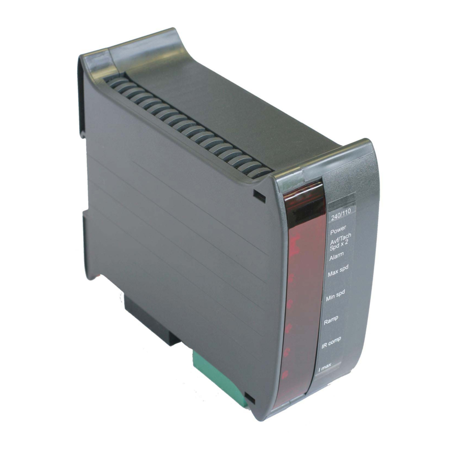
Summary of Contents for Sprint Electric 340
- Page 1 World Class Design | World Class Function | 30 Years Expertise in Industrial Motor Control DC MOTOR DRIVE 340 / 680 / 1220 Product Manual HG105266EN00 Issue 1 (02/2021)
- Page 2 Please read this information before installing or using the product. Install, use and maintain this product following the procedures provided. The manual(s) cannot provide all details, variations and contingencies required for your installation, operation and maintenance of this product or the apparatus with this product installed.
- Page 3 WARNING! Only qualifi ed personnel must install, operate and maintain this equipment. A qualifi ed person is someone technically competent and familiar with all safety information, established safety practices, installation, operation, maintenance and the hazards involved with this equipment and any associated machinery. Hazards This equipment can endanger life through rotating machinery and high voltages.
- Page 4 Weight Consideration should be given to the weight of our heavier products when handling. Risk assessment Under fault conditions or conditions not intended: the motor speed may be incorrect; the motor speed may be excessive; the direction of rotation may be incorrect; the motor may be energised.
-
Page 5: Table Of Contents
Contents: 1 Introduction 1 Introduction 2 Installation 2 Installation Motor installation ......................2 Drive installation ......................2 2.2.1 Initial settings - without power ..............2 2.2.2 Mechanical installation ..................4 2.2.3 Electrical installation ..................4 3 Operation 3 Operation Pre-operation motor check list ..................6 Operating the drive ....................... -
Page 6: Introduction
1 Introduction Introduction The 340 / 680/ 1220 DC Drive is a non-isolated speed controller for small brushed shunt wound or permanent magnet DC motors. This "non-isolated" drive has control signals that are NOT isolated from the mains supply, therefore, do not connect any of the terminals to earth or to other non-isolated equipment as when power is applied to the drive ALL terminals are at dangerous line potential. -
Page 7: Installation
3.4 A (340 drive), 6.8 A (680 drive), 12.2 A (1220 drive) Min spd * Minimum For example, to adjust the preset on a 340 drive for a motor with an armature 0 to 30% o USER ADJUSTMENTS current rating of 1.7 A, set it to 50%. Use a suitable current meter temporarily connected in series with the armature to achieve accurate settings. - Page 8 The suggested Commissioning strategy starts in the safest possible mode of operation and progressively exercises each element of the system to achieve full functionality. WARNING! When power is applied to the drive, ALWAYS use an insulated tool when adjusting the presets. DIN rail release catch USER ADJUSTMENTS Supply jumper: (LV60 model will indicate 60/30 Vac)
-
Page 9: Mechanical Installation
External RUN contact (Terminal 5) for electronic STOP/START * Potentiometer, graduated dial and knob - Sprint Electric part number: POTKIT EMC wiring: If the unit is going to be used in the domestic environment, then for installations in the EU, a supply filter is recommended in order to comply with EN6800-3. - Page 10 potentiometer ANTI-CLOCKWISE MID- WARNING! PERSONAL INJURY HAZARD Terminals A+, A-, F-, F+, N & L are at high potential. Do not touch the terminals or any connected conductor. DANGER! ELECTRIC SHOCK fuse HAZARD AC SUPPLY (optional) MOTOR MOTOR ARMATURE FIELD L1/L2/L3, A+/A- Use correctly rated cable - minimum 600 Vac, 1.5 x armature current Earthing: All control inputs to the drive are NON-ISOLATED.
-
Page 11: Operation
3 Operation Operation 3.1 Pre-operation motor check list With no power applied, complete the following check list: • Check for the correct insulation between individual motor elements, and between these elements and the earthed motor frame. Disconnect all drive cables before testing. - Page 12 340 / 680 / 1220 OFF: 40 to 100 V armature voltage range 90 to 200 V armature voltage range 340 LV60 / 680 LV60 / 1220 LV60 OFF: 10 to 25 V armature voltage range 23 to 50 V armature voltage range Adjust the Max spd potentiometer setting to achieve the required shaft speed.
-
Page 13: Options
4 Options Options • Speed Feedback selection: If the system is to use Tacho feedback you can now adjust for the tachogenerator's output voltage, and hence the speed of the motor: Run the drive in Armature Voltage feedback mode and check the polarity of the tacho using a voltmeter. -
Page 14: Specifications
(Vdc) (Adc) (Adc max) (kW / hp) 110 or 240 90–180 (200 V max) 0.55 / 0.75 340 LV60 30 or 60 24–48 (50 V max) 110 or 240 90–180 (200 V max) 0.75 / 1 680 LV60 30 or 60 24–48 (50 V max) - Page 16 We may, at our discretion, raise a charge for any faults without notifi cation. repaired that fall outside the warranty cover. www.sprint-electric.com Sprint Electric Limited, Peregrine House, Ford Lane, Ford, Arundel BN18 0DF, U.K. Tel: +44 (0)1243 558080 Fax:+44 (0)1243 558099 Email: info@sprint-electric.com...


Need help?
Do you have a question about the 340 and is the answer not in the manual?
Questions and answers