Table of Contents
Advertisement
Advertisement
Table of Contents
Troubleshooting

Related Manuals for Aim MYCHRON4 660


Summary of Contents for Aim MYCHRON4 660
- Page 1 USER MANUAL...
-
Page 2: Table Of Contents
1 – HOW TO INSTALL MYCHRON4 660 .............. 3 1.1 – How to install and replace the batteries ..........3 1.2 – How to install MyChron4 660 on Junior Dragsters ......5 1.3 – How to install the RPM wire ..............6 1.4 –... - Page 3 MyChron4 660 User Manual Release 1.03 4.4 – QMAn Data Analysis ................55 4.4.1 – Test/Run manager ................56 4.4.2 – Analysis View.................. 60 4.4.3 – Time Plot ..................62 4.3.4 – Histogram ..................69 4.3.5 – XY Plot .................... 71 4.3.6 –...
-
Page 4: How To Install Mychron4 660
1 – How to install MyChron4 660 Before installing MyChron4 660, please read these installation instructions carefully. It is very important that your MyChron4 660 is correctly installed in order to capture consistent and accurate data. Incorrect installation may result in system malfunction. - Page 5 MyChron4 660 User Manual Release 1.03 open here to change the battery To change battery, remove the two screws on the back of the display unit. A 9V battery will be connected to a two-wire power lead. Simply disconnect the battery from the lead and replace with a new battery.
-
Page 6: How To Install Mychron4 660 On Junior Dragsters
Behind the body cell on the vertical metal bulkhead which separates the racer’s seat from the engine is a commonly used location. More specifically, as shown in the following drawing, AIM recommends all MyChron4 660 users to install the gauge under the engine’s ON/OFF switch. -
Page 7: How To Install The Rpm Wire
Remember to insert the rubber wire-holder in order to protect the RPM wire against tears and cuts. While connecting the RPM wire to your MyChron4 660, please keep the cable as far as possible from the temperature ones. If the RPM and temperature wires are wrapped together, the temperature channels might be very noisy. -
Page 8: How To Install The Egt Thermocouple
MyChron4 660 User Manual Release 1.03 1.4 – How to install the EGT thermocouple The Exhaust Gas Thermocouple (EGT) has to be installed inside the exhaust header pipe at a distance of approximately 5.9“ (150 mm) from the exhaust port. - Page 9 MyChron4 660 User Manual Release 1.03 The EGT thermocouple may also be installed using a steel adapter which has to be welded to the exhaust header pipe, as described in the following drawing and explained below. Weld Make a 0.4” (10 mm) hole inside the exhaust header 1.
-
Page 10: How To Install The Cylinder Head Thermocouple
MyChron4 660 User Manual Release 1.03 1.5 – How to install the cylinder head thermocouple When using a Cylinder Head Thermocouple (CHT) sensor, always remove the spark plug washer before inserting the spark plug into the sensor. When tightening and loosening the spark plug, minimise movement of the sensor to avoid damage. -
Page 11: How To Install The Speed Sensor
MyChron4 660 User Manual Release 1.03 1.6 – How to install the Speed sensor In order to sample the dragster’s speed, you have to install a phonic wheel (jackshaft collar) on the jackshaft (¾” diameter) moved by the clutch. The movement of the jackshaft and the movement of the wheel are related to the crown/pinion ratio. - Page 12 MyChron4 660 User Manual Release 1.03 The speed kit is composed of 1 phonic wheel and 1 magneto resistive speed sensor. The phonic wheel is made of Teflon and is composed of two separate parts: an internal ring, which includes 4 magnets, and an external bushing, which protects the internal ring.
- Page 13 MyChron4 660 User Manual Release 1.03 To correctly install the speed kit, please follow these instructions: 1. To mount the phonic wheel on the jackshaft, please remove the pinion and insert the phonic wheel (internal diameter ¾”) on the jackshaft 2.
-
Page 14: How To Connect Cables To Mychron4 660
Once you have correctly installed all the sensors described above, you need to connect them to your MyChron4 660. On the backside of the display unit you have to plug the “2 temperatures split cable” to the connector labelled as “TEMPERATURE”... -
Page 15: How To Use Mychron4 660
MyChron4 660 User Manual Release 1.03 2 – How to use MyChron4 660 As you power on your MyChron4 660, the display shows the following information (described in the same order as they appear): 1. AIM MYCHRON4 660 Instrument name 2. -
Page 16: How To Switch On/Off The Gauge
If you wish to switch ON the gauge, press button ON/VIEW, if you wish to switch it OFF, keep >>/OFF pressed. Your MyChron4 660 has an automatic power down feature that turns the power off after 10 minutes of inactivity. -
Page 17: Configuration Functions
MyChron4 660 User Manual Release 1.03 2.3 – Configuration functions Before starting your system on-track, please configure your gauge in order to acquire correct data from your system. 2.3.1 – Configuration wizard You can enter the Configuration Menu pressing the MENU button. - Page 18 MyChron4 660 User Manual Release 1.03 Your configuration Wizard has now finished and your MyChron4 660 is ready to start running. Explanation about the configuration can be found in the Configuration Menu paragraph below. www.aim-sportline.com...
- Page 19 MyChron4 660 User Manual Release 1.03 Manual configuration Please, switch ON the gauge (press ON/VIEW) and enter Configuration Mode (push MENU/<< button) in order to set the configuration parameters (RPM scale, RPM factor, Wheel circumference, etc…). Buttons MENU/<< (back to previous option) and >>/OFF (forward to next option) are used to scroll through the configuration menu.
- Page 20 MyChron4 660 User Manual Release 1.03 Configuration Menu The Configuration Menu can be activated pressing MENU button. Once you have completed the configuration Wizard at least once, the MENU screen appears as in the picture here below: BackLight Track Name...
- Page 21 MyChron4 660 User Manual Release 1.03 The gauge’s display can be set to backlight display so that it is visible during night racing or in low-visibility conditions. Backlight To set the Night Vision ON or OFF, highlight backlight icon (Night Vision)
- Page 22 MyChron4 660 User Manual Release 1.03 Speed Setup function sets these parameters: Wheel circumference: this function allows to set the wheel circumference in inches. This parameter is fundamental to Speed Setup correlate the wheel angular speed and the dragster speed.
- Page 23 MyChron4 660 User Manual Release 1.03 The MyChron4 660 includes an internal run-counter which lets the user know the number of runs the gauge has recorded The date shown in the function name represents the engine Engine Pass Counter pass when you erased the run-counter.
- Page 24 RPM value sampled by your MyChron4 660. RPM Setup MyChron4 660 can be configured to manage a wide range of RPM (from 8,000 to 16,000). Please remember to insert a higher value than your Engine’s Maximum RPM to acquire correct data.
- Page 25 ON/VIEW to discard them. The system setup menu sets different options of the system: • Set Time/Date: your MyChron4 660 is equipped System setup with an internal clock which allows the user to see the current date and time on the display.
- Page 26 MyChron4 660 User Manual Release 1.03 battery: if battery is removed from the battery pack for more than 60 seconds (approximately) you will have to set date and time again. • Reverse: Use Reverse to switch display dots from white to black and vice-versa.
-
Page 27: The Display
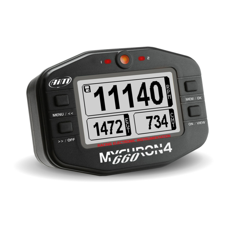
MyChron4 660 User Manual Release 1.03 2.4 – The Display The wide display with backlight shows information such as RPM (digital value), cylinder head temperature CHT (lower right corner of the display) and exhaust gas temperature EGT (lower left corner) When the disc icon appears in the upper left hand corner, the system has begun recording data. -
Page 28: Post Run Review
MyChron4 660 records RPM, 2 temperature inputs and speed at a sampling rate of 50 Hertz (50 times per second). These data can be recalled for analysis. MyChron4 660 splits data for runs: each run includes a few seconds before your launch, your pass and your coast down. - Page 29 MyChron4 660 User Manual Release 1.03 In the second part on top right the test number is indicated: Right below, in the third section, you see the labels referred to the values contained in the next section: Maximum RPM, Shaft, EGT(Exhausted Gas Thermocouple), and CHT...
- Page 30 MyChron4 660 User Manual Release 1.03 Pressing MEM/OK key for the second time, you pass on to values graph the graph page of RPM and Shaft. For the first 3 seconds the screen with the magnifying glass icons is shown (see image below).
- Page 31 MyChron4 660 User Manual Release 1.03 LEVEL TWO – 16,00 sec.zoom LEVEL ONE -19,2 sec. zoom LEVEL THREE – 12,8 sec.zoom LEVEL FOUR – 9,6 sec.zoom LEVEL FIVE – 6,4 sec.zoom LEVEL SIX – 3,2 sec. zoom www.aim-sportline.com...
-
Page 32: Gps Module And Mychron4 660
Release 1.03 3 – GPS Module and MyChron4 660 3.1 - How to connect GPS MODULE GPS Module can be connected to MyChron4 660 in different ways and with different peripherals. Connection with internal power The Figure below shows a CAN network powered by MyChron4 660 internal batteries: this powering reduces the all network autonomy, valuable in around two hours recording time. -
Page 33: Connection With External Power
User Manual Release 1.03 Connection with external power The figure below shows a CAN network where GPS Module and MyChron4 660 are externally powered (assuming a 12 Volts battery is available on Junior Dragster) 3.2 - How to install GPS module For a better reception please fix the Antenna GPS over the cockpit . -
Page 34: Configuration Wizard
MyChron4 660 User Manual Release 1.03 While the GPS receiver must be fixed through the implantation hole as in the figure below. Fix here the Antenna GPS 3.3 - Configuration Wizard No system configuration is needed. The system self configures at start up. -
Page 35: Mychron4 660 Data Visualization
MyChron4 660 User Manual Release 1.03 3.4 - MyChron4 660 Data visualization When GPS Module is connected to MyChron4 660, swiching the datalogger on GPS Module recognition window appears. • MyChron 4 660 and GPS Firmware version • USA =American Version / EU = European Version Pressing “ON/VIEW”... -
Page 36: Mychron4 660 Datakey For Data Download
WEAK signal is weak − GOOD reception is OK To come back to the first page click twice “ON/VIEW” button. 3.5 - MyChron4 660 Datakey for data download To download recorded data on your PC please refer to the chapter “Downloading data with MyChron4 660”... -
Page 37: Gps Module With Qman
MyChron4 660 User Manual Release 1.03 3.6 GPS Module with QMan Open a test containing GPS data with QMAN software some additional channels are shown: GPS Speed Speed measured through GPS signal GPS Nsat Number of satellites locked to GPS Module. Max accepted number of satellites is 9. - Page 38 MyChron4 660 User Manual Release 1.03 GPS Lon.Acc. Vehicle accelerations and decelerations GPS Slope Positive and negative slope of the track GPS Heading Route of the vehicle compared to the geographical North GPS Gyro Trajectory cornering speed expresses in degrees/second...
-
Page 39: Mychron4 660 And The Pc
Release 1.03 4 – MyChron4 660 and the PC MyChron4 660 is designed to interface with a PC. Using a DataKey it is possible to download the data stored in your MyChron4 660 to your PC for analysis using the QMAn analysis software. -
Page 40: How To Use Qman
Release 1.03 4.2 – How to use QMAn AIM has written a new software specific for dragster racing data called QMAn. The software is constantly updated to ensure it remains bug free, and can be downloaded free of charge at www.aim-sportline.com. -
Page 41: Qman Installation
“Warn – Prompt me each time to choose an action” option. Once this is done, please follow carefully these instructions. Close all running applications. Insert AIM software installation CD in your CD/DVD drive and, if “auto play” function is enabled installation will start automatically, otherwise double click on “SETUP”... - Page 42 MyChron4 660 User Manual Release 1.03 If you are installing AIM software for the first time the window on the right appears. It allows choose installation destination folder. Clicking on “Browse” button you can select the folder where to install the software. Clicking on “Next” button the software will be installed in C/program files/AIM folder, where “C”...
- Page 43 AIM software, the window on the right appears. Click on “Finish” button. Your installation is complete. If you are installing AIM software for the first time, USB driver installation starts and the window on the right appears. Please disconnect any USB cable from your PC and click on the “Start”...
- Page 44 MyChron4 660 User Manual Release 1.03 Click “Continue Anyway” button Click “Continue” button. A series of three panels appears to assist you for the next steps. Now you can plug the the DataKey into the PC USB port. Wait a few seconds for the next panel.
- Page 45 MyChron4 660 User Manual Release 1.03 This panel indicates that your instrument is connected to and recognized by the PC. Please note: after the end of this procedure, if you connect your logger to another USB port of the same PC, the system may ask you again for driver installation.
- Page 46 MyChron4 660 User Manual Release 1.03 Click “Finish” button. Click “OK” button. Click “Finish” button. www.aim-sportline.com...
-
Page 47: Troubleshooting
Here on the right you see the default icon of QMAn software. Please refer to the software user manual for further information. Once the first installation is successfully completed, QMAn software updating (remember to periodically check www.aim-sportline.com) will skip the steps regarding the USB driver installation. 4.3.2 – Troubleshooting If USB driver installation procedure ended incorrectly you can start the “Repair... -
Page 48: Installation Under Microsoft Vista
PC’s are normally sold with this type of account. This is explained in greater detail below. AIM software installation will create a new icon on your desktop to allow you starting the USB driver installation with the special “Run as Administrator”... - Page 49 MyChron4 660 User Manual Release 1.03 In case of the first AIM software installation on your computer, the window on the right appears. It allows you to choose the installation destination folder. By clicking the “Browse” button you can select the folder in which to install the software.
- Page 50 After the installation, in case of software upgrading the window on the right appears. Click on “Finish” button. AIM Software installation is completed. In case of a first installation of AIM software, the window on the right appears. • Click on “OK” button to continue installing the software.
- Page 51 This window shows how to perform the <Run as Administrator> procedure; click on “OK” button to continue. Click “Finish” AIM-USB driver installation with <Run as Administrator> procedure As explained in the figure on the right go to desktop, right click AIM_USB_2008 icon and select “Run as...
- Page 52 MyChron4 660 User Manual Release 1.03 Click “YES” to continue. Disconnect any USB cable and click the “START” button. Close all other applications and click the “START” button once more to begin the installation of AIM-USB drivers. www.aim-sportline.com...
- Page 53 MyChron4 660 User Manual Release 1.03 Click the “OK” button. Click on “Install this driver software anyway.” click on the “Continue” button. www.aim-sportline.com...
- Page 54 USB driver one. Please see each software user manual for further information. Once the first installation is successfully completed, any AIM software upgrading (remember to periodically check www.aim-sportline.com) will skip the steps regarding the USB driver installation.
-
Page 55: Troubleshooting
MyChron4 660 User Manual Release 1.03 4.3.5 – Troubleshooting If the procedure ended incorrectly for any reason, you can start the “Maintenance” Procedure repeating the “Run as Administrator” procedure. Click on the “OK” button. The panel on the right appears. Click on “Reinstall Driver.”... -
Page 56: Qman Data Analysis
MyChron4 660 User Manual Release 1.03 4.4 – QMAn Data Analysis Analysis is fundamental to seting up your vehicle. You will analyze your racing data by using the included QMAn software. This chapter describes how to use QMAn in order to obtain the maximum amount of information from the test data. -
Page 57: Test/Run Manager
MyChron4 660 User Manual Release 1.03 4.4.1 – Test/Run manager When you open QMAn, the following screenshot will appear. It features a toolbar, a left and a right part. The right part shows you the runs you already downloaded to your PC. The left part lets you refine the list of runs displayed on the right part... - Page 58 Properties – opens a window that lets you modify some run file properties Import – lets you add some run files to your run database from an external file Export – lets you export some run files from your run database (e. with the aim to move them to another PC) Remove –...
- Page 59 AIM email address, just change it with the recipient you wish to send .drk file(s) to. If you need assistance from AIM, just select the “Send files by e-mail to AIM” option. We will receive just the test file and logger information. No personal data will be sent to us.
- Page 60 MyChron4 660 User Manual Release 1.03 want software preferences, please close all open tests and select “Preferences” from the top toolbar. The following picture will appear. run length vehicle type, as many features in the Please choose the correct software were specifically developed for different vehicles and run lengths.
-
Page 61: Analysis View
MyChron4 660 User Manual Release 1.03 4.4.2 – Analysis View Once a run has been loaded, the “Analysis View” window will be prompted as shown in the screenshot below. There are up to 8 Analysis Views available. Any of them is customizable independently from the others, hence enabling you to have different analysis templates always available. - Page 62 MyChron4 660 User Manual Release 1.03 Three different types of plot graph are available: Time, XY and Histogram; clicking on the Plot type toolbar button you can switch between each of these three graphs . We’ll be immediately explaining the Time Plot graph, to follow later with XY and Histogram.
-
Page 63: Time Plot
MyChron4 660 User Manual Release 1.03 4.4.3 – Time Plot The “Time plot” feature allows the user to plot a logged channel versus time. Left click inside the graph to show a vertical cursor. Along the horizontal axes the time and distance (calculated from the start line) value corresponding to that position will be shown. - Page 64 MyChron4 660 User Manual Release 1.03 The user may choose the channel to be plotted on the graph by left-clicking on the channel name inside the “channels list” window located in the upper left corner of the “Time plot” window.
- Page 65 MyChron4 660 User Manual Release 1.03 By clicking the small coloured button next to each channel name you can choose the plot colour of the channels itself. The click on the colour button prompts the following window. In the lower part of the “Time plot” window it is displayed the “Run toolbar”, which is a graph showing the complete time history of the loaded run.
- Page 66 MyChron4 660 User Manual Release 1.03 The width of the data window can be modified. QMAn allows the user to choose among 7 predefined zooms. You can view a 2 second window, and windows for runs spanning 4, 6, 8, 10, 14 and 20 seconds. For instance, if you were looking at a graph inside a 10 seconds window and you click the “Zoom in”...
- Page 67 MyChron4 660 User Manual Release 1.03 Plot settings can be modified through the Settings command in the toolbar. The following window is prompted. Kindly notice that there are parts of this window that are different for XY graphs and Histogram graphs. These differences will be explained later.
- Page 68 MyChron4 660 User Manual Release 1.03 able to use different views to plot different information, always ready for a quick interpretation of data. Below are some other settings that can be accessed through the channels list and plot settings. Line width settings refer to channels traces.
- Page 69 MyChron4 660 User Manual Release 1.03 Double click the 3D color scale to show its settings window. Through this window it is possible to set the bands number and the bands thresholds. www.aim-sportline.com...
-
Page 70: Histogram
MyChron4 660 User Manual Release 1.03 4.3.4 – Histogram While showing a histogram plot you’ll be able to see how long a channel remains within a certain band. In the following screenshot the RPM histogram lets you visualize which RPM ranges are used the most in the run, providing you with more information for tuning your engine. - Page 71 MyChron4 660 User Manual Release 1.03 The next screenshot shows you that the parameters that can be set for this plot are the histogram computation base (time or percentage) and the beans number. Even the histogram plot can show a 3D channel. In this case, within a single horizontal bar you can see multiple sub bars with different colours, the amplitude of each sub bar lets you understand a distributed histogram of the 3D channel.
-
Page 72: Xy Plot
MyChron4 660 User Manual Release 1.03 4.3.5 – XY Plot The XY plot or scatter plot shows the traces of the enabled channels versus one selected X channel. If you check the Cursor button in the run history bar you can move the cursor within the run history bar and see what happens inside the XY plot. - Page 73 MyChron4 660 User Manual Release 1.03 The next screenshot shows you that the settable parameters of the XY plot are the horizontal axis channel and the drawing mode: lines, dots or circles (and their dimensions). The XY plot lets you show a 3D channel as well as the other two plots.
-
Page 74: Channel Info
MyChron4 660 User Manual Release 1.03 4.3.6 – Channel info There are a number of parameters that can be modified for every channel, you may right click on the channel name inside the “Available measurements” toolbar or click the “Channels” button inside the buttons toolbar. The “Set Channels”... -
Page 75: How To Set The Time Slip Info
MyChron4 660 User Manual Release 1.03 4.3.7 – How to set the time slip info Once the time slip has been handed to the racer, he/she can manually input pieces of information from the time slip into the analysis software. QMAn has been designed to allow you to insert useful data (reaction time, 60’... -
Page 76: How To Set Weather Station Data
MyChron4 660 User Manual Release 1.03 4.3.8 – How to set weather station data The user is allowed to set the weather conditions, in order to be able to correlate the test performances (reaction time, linear acceleration, engine’s setup) to the atmospheric conditions. -
Page 77: Test Loaded View
MyChron4 660 User Manual Release 1.03 4.3.9 – Test Loaded View This view shows a report form of all the information bound to every run loaded for analysis. If you red-highlight a line of a run you can click on one of the toolbar buttons to open the settings window already shown. - Page 78 MyChron4 660 User Manual Release 1.03 The first column in the report includes the descriptions, and then you will see one column for each run you load . www.aim-sportline.com...
-
Page 79: Run Info
MyChron4 660 User Manual Release 1.03 4.3.10 – Run Info This window lets you enter general information on the performed run. www.aim-sportline.com... -
Page 80: Time Slip
MyChron4 660 User Manual Release 1.03 4.3.11 – Time Slip You can store all the information bound to the time slip that affect the time plot. www.aim-sportline.com... -
Page 81: Tachometer
MyChron4 660 User Manual Release 1.03 4.3.12 – Tachometer You can also store all the readings of the tachometer that matter most, even at launch. www.aim-sportline.com... -
Page 82: Weather
MyChron4 660 User Manual Release 1.03 4.3.13 – Weather You can record all the important information coming from a weather station. 4.3.14 – How to send the test file via E-mail If you have a problem with a test file (i.e. you can’t open it, the recorded data do not seem to be correct or you simply need help) you may send us the file via e- mail with the simple click of a button. -
Page 83: Maintenance
Provided adequate care is taken with the display unit and components, the only maintenance will be to upgrade the firmware when upgrades are released by AIM and to change the display unit batteries when the low battery indicator appears on the top right hand corner of the display. - Page 84 MyChron4 660 User Manual Release 1.03 Choose this option upgrade DataKey and press “Proceed” Connect your Mycron4 660 to the DataKey. • Turn on the gauge • Now the firmware on your Mycron4 660 will update. Attention: At the end of the process your PC monitor will show “END.”...
-
Page 85: Appendix A: Technical Characteristics
MyChron4 660 User Manual Release 1.03 Appendix A: Technical characteristics Connector details (Temperature channel) Pin Function Function Female 7-pins connector pin out (external view) Note: TC = Thermocouple TR = Thermo resistor www.aim-sportline.com... - Page 86 MyChron4 660 User Manual Release 1.03 Connector details (Speed channel) Pin Function Function Speed n.c. Female 4-pins connector pin out (external view) Connector details (Exp/PC) Pin Function Function CAN + CAN - +VBext Female 5-pins connector pin out (external view)
- Page 87 1 MB PC interface USB port through Datakey Sampling freq. per channel 50 Hz Maximum total sampling frequency 80 Hz Other characteristics Value MyChron4 660 dimensions 123,5x87x46 mm 4.86x3.425x1.81 in Display dimensions 78,8x49,2 mm 3.10x1.94 in Environmental IP 65 Weight 300 g (batteries included) 10.58 oz ~ 0.66 oz...
Need help?
Do you have a question about the MYCHRON4 660 and is the answer not in the manual?
Questions and answers