Table of Contents
Advertisement
Advertisement
Table of Contents

Related Manuals for Rugged Radios GMR2


Summary of Contents for Rugged Radios GMR2
- Page 1 GMR2 USER MANUAL...
- Page 2 1-7, 15-22 or RP15-22, and RUGGED which comprise the GMRS channels of the GMR2. Serious penalties may result from unlicensed use of GMRS channels, in violation of FCC rules, as stipulated in the Communications Act’s Sections 501 and 502 (amended).
-
Page 3: Table Of Contents
CONTENTS User Safety Information Specifications Package Includes General Charging Your Battery Pack Transmitter Charging Preparation Receiver Notes Charging Operation Accessories Connections Battery Pack Belt Clip Ext. Mic/Speaker Getting Acquainted Front Panel Operation Side Panel Operation LCD Display Keypad Functions Working Mode Set Menu Mode Menu Operation Detailed Function Description... -
Page 4: User Safety Information
USER SAFETY INFORMATION • Please read the following brief instructions, non-compliance with these rules may cause danger or violate the law. • Obey the local government regulation before using this radio, improper use may violate the law and be punished. •... -
Page 5: Package Includes
PACKAGE INCLUDES Please check if any damage to the package when you receive it. Carefully unpack the transceiver. We recommend that you check the items listed in the following table. If any items are missing or damaged during shipment, please contact with your local dealer immediately. •... -
Page 6: Charging Your Battery Pack
CHARGING YOUR BATTERY PACK CHARGING PREPARATION Precaution: The supplied battery pack of this radio is a high –performance Li-ion with 7.4V standard voltage 1400mAh high capacity in a very compact package. Under normal use, the battery pack may be used for approximately 500 charge cycles and more, after which operating time maybe expected to decrease. -
Page 7: Charging Operation
CHARGING YOUR BATTERY PACK CHARGING OPERATION After installing the battery pack, if the battery icon shows [ ], it means that the battery pack is out of power. Please charge it. Charging indicator light conditions: Indicator Display Status Charging Green Completed Battery Tips •... -
Page 8: Accessories Connections
ACCESSORIES CONNECTIONS BATTERY PACK Align the two grooves of battery and the guide rail on the back of the aluminum shell, ensure full contact and in parallel, then push the battery up to the radio base along the rail on the back of the aluminum shell, until the battery latch locks up. (Picture 1) To remove the battery, please make sure the radio is closed, push the battery latch down, and make sure the radio and battery is on the releasing state, and then push the battery out from the radio. -
Page 9: Belt Clip
ACCESSORIES CONNECTIONS BELT CLIP Align the two holds of belt clip and the two holes of the radios, fix them with the supplied M2.5x5 screws. Loosen the screw set to remove belt clip. (Picture 5) PICTURE 5... -
Page 10: Ext. Mic/Speaker
ACCESSORIES CONNECTIONS EXTERNAL MICROPHONE/SPEAKER Open the cover of the microphone/speaker jack and insert the microphone/speaker plugs into the jack. (Picture 6) • Using the external headset or mic/speaker will affect the water-tightness performance of radio. A/ B PICTURE 6... -
Page 11: Getting Acquainted
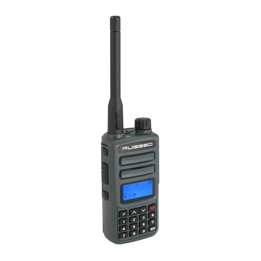
GETTING ACQUAINTED FRONT PANEL OPERATION ANTENNA POWER/ VOLUME BUTTON INDICATOR SPEAKER MICROPHONE LCD DISPLAY FUNCTION/ENTER KEY A/B SWITCH KEY/EXIT NUMBERAL KEY... -
Page 12: Side Panel Operation
GETTING ACQUAINTED SIDE PANEL OPERATION 1. Flashlight 2. Activates 1750HZ for repeater access MIC/SP and transmit DTMF and 2/5 tone signaling The jack provides connection points for microphone audio, earphone audio, speaker and Press it to transmit and release it to receive program cable. -
Page 13: Lcd Display
GETTING ACQUAINTED LCD DISPLAY You will see various icons shown on the screen when power is on. The following table can help you identify icons’ meaning which display on LCD. - Page 14 GETTING ACQUAINTED LCD DISPLAY Icons Function Operating band signal & power meter High TX power active Dual watch/standby active RX power save active Scanning active Narrow/wide band mode active Repeater shift direction Keypad lock Battery power indicator...
-
Page 15: Keypad Functions
GETTING ACQUAINTED KEYPAD FUNCTIONS (1) Switch the A or B Enter menu mode/ frequency to be the Upper menu item, Lower menu item, Press key confirm “Operating” Band channel or frequency channel or frequency. the setting (2) EXIT function Frequency/ Frequency/ Frequency/ Frequency/... - Page 16 GETTING ACQUAINTED KEYPAD FUNCTIONS (CONT.) Frequency/ Frequency/ Frequency/ Frequency/ Frequency/ Press key Channel No. Channel No. Channel No. Channel No. Channel No. entry “0” entry “6” entry “7” entry “8” entry “9” Enter dual Press Enter DTMF wait/standby Enter LED item Enter color item Enter beep item 2T &...
-
Page 17: Working Mode
WORKING MODE FREQUENCY MODE (LSO) Under this mode, you can use [ ] /[ ] key to change the frequency or input the frequency by keypad directly and store channels. FREQUENCY–CHANNEL MODE (MR) When you have stored a memory channel at least and under VFO mode, press [ ] key to enter MR mode. -
Page 18: Set Menu Mode
SET MENU MODE LCD Display Available Values Description of Function SCAN Frequency/Channel Scan SQUELCH SQL Level Setting 1 Channel MONITOR Dual Wait/Standby 2 Channel BACKLIGHT On/Auto/Off LED Display Mode DIMMER Background Light Color BEEP On/Off Keypad Beeper Setting ROGER BP On/Off Transmit Over Beeper AUTOLK... -
Page 19: Menu Operation
SET MENU MODE MENU OPERATION Under Standby Mode, press [ ] to enter menu setting, LCD displays “MENU”. Press [ ] or [ ] to select the desired menu item. LCD displays current setting of selected item. Press [ ] to enter and then press [ ] or [ ] to select the desired setting. -
Page 20: Detailed Function Description
DETAILED FUNCTION DESCRIPTION Scan (SCAN---MENU 1) Functions: under VFO/MR/CH mode, the transceiver allows you to scan the entire current operating band and memory channels. Enter MENU 1 and press [ ] key to start scanning. When you start scanning, press [ ] /[ ] key to change direction. - Page 21 DETAILED FUNCTION DESCRIPTION LED Display Mode (BACKLIGHT---MENU 4) Functions: Select the LED/Keypad Lamp mode. Enter MENU 4 to select LED display mode. Default: AUTO Background Light Color (DIMMER---MENU 5) Functions: Choose LED background light color. Enter MENU 5 to select background light color. Default: 7 Keypad Beeper Setting (BEEP---MENU 6) Functions: Enable/disable the keypad beeper.
- Page 22 DETAILED FUNCTION DESCRIPTION Voice Prompt (VOICE---MENU 9) Functions: Enable/disable voice prompt. Enter MENU 9 to set VOICE. Default: ON 10. Battery Power Voltage (VLT---MENU 10) Functions: Check battery voltage. Enter MENU 10 to check battery voltage. 11. TX/RX Tone Coder, Tone Search Scanning, Tone Calling (C-CDC---MENU 11) Function 1: CTCSS/DCS Operation.
- Page 23 DETAILED FUNCTION DESCRIPTION 13. TX Tone Coder, Tone Search Scanning, Tone Calling (T-CDC---MENU 13) Function 1: CTCSS/DCS Operation. Many repeater systems require that a very-low- frequency audio tone be superimposed on your FM carrier in order to activate the repeater. This helps prevent false activation of the repeater by radar or spurious signals from other transmitters.
-
Page 24: Ctcss Tone Frequency
CTCSS TONE FREQUENCY CTCSS TONE FREQUENCY (Hz) 67.0 69.3 71.9 74.4 77.0 79.7 82.5 85.4 88.5 91.5 94.8 97.4 100.0 103.5 107.2 110.9 114.8 118.8 123.0 127.3 131.8 136.5 141.3 146.2 151.4 156.7 159.8 162.2 165.5 167.9 171.3 173.8 177.3 179.9 183.5 186.2... -
Page 25: Dcs Code
DCS CODE DCS CODE... -
Page 26: Advanced Functions
ADVANCED FUNCTIONS Keypad Lock Setting Under standby mode, press [ ] for 2 seconds to lock and unlock the keypad. [ ] will be displayed at the top of LCD when keypad is locked. FM Radio Function On/Off Radio Receiver: Under standby mode, hold [ ] to open FM radio functions. -
Page 27: Specifications
SPECIFICATIONS GENERAL Channels Operating voltage 7.4VDC Operating temperature -10°C ∼ +50°C Weight 106g/3.74oz (including battery and antenna) Dimension 116x53x36mm TRANSMITTER RX: 136-174 & 400-480MHz Frequency TX: GMRS Modulation type Spurious power ≤ -15dB Modulation noise < -40dB Modulation distortion < 5% Frequency stability 5ppm Max Fr. -
Page 28: Receiver
SPECIFICATIONS RECEIVER RX: 136-174 & 400-480MHz Frequency TX: GMRS Sensitivity ≤0.2 μ V Occupied bandwidth ≤16KHz Selectivity ≥65dB Intermediation ≥55dB Audio power >500m W Audio distortion ≤10% Frequency stability 5ppm Current Standby: 60mA working: 250Ma Audio response (300-3400Hz) +7∼ - 12.5dB... -
Page 29: Notes
NOTES...
Need help?
Do you have a question about the GMR2 and is the answer not in the manual?
Questions and answers