Advertisement
Quick Links
ADULT ASSEMBLY REQUIRED DUE TO THE PRESENCE OF SMALL PARTS, SHARP
POINTS, SHARP EDGES AS RECEIVED
If you have any questions regarding assembly or if parts are missing, DO NOT return this item to the
store where it was purchased. Please call our toll-free customer service number and have your
instructions and parts list ready to provide the model name, part name or factory number:
Pacific Standard Time: 8:30 a.m. - 4:30 p.m., Monday - Friday
Or visit our web site 24 hours a day, 7 days a week for product assistance at
THIS INSTRUCTION BOOKLET CONTAINS IMPORTANT SAFETY INFORMATION.
Thomasville™ is a trademark of HHG IPCo, LLC. ©HHG IPCo, LLC. thomasville.com
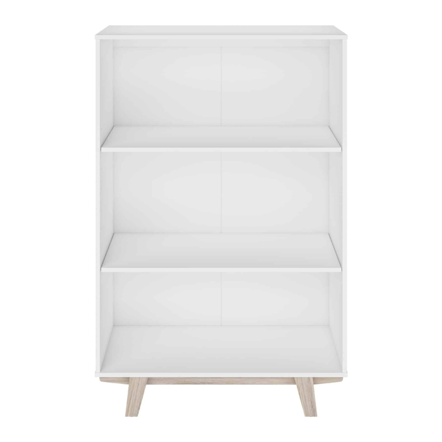
Whitney Bookcase
Model # SPLS-WHBK-TV
1-866-942-5362
www.whalenfurniture.com
Or e-mail your request to parts@whalenfurniture.com
PLEASE READ AND KEEP FOR FUTURE REFERENCE.
Date 2021-02-24
LOT NUMBER:
DATE PURCHASED: /
Rev. 0001-A
/
Advertisement

Related Manuals for Thomasville Whitney Bookcase SPLS-WHBK-TV


Summary of Contents for Thomasville Whitney Bookcase SPLS-WHBK-TV
- Page 1 Or visit our web site 24 hours a day, 7 days a week for product assistance at www.whalenfurniture.com Or e-mail your request to parts@whalenfurniture.com THIS INSTRUCTION BOOKLET CONTAINS IMPORTANT SAFETY INFORMATION. PLEASE READ AND KEEP FOR FUTURE REFERENCE. Date 2021-02-24 Rev. 0001-A Thomasville™ is a trademark of HHG IPCo, LLC. ©HHG IPCo, LLC. thomasville.com...
-
Page 2: Special Note
M A X I M U M R E C O M M E N D E D W E I G H T L O A D S MANUFACTURER: Whalen Furniture Manufacturing CATALOG: Whitney Bookcase MODEL # SPLS-WHBK-TV MAXIMUM LOAD 22.7 kg / 50 lb. THIS UNIT IS INTENDED ONLY FOR USE WITHIN THE MAXIMUM WEIGHTS INDICATED. - Page 3 IMPORTANT Before you begin: Open, identify and count all parts prior to assembly. Lay out parts on a flat and non- abrasive surface. You will need the parts identified on page 5 and 6 of this instruction manuals. NOTE: IT IS VERY IMPORTANT TO USE GLUE WITH DOWELS. EXCESS GLUE CAN BE WIPED OFF WITH DAMP CLOTH.
- Page 4 FURNITURE TIPPING RESTRAINT YOUNG CHILDREN MAY BE INJURED BY TIPPING FURNITURE AND YOU MUST USE THIS TIPPING RESTRAINT TO ATTACH THIS UNIT TO THE WALL, TO PREVENT ACCIDENTS AND/OR INJURIES. THIS HARDWARE MUST PROPERLY INSTALLED (FOLLOW DIRECTIONS IN ORDER ON THIS INSTRUCTIONS), TO PROVIDE PROTECTION AGAINST THE UNEXPECTED TIPPING OF FURNITURE DUE TO IMPROPER USE.
- Page 5 Parts and Hardware List Please read completely through the instructions and verify that all listed parts and hardware are present before beginning assembly. A- Top Panel (Qty. 1) B- Bottom Panel (Qty. 1) C- Top Back Stretcher (Qty. 1) D- Left Side Panel (Qty. 1) E- Right Side Panel (Qty.
- Page 6 Parts and Hardware List Please read completely through the instructions and verify that all listed parts and hardware are present before beginning assembly. (1) Cam Lock (2) Cam Bolt (3) M8 x 30 mm Wood Dowel (Qty. 9+1 extra) (Qty. 9+1 extra) (Qty.
- Page 7 Assembly Instructions NOTE: Please do not fully tighten all bolts until you finish assembling all parts. Once assembled, go back and fully tighten all bolts. This will make the assembly easier. 1. Unpack the unit and confirm that you have all the hardware and required parts. Assemble the unit on a carpeted floor or the empty carton to avoid any scratch.
- Page 8 Assembly Instructions The pilot holes for back panel face outward. 4. Align and attach the Top Back Stretcher (C) between the Side Panels (D and E) by engaging two Cam Locks (1). (Refer to page 3 on Cam Lock system operation supplement). 5.
- Page 9 Assembly Instructions 6. Using the wood dowels as a guide, align and attach the Bottom Panel (B) to the assembled Side Panels (D and E) with four 50 mm Screws (4). Tighten the screws with a Phillips screwdriver. 7. Glue two 30 mm Wood Dowels (3) into the pre-drilled holes on the ends of each Base Short Stretcher (I).
- Page 10 Assembly Instructions 9. Fasten the Legs (J and K) to the Base Long Stretchers (H) with eight 38 mm Bolts (10) and eight Washers (11 and 12). 10. Stand the assembled base upright and glue four 30 mm Wood Dowels (3) into the inner holes on the Base Stretchers (H and I).
- Page 11 Assembly Instructions 11. Using the wood dowels as a guide, align and attach the assembled Base Stretchers (H and I) to the Bottom Panel (B) and tighten them with fourteen 38 mm Screws (5). The adhesive tape faces outward. 12. Now, go back and securely tighten all the bolts and screws. Make sure that all the parts are tight and there are no gaps between the parts.
- Page 12 Assembly Instructions 14. Ask for assistance to stand the unit upright. 15. Insert four Shelf Supports (8) into the holes at the desired height inside each side panel. Make sure you place four shelf supports in the same level, so the shelf is not tilted. Tilt and rest the Adjustable Shelves (F) onto the Shelf Supports (8) and secure them (F) into place with 12 mm Flat Head Screws (6).
- Page 13 Assembly Instructions Wooden stud Wall Short screw Wall Metal bracket Metal bracket Nylon strap Long screw Floor leveler Tools required (not provided): Phillips screwdriver, stud finder, tape measure, pencil, power drill and 1/8” drill bit. 17. Position the unit at the desired location against a wall. If necessary, adjust the Floor Levelers at the bottom of the Legs (J and K) to level the unit.
-
Page 14: Quality Guarantee
Care and Maintenance Use a soft, clean cloth that will not scratch the surface when dusting. Gently rub the surface with a soft dry cloth, soft damp cloth, or soft damp cloth with neutral detergent, and then dry it well. ...
Need help?
Do you have a question about the Whitney Bookcase SPLS-WHBK-TV and is the answer not in the manual?
Questions and answers