Table of Contents
Advertisement
Quick Links
©2020
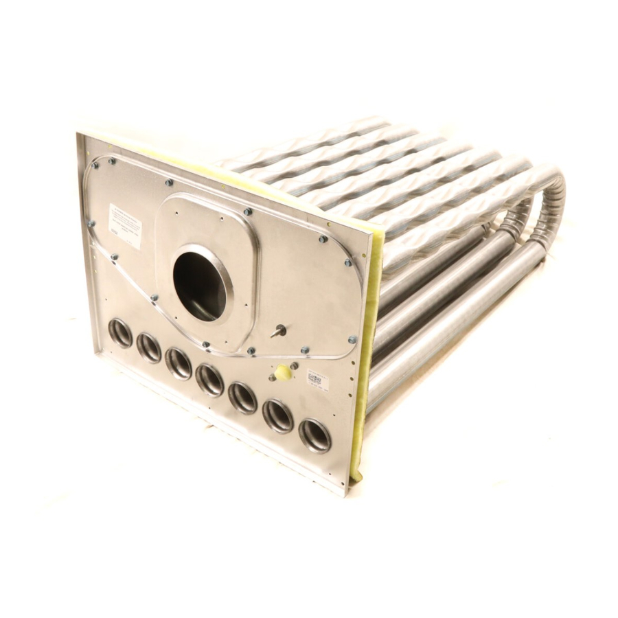
INSTALLATION INSTRUCTIONS FOR HEAT EXCHANGER REPLACEMENT KIT
USED ON LG/KG/ZG 036, 048, 060, 072, 074 PACKAGED ROOFTOP UNITS
Shipping and Packing List
Package 1 of 1 contains:
1- Heat exchanger assembly
1- Bag assembly containing:
22-Screws
1-CAB gasket
6-Seals (mastic)
5-Wire ties
1-Foam PVC tape (17" length)
Check packaging for shipping damage. Contact the last
carrier immediately if any shipping damage is found.
Application
See table for usage.
Heat Output
Cat. No. / Ass'y No.
99W41 / 610414-01
99W42 / 610414-02
99W43 / 610414-03
10M86 / 610414-04
13J82 / 610414-05
13J83 / 610414-06
13U10 / 610414-07
16G31 / 610414-08
150K 4 Stg. Stainless Steel
WARNING
Improper installation, adjustment, alteration, ser
vice or maintenance can cause property damage,
personal injury or loss of life. Installation and ser
vice must be performed by a licensed professional
HVAC installer or equivalent, service agency, or the
gas supplier
CAUTION
As with any mechanical equipment, contact with
sharp sheet metal edges can result in personal in
jury. Take care while handling this equipment and
wear gloves and protective clothing.
PACKAGED UNITS KITS
AND ACCESSORIES
507095-03
12/2020
Supersedes 507095-02
Material
KBtuh
150
Aluminized
105/108
Aluminized
65/70
Aluminized
65/70
Stainless Steel
105/108
Stainless Steel
150
Stainless Steel
108K NOX
Aluminum
ZG only
LG/KG-Before Removing Heat Exchanger
Note - Do not damage roofing surface during
replacement.
1- Disconnect all electrical power to unit and turn off
main gas valve.
2- Disconnect power at the main breaker if the external
disconnect is installed on the gas inlet mullion.
3- Disconnect gas inlet pipe at gas valve.
4- Open or remove heat and compressor access
panels. See figure 1.
REMOVE PANELS - LG/KG
HEAT ACCESS
PANEL
5- Remove the gas inlet mullion. See figure 1. If conduit
is run to the mullion, move the mullion out of the way.
Disconnect wiring and remove conduit if necessary.
6- Disconnect P19 from J19. See figure 2.
7- Disconnect
wiring
combustion air blower prove switch, and flame rollout
switch. On LGH/KG/ZG units, disconnect wiring to
the primary limit. See figure 2. On LGM150 units,
remove the primary limit.
Note - Wires are marked for identification during
reassembly.
8- Remove the two screws securing the combustion air
blower prove switch. Discard the switch if tabs are
broken. Retain the switch for reassembly if tabs are
intact. See figure 2.
9- Disconnect the air tubing to the fitting on the
vestibule. See figure 3.
Page 1
HEAT EXCHANGER
REPLACEMENT KIT
GAS INLET
COMPRESSOR
MULLION
ACCESS PANEL
FIGURE 1
to
ignitor,
flame
sensor,
Advertisement
Table of Contents

Related Manuals for Lennox 99W41

Summary of Contents for Lennox 99W41
- Page 1 HEAT ACCESS COMPRESSOR MULLION PANEL ACCESS PANEL See table for usage. Heat Output Cat. No. / Ass'y No. Material KBtuh 99W41 / 610414-01 Aluminized 99W42 / 610414-02 105/108 Aluminized 99W43 / 610414-03 65/70 Aluminized 10M86 / 610414-04 65/70 Stainless Steel...
- Page 2 DISCONNECT WIRING - LG/KG/ZG COMPRESSOR SECTION HEAT SECTION PRIMARY LIMIT PRIMARY LIMIT LGH/KG/ZG COMBUSTION AIR BLOWER PROVE SWITCH FLAME FLAME SPARK ROLLOUT SENSOR IGNITOR SWITCH FIGURE 2 10- Remove the burner box assembly. Retain six screws 13- Remove J19 from the division panel between the holding the assembly in place.
- Page 3 Horizontal Air Discharge - Direct Drive Blower: DIRECT DRIVE BLOWER REMOVAL - LGH/KG 1- LGH/KG Units - Unplug the motor harness and remove 6 screws on the base of the blower housing. See figure 6. Lift the back side of the housing and remove from unit. 2- LGM Units - Unplug the power and control harnesses to the motor.
- Page 4 9- Check for gas leaks at gas connections. LG/KG - Install New Heat Exchanger 10- Start unit blower according to unit installation 1- Install replacement heat exchanger. Lift the back of instructions. Check for air leaks out of the gas heat the heat exchanger over the supports and push area.
- Page 5 ZG - Remove Heat Exchanger REMOVE PANELS - ZG 1- Turn main manual shut-off valve off and turn off electrical supply to unit. 2- Open access panels as shown in figure 8. IMPORTANT - Remove and retain the speed nut that holds the heat exchanger bracket to the panel.
- Page 6 12- Start unit in heating mode according to unit ZG - Replace Heat Exchanger installation instructions. Check for proper operation 1- Install the combustion air inducer gasket, provided in of gas heat using lighting sequence provided in the this kit, and the previously removed combustion air unit installation instructions or lighting instruction blower.
- Page 7 HEAT SECTION - ZG ROTATE TWO PARTS OF THE FRAME OUT OF THE WAY BEFORE REMOVING OR INSTALLING HEAT EXCHANGER FIGURE 11 Page 7...
Need help?
Do you have a question about the 99W41 and is the answer not in the manual?
Questions and answers