
Related Manuals for ELGO Electric P8822-000-R Series


Summary of Contents for ELGO Electric P8822-000-R Series
- Page 1 P8822-000-R SERIES Dual axes position controller • 2 or 3 switched speed operation • manual inching mode • single set operation • 200 line program memory P8822-000-P-D_25-04...
-
Page 2: Table Of Contents
Contents: 1. SHORT DESCRIPTION 2. FUNCTIONS 2.1 Two speed operation (switched) 2.2 Three speed operation (switched) 2.3 Setting Datum/Reference 2.4 Encoder pulse monitoring 2.5 Error messages 3. FRONT VIEW/CONTROL ELEMENTS 3.1 Function of the displays 3.2 Function of the keypad 4. - Page 3 R28 SYSTEM REGISTER 3 R88 SYSTEM REGISTER 4 8. FUNCTION OF INPUTS (ST3 CONNECTIONS) 9. FUNCTIONS OF THE OUTPUTS (ST4 / ST6 CONNECTIONS) 11. CONNECTIONS 12. TECHNICAL SPECIFICATIONS 13. INSTALLATION AND WIRING 14. ONLY FOR SERVICE 15. TYPE DESIGNATION 16. LIABILITY EXCLUSION / GUARANTEE...
-
Page 4: Short Description
1. Short description The dual axes position controller P8822 is the consistent advancement of the proven 88P2. Substantial characteristics: • extensive standard functions • manual inching mode via keypad (with keys 7, 8, 9, NR) for X and Y axis •... -
Page 5: Setting Datum/Reference
2.3 Setting Datum/Reference Datum can be set in a variety of ways. The method is selected in Register R8/3 R8 = XX0XXX – Datum to R7 With activating the external input ST3 Pin 8 (X- Axis) or ST3 Pin 7 (Y- Axis), the value deposited in R7 , will be taken over into the actual position window. -
Page 6: Front View/Control Elements
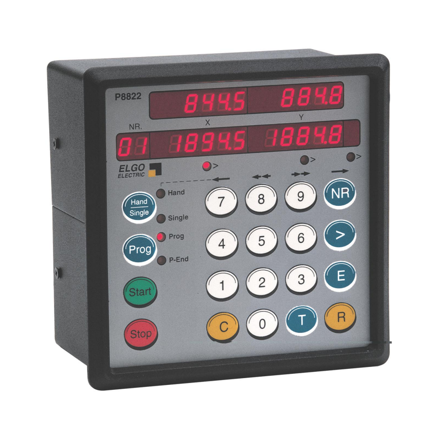
3. Front view/control elements P8822 ELGO > > > ELECTRIC Hand Hand Single Single Prog > Prog P-End Start Stop 3.1 Function of the displays Actual value : shows the actual positions of the axes Target value : preset window for the target positions shows the number of the selected program line LED Hand shines if the button Hand/Single is pressed for 2 times... - Page 7 NR – This key is only active in the Prog- Mode ( Prog must be pressed before and the LED Prog must shine) and has the following functions: 1. Begin of the program memory entry (after this, use > - Button to step up) 2.
-
Page 8: Controller In Operation
4. Controller in Operation Switch on conditions: On switch on, the controller assumes the same conditions as at the switch off time. The actual position is memorized. - In Hand- and Prog- Mode , the target windows are set to zero - In Single- Mode the old target values (before power off) are present 4.1 Single operation Additional to program operation, a single line for X and Y axes can be operated. - Page 9 4.2.2 Enter a program The required program block is selected in accordance with section 4.2.1. First step - Target value X Please press NR 01 appears in the Nr. window The LED under target window X shines Now press Clears the target value – X , the display shows „0“ Use the keys 0…...
-
Page 10: Manual Inching
4.4 Manual inching Press T to reset all target windows to zero Hand/Single to activate Hand mode the appropriate LED shines The buttons 7 / 8 / 9 / NR can be used to move the axis forward and backwards at high and low speeds (whilst the button is depressed). -
Page 11: Setting And Changing Register Values
5.2 Setting and Changing Register Values Example: A slowdown point of 20.0 mm needs to be entered. Assuming that registers have been unlocked as above : Press R The Nr. window flashes . Press 1 1 flashes in Nr. window i.e. Register 01. Press >... -
Page 12: Register Table (Parameter)
6. Register table (Parameter) Registers, signed as * can be changed without the security code R98. Register Function Unit X- Axis Y- Axis Slow speed distance 0.1 mm Creep speed distance 0.1 mm Correction stop (stop offset) 0.1 mm Backlash compensation 0.1 mm Retract distance 0.1 mm... -
Page 13: Description Of Registers
7. Description of Registers R01 - Slow speed distance X/Y Distance to the target position at which the controller switches from high speed to slow speed. The output high speed will be switched off. R02 - Creep speed distance X/Y Distance to the target position at which the controller switches from slow to creep speed R03 - Stop offset distance X/Y The over run distance can be programmed to compensate for distance from the switch-... -
Page 14: R8 System Register
R8 System Register 1 Target value windows X and Y Backlash compensation 0 = Without backlash compensation 1 = With negative backlash compensation 2 = With positive backlash compensation Relay output configuration 0 = 2 speeds, independent outputs for speed and direction 1 = 2 speeds, independent outputs for speed, additional reverse 2 = 2 speeds, separate outputs for each condition 3 = 3 speeds, additional reverse output... - Page 15 Drive control output configuration (Relays) R8/5 = 0 2 speeds, independent outputs for speed and direction Output signals ST4=X/ST6=Y Creep forwards Slow forwards Fast forwards Creep reverse Slow reverse Fast reverse X = output activated R8/5 = 1 2 speeds, independent outputs for speed and additional reverse signal Output signals ST4=X/ST6=Y Creep forwards Slow forwards...
- Page 16 R8/5 = 5 2 speeds, independent speed and direction outputs, separate reverse output Output signals ST4=X/ST6=Y Creep forwards Slow forwards Fast forwards Creep reverse Slow reverse Fast reverse X = output activated R8/5 = 6 2 speeds, additional reverse output, separate outputs for speed Output signals ST4=X/ST6=Y Creep forwards Slow forwards...
- Page 17 R9 - Time “in position” At the end of each move, the controller gives an output, to signal “in position” as long as the time register R9/X resp. R9/Y is. The length of this pulse is adjustable in R9 (range: 0.1… 9.9 s). Setting 0.0 gives a maintained output. R10 - Backlash dwell time When the machine stops at the end of the overrun, it is usually desirable to have a short delay.
-
Page 18: R18 System Register
R18 System Register 2 Target value windows X and Y Option Keyboard interlock 0 = Programming enabled 1 = Programming disabled 2 = All keyboard functions disabled 3 = Memory and START/STOP disabled Positioning in Prog 0 = Absolute 1 = Incremental + 2 = Incremental - Positioning in single 0 = Absolute... - Page 19 R29 Time delay for drive inhibit (positioning) On activating start, output positioning is activated. On arriving in position, after a time delay of R29 this output deactivates. R30 Time of “program end” signal If last step of a program is completed, the output signal program-end is activated for the time programmed in this register.
-
Page 20: R88 System Register
R88 System Register 4 Target value window X Incremental error comp 0 = not active 1 = active Output / Input Version 0 = D-Sub connector 1 = Relays output / Ria type input Double start at Prog end 0 = without 1 = with Address Line switching 0 = at position reached... -
Page 21: Function Of Inputs (St3 Connections)
8. Function of inputs (ST3 connections) ST 3 Pin 1 System reset The controller resets to home position ST 3 Pin 2 External START input for X-Axis The START input is an edge triggered input With activating, the X-Axis starts positioning ST 3 Pin 3 External START input for Y-Axis The START input is an edge triggered input With activating, the Y-Axis starts positioning... - Page 22 ST 3 Pin 15 NC ST 3 Pin 16 Program cycle counter – switches actual values into the display With activating ST3 Pin 6 , the counter value of the program cycle counter is displayed in the actual value windows: Actual value X = Counter value Actual value X = Counter value ST 3 Pin 17 NC...
-
Page 23: Functions Of The Outputs (St4 / St6 Connections)
9. Functions of the outputs (ST4 / ST6 connections) ST 5 Pin 1-4 drive control output of X axis These outputs are differently configurable in register R8/5 X ST 5 Pin 5-8 drive control output of Y axis These outputs are differently configurable in register R8/5 Y ST 5 Pin 14 position reached X pulse After positioning of the X axis, the output pulses according to the time adjusted in R9/X . - Page 24 10. Rear of the unit OUTPUTS ST5 Power Supply Fuse 0,4 A RS-232 INPUTS ST3 Encoder X Encoder Y...
-
Page 25: Connections
11. Connections ST 4 Relay control outputs for X Axis Conf. 3 Conf. 7 (LD) Conf. 8 (AD) Conf. 9 (DR) Relay 1 - 2 Axes in position Axes in position Axes in position Axes in position 3 – 4 Slow forwards Forwards Forwards... -
Page 26: Technical Specifications
12. Technical specifications Function Data Power supply +24 VDC (e.g. with ext. power pack NG 13.0) 230V/115V AC +/- 10 % Note: Please don’t exceed the max. load of 600 mA (max. available with NG 13.0,) when connecting the equipment, inclusive connected encoders and loaded resp. activated output signals. -
Page 27: Installation And Wiring
Attention! To ensure a perfect function of the controller P8822 the following installation guide-lines must be strictly observed and followed. Otherwise the guarantee expires and ELGO Electric GmbH takes no liability and guarantee for malfunctions or damages caused e.g. by incorrect installed wires or other external sources of error or interference, which are exactly explained below. -
Page 28: Only For Service
14. Only for Service Service Register 90 How to access the service register? At first the security code in R98 must be used and the service enable must be activated R90 . With entering the service register R90, the following functions are selectable: R 90 = 000001 Load customer adjustment (Register R88/2 adjustment) R 90 = 000002... -
Page 29: Liability Exclusion / Guarantee
The guarantee period is one calendar year from the date of delivery and includes the deliv- ered unit with all components. ELGO Electric GmbH will at its option replace or repair without charge defects at the unit or the included parts, verifiable caused by faulty manufacturing and/or material in spite of proper handling and compliance to the instruction manual.
Need help?
Do you have a question about the P8822-000-R Series and is the answer not in the manual?
Questions and answers