Table of Contents
Advertisement
Quick Links
Advertisement
Table of Contents

Related Manuals for BAYTEK GAMES PERFECTION

Summary of Contents for BAYTEK GAMES PERFECTION
- Page 1 SERVICE MANUAL...
-
Page 2: Factory Contact Information
FACTORY CONTACT INFORMATION BAY TEK GAMES INC. Pulaski Industrial Park 1077 East. Glenbrook Drive Pulaski, WI 54162 USA JOIN OUR SERVICE FIRST NETWORK! This free service is intended to keep you up to date on the latest game information, early notification of parts specials, pertinent technical bulle- tins, updates on retro fit parts, software upgrades, and much more. -
Page 3: Table Of Contents
WELCOME TO: Perfection ........ -
Page 4: Welcome To: Perfection
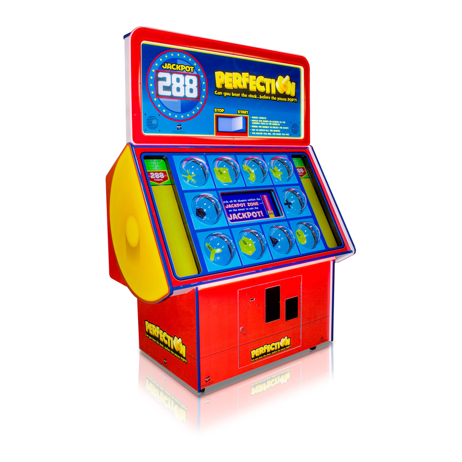
WELCOME TO: Perfection Congratulations on your Perfection purchase! The classic Hasbro board game Perfection has been a family favorite for generations— and now it’s supersized for your FEC! A great game of speed, dexterity and matching skill, Perfection can be played alone or as a family. Let’s get poppin’! Please take a moment to read through this manual and be sure to contact our factory if you have any questions, or would like some more information. -
Page 5: How To Play
HOW TO PLAY Hit the bubble containing the hole that matches the shape on the screen. The more you match, the more tickets you win! Match all 10 shapes before the Jackpot Timer runs out to win big! -
Page 6: Specifications
GAME SPECIFICATIONS WEIGHT POWER REQUIREMENTS NET WEIGHT 490 LBS. INPUT VOLTAGE 100 to 120 220 to 240 RANGE SHIP WEIGHT 550 LBS. INPUT FREQUENCY DIMENSIONS 50 HZ 60 HZ RANGE WIDTH 63” MAX OPERATING DEPTH 34” CURRENT HEIGHT 89” 3.2 AMPS @ 115 VAC OPERATING TEMPERATURE 1.8 AMPS @ 230 VAC FAHRENHEIT... -
Page 7: Marquee Setup
MARQUEE SETUP Unpack the game and marquee from the shipping pallet. Locate the marquee hardware packet inside the cashbox. Buddy-lift the marquee up into place, and route the cables down through the hole as shown. Lift the marquee and insert the tabs in the slots, allowing it to lock into place, and making sure the cables don’t get pinched. - Page 8 MARQUEE SETUP Secure the marquee with the included hardware and a 9/16” ratchet or driver bit. Open the lower back door to access the wiring connections. Plug the ribbon cable into the auxiliary board as shown.
- Page 9 Neatly clip the cables into the wire saddles and close up the game. Plug the game into a standard electrical outlet and turn the power strip to ON. It’s PERFECTION!
-
Page 10: Marquee Update Instructions
MARQUEE UPDATE INSTRUCTIONS Marquee Update Instructions The Marquee for Perfection has been improved with more attraction lighting and improved graphics. These instructions will provide show how to swap the older marquee to this newer marquee. Tools Needed: Game keys 7/16” Socket Instructions: 1.) Unplug game from the wall. - Page 11 MARQUEE UPDATE INSTRUCTIONS 7.) Locate the 5 cables in the new Marquee and push them down through the hole into the lower cabinet. 8.) Connect these cables into the cabinet wiring as: 8708 cable to 9731 cable 9709 ribbon cable to the splitter board 9707 cable to a power supply connector 9705 cable to the Newgen speaker socket 9737 cable to the J22 socket on the Newgen Board.
-
Page 12: Main Menu Functions
MAIN MENU Press the MENU button inside the front door of the cabinet to enter the game menu. The menu will appear on the center playfield. Scroll through the menu options with the MENU button. Make your selections with the MENU SELECT button. -
Page 13: Volume Settings
VOLUME SETTINGS FACTORY DEFAULTS ARE HIGHLIGHTED BELOW ATTRACT VOLUME GAME VOLUME JACKPOT VOLUME ATTRACT TIMING ALWAYS ON (IN MINUTES) GAME SETTINGS FACTORY DEFAULTS ARE HIGHLIGHTED BELOW NORMAL / NORMAL / ENTERTAINMENT GAME SETTINGS SHOW MODE TICKETS POINTS ONLY PENALTY TIME (IN MILLISECONDS) GAME TIME -TO-... -
Page 14: Payout Settings
PAYOUT SETTINGS FACTORY DEFAULTS ARE HIGHLIGHTED BELOW CREDITS PER PLAY SWIPE PROMPT ENABLED DISABLED PAPER TICKET VALUE FIXED TICKETS ENABLED DISABLED PROGRESSIVE INCREMENT VALUE OF JACKPOT INCREASES BY THIS NUMBER PER GAME PLAYED -TO- JACKPOT START 1000 DEFAULT: 500 INCREMENTS OF 5 -TO- JACKPOT MAXIMUM... -
Page 15: Statistics
STATISTICS TOTAL GAMES PLAYED GAMES PLAYED SINCE LAST TIME STATISTICS WERE CLEARED TOTAL TICKETS TOTAL NUMBER OF TICKETS DISPENSED JACKPOT WINNERS TOTAL NUMBER OF JACKPOT WINNERS SINCE LAST STATISTIC CLEARING AVERAGE TICKETS TOTAL AVERAGE NUMBER OF TICKETS DISPENSED CLEAR STATISTICS HIT MENU SELECT 3 TIMES TO CLEAR STATISTICS DIAGNOSTICS THE DIAGNOSTICS MENU DISPLAYS THE STATUS OF ALL INPUTS... -
Page 16: Wiring Diagrams
WIRING DIAGRAMS Circuit Board Wiring AANEWGEN1-PJ/RBN AACE9712 AACE9704 Comm to Switch Inputs Control Board AACE9704 AACE9714 Coin Door Menu Buttons AACE9704 Ticket Dispenser AACE9710 Bill Acceptor AACE9737 Marquee Front Lighting AANEWGEN1-PJ/RBN USB Socket to Update Software AACE9726 AACE9700 Ribbon Cable to Low Ticket Switch Splitter Board AACE9705... - Page 17 WIRING DIAGRAMS AC In & Power Supply Wiring Diagram AC IN & POWER SUPPLY To Marquee - Refer to Marquee Wiring Diagram Lower Front A5MO0065 AACE9707 AACE9708 To Marquee Plastic LED Monitor 5 VDC to Display Back Lighting lighting AACB9509 Games under serial #180 may have this board...
- Page 18 WIRING DIAGRAMS Marquee Wiring Diagram MARQUEE AACE9738 AACE9738 AACE9738 AACE9738 LED Light LED Light LED Light LED Light Display Board (Viewed from back) A5LD1052 AACE9728 Display Marquee Yellow LED’s AACE9718 AACE9737 Marquee Front Lighting AACE9719 AACE9709 Bottom Cabinet AACE9707 5 VDC to Display AACB6401 AACE9737 Marquee Front Lighting...
- Page 19 WIRING DIAGRAMS COIN MECH, TICKET DISPENSER, LOW TICKET SWITCH AACBL4A-DOOR AACE9704 Coin Switches and Lights From J21 Connector AACE9704 Ticket Dispenser To J6 on Part # A5TD1 Newgen 12 Volt Power Enable Signal AACE9704 AACE9704 Com Ground Notch Signal To J5 on Newgen AANEWGEN1-PJ/RBN AACE9700 AACE9700...
- Page 20 WIRING DIAGRAMS SPEAKER, MENU BUTTONS, COUNTERS, BILL ACCEPTOR 2 Blank plates for Bill Acceptor Hole are part #’s A5PL4200 & A5PL8900 To Bill Acceptor Part # A5AC9091 AACE9710 AACE9710 To J8 on Newgen AACE9714 To J25 on Newgen AACE9714 AANEWGEN1-PJ/RBN AAPB2700 AAPB2700 AACO3325...
- Page 21 WIRING DIAGRAMS BUTTON PANEL SWITCH View of playfield as it is opened Top of Playfield Game Cabinet AACE9702 To top row of Switches AACE9704 AACE9703 To center row AADO9700 To Coin of Switches Bubble Dome Door Cable 10 per game AACE9701 Pink &...
- Page 22 WIRING DIAGRAMS COMMUNICATION A5MO0065 Monitor A5CORD36 HDMI cable from motherboard to HDMI 1 on the TV AAMB9A-HD Motherboard AANEWGEN1-PJ/RBN A5CN1031 A5CEAU010 Adaptor Audio Jack from green socket on Motherboard to NewGen AACE9713 AACE9712 Communication cable from J2 on Interface Board to Motherboard Communication cable from blue J16 on Newgen board to J1 on Interface Board.
-
Page 23: Troubleshooting Guide
TROUBLESHOOTING GUIDE Troubleshooting Guide Problem Probable Cause Remedy Unplugged. Check wall outlet cable (A5CORD5) to line filter in back of game. (A5FI9010) and cable AACE9715 No power to the Power strip turned off, Check rocker switch on power strip. (AACE9716) Insure game. - Page 24 TROUBLESHOOTING GUIDE Problem Probable Cause Remedy Volume too low. Check by pressing Menu button, and ensure “Mute Option” is disabled. Enter the “Volume & Attract Settings” and adjust volume levels. Loose wire. Check audio cable connections from motherboard to I/O board to speakers (A5CEAU010, AANEWGEN1-PJ/RBN, AACE9705, AACE8811) Audio ...
- Page 25 TROUBLESHOOTING GUIDE Troubleshooting Guide Problem Probable Cause Remedy Monitor HDMI cable unplugged. Check the connection at the cable Monitor shows to the monitor. (A5CORD36) “No Signal” Verify it is plugged into HDMI 1 port. The Motherboard is not telling the power supply to turn on. Refer to “Motherboard and Power Supply Diagnostics”...
- Page 26 Troubleshooting Guide TROUBLESHOOTING GUIDE Problem Probable Cause Remedy Game turns on, but None of inputs work. No coin Phone communication cable unplugged or faulty some of the functions up, no test buttons, display from NewGen board to motherboard. do not work. may say communication error.
- Page 27 TROUBLESHOOTING GUIDE Problem Probable Cause Remedy Verify game is registering a Display monitor will show ticket value won. win. If not – check menu settings. Tickets not dispensing Notch on tickets too shallow. Flip tickets and load upside-down to have large cut notch toward opto sensor.
- Page 28 Game or Monitor Does Not Turn On TROUBLESHOOTING GUIDE Important: Monitor must be ON, or motherboard will not even try to boot. To troubleshoot: the monitor should show “No Signal” , then turn the power supply on to allow the motherboard to boot up.
-
Page 29: Diagnostics
DIAGNOSTICS BUTTON DOME SWITCH Game play matching is activated by a magnetic switch in the dome button. There is a special magnet attached to each plastic dome, and a receiver mounted to the housing. The switch is activated when the magnet comes in close proximity to the receiver. If one button is stuck down, after 30 seconds the game will show this error message under the button. - Page 30 DIAGNOSTICS MOTHERBOARD & POWER SUPPLY 1.) Verify AC power to game. Check power strip in front door. The rocker switch should be illuminated. 2.) Check connection to power supply. 3.) Ensure Power Supply switch is set to 115V (or 230V) (Some model power supplies may not have this) 4.) Ensure Power switch is on.
- Page 31 DIAGNOSTICS BILL ACCEPTOR Note: There are many different models and brands of Bill Acceptors that are used on redemption games. Your Bill Acceptor may differ from the unit shown. Standard DBA is MEI # AE2451-U5E Part # A5AC9091 Note: If Bill Acceptor is not used, there are 2 blanking plates to be installed to cover the hole in the front door.
-
Page 32: Card Setup Instructions
CARD SET UP INSTRUCTIONS The Perfection game is pre-wired with a UCL (Universal Card Link) connector to accept Card Swipe systems from many different manufactures. Please follow these instructions to make full use of Perfection’s capabilities. Option #1: Card swipe systems may come with a standard 9 pin Molex connector. -
Page 33: How To
HOW TO UPDATE SOFTWARE There are 2 boards into which software could be installed, depending on the circumstance: 1.) Newgen Software Installation - With game power ON - insert USB update stick into Minigen socket on left edge of board. Press “Boot”... -
Page 34: Access Button Panel Switches
HOW TO ACCESS MONITOR, BUTTONS, & SWITCHES FOR CLEANING Remove the 14 bolts (Phillips Bit) from the front plexi of the game. Remove plexi and remove the 3 screws (# 2 square bit) from left and right black plastic sides covering monitor. Tilt button panel forward. -
Page 35: Remove/Replace Monitor
HOW TO REMOVE BUTTON PANEL AND MONITOR Open back door and set aside. Unclip the CE9703 & CE9701 cables from the wire saddles and unplug the connectors to allow cables to be pulled out the front of cabinet. Unplug the CE9702 connector. These 3 cables will pull out the front of the cabinet along with the monitor. - Page 36 HOW TO REMOVE BUTTON PANEL AND MONITOR To remove monitor: Remove the 4 screws in the wood on both left and right sides of the cabi- net. Unplug the power cable and HDMI cable from the back of the monitor. Caution: 2 people are required for the next steps.
-
Page 37: Pinout
PINOUT AANEWGEN1-PJ/RBN... -
Page 38: Pin Descriptions
PIN DESCRIPTIONS Pin Type Purpose Pin Type Purpose Ref Pin # Ref Pin # LOWSIDE #1,w diode Ground J24 1 LOWSIDE #2, w diode Ground Ground for Low Ticket Switch J24 2 LOWSIDE #3 +12 Volts J24 3 LOWSIDE #4 +12 Volts J24 4 LOWSIDE #5... -
Page 39: Parts List
Decal, Cabinet Left Side AACE9714 Cable Assy, Menu/Counters A5DE9702 Decal, Cabinet Right Side AACE9715 Cable Assy, Line Filter Powercord1&2 A5DE9703 Decal, Perfection Marquee Face AACE9716 Cable Assy, Outlet Strip A5DE9704 Decal, Perfection Marquee Border AACE9717 Cable Assy, PS Ground To Main Bd A5DE9705... -
Page 40: Parts Pictures
PARTS PICTURES A5CORD5 A5BK9999 A5CA1005 A5CB2050 A5CE2300 A5CEAU010 A5CN1031 A5CORD36 W5HG1045 W5HG1065 W5HG1025 A5FI9010 A5ME2035 A5KE5000 A5LK2001 A5LK5002 W5TM4002 AACE7900 AACE9701 AACE9702 AACE9703 AACE9704 A5LD1052 AACE9710 AACE9711 AACE9714 AACE9715 AACE9716 A5PL4200 AACE9717 AACE9722 AACE9723 AACE9724 AACE9725 A5PL8900 A5PS1011 A5TD1 AACBL4A‐DOORA AACE8811 AASW200 AACO3325 AAMB9A‐HD AAPB2700 AACB2204A AACB3904 AANEWGEN1‐PJ/RBN ... -
Page 41: Decal Diagram
DECAL DIAGRAM Decal Diagram... -
Page 42: Maintenance Log
MAINTENANCE LOG If repairs are necessary, it is good practice to keep a log of repairs done and parts ordered. The chart below will assist you in tracking your game’s maintenance. DATE MAINTENANCE PERFORMED PARTS ORDERED INITIALS... -
Page 43: Technical Support
TECHNICAL SUPPORT Excellent customer service is very important to Bay Tek Games! We know that keeping your games in great operating condition is important to your business. When you need us, we are here to help. You can call us for free technical assistance, and you can count on us to have parts on-hand to support your game. -
Page 44: Warranty
WARRANTY Bay Tek Games warrants to the original purchaser that all game components will be free of defects in workmanship and materials for a period of 6 months from the date of purchase. If you fill out the registration card in the cashbox of the game, Bay Tek will add another 3 months to your warranty, free of charge.
Need help?
Do you have a question about the PERFECTION and is the answer not in the manual?
Questions and answers