Table of Contents
Advertisement
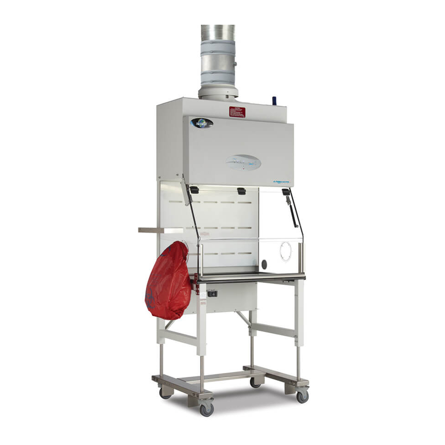
LabGard® Containment Ventilated Enclosure
Model
NU-813-300/400/600
NU-813-300E/400E/600E
Portable Bench Top
Operation & Maintenance Manual
February, 2019
Series 33
Revision 9
Manufactured By:
NuAire, Inc.
2100 Fernbrook Lane
Plymouth, MN 55447
Toll-Free: 1-800-328-3352
In Minnesota: (763)-553-1270
Fax: (763)-553-0459
OM0236
Page 1 of 52
Advertisement
Table of Contents

Related Manuals for NuAire LabGard NU-813-300


Summary of Contents for NuAire LabGard NU-813-300
- Page 1 LabGard® Containment Ventilated Enclosure Model NU-813-300/400/600 NU-813-300E/400E/600E Portable Bench Top Operation & Maintenance Manual February, 2019 Series 33 Revision 9 Manufactured By: NuAire, Inc. 2100 Fernbrook Lane Plymouth, MN 55447 Toll-Free: 1-800-328-3352 In Minnesota: (763)-553-1270 Fax: (763)-553-0459 OM0236 Page 1 of 52...
- Page 2 A copy of the original factory test report is also appended to this manual. In case this manual and/or test report is lost or misplaced, NuAire retains a copy in our files.
-
Page 3: Table Of Contents
LabGard® Containment Ventilated Enclosure Models NU-813-300/400/600 NU-813-300E/400E/600E Operation & Maintenance Manual TABLE OF CONTENTS Section No. 1 ........... General Information Section No. 2 ........... Models & Features Section No. 3 ........... Warranty Section No. 4 ........... Shipments Section No. 5 ........... Installation Instructions 5.1 ............ - Page 4 Keep these operating instructions close to the unit so that safety instructions and important information are • always accessible. • Should you encounter problems that are not detailed adequately in the operating instructions, please contact your NuAire Representative or NuAire Technical Service. OM0236 Page 4 of 52 February/2019...
- Page 5 1.3 Explanation of Symbols WARNING indicated a potentially hazardous WARNING Situation which, if not avoided, could result in WARNING Death or serious injury. CAUTION indicates a potentially hazardous CAUTION Situation which, if not avoided, may result in CAUTION Minor or moderate injury. CAUTION used without the safety alert symbol Indicates a potentially hazardous situation which, CAUTION...
- Page 6 OM0236 Page 6 of 52 February/2019...
- Page 7 2.0 Models & Features The NU-813 comes in three standard size widths: 36" (914mm) (Model-300/300E) 48" (1219mm) (Model-400/400E) 72” (1829mm) (Model-600/600E) OM0236 Page 7 of 52 February/2019...
- Page 8 OM0236 Page 8 of 52 February/2019...
- Page 9 OM0236 Page 9 of 52 February/2019...
- Page 10 OM0236 Page 10 of 52 February/2019...
- Page 11 However, damage can occur in any shipment and the following outlines the steps you should take on receipt of a NuAire LabGard® CVE to be sure that if damage has occurred, the proper claims and actions are taken immediately.
-
Page 12: Electrical Services
5.0 Installation Instructions 5.1 Location Within the laboratory, pharmacy, etc., the ideal location of the CVE is away from personnel traffic lanes, air vents (in or out), doors and/or any other source of disruptive air currents. If drafts or other disruptive air currents exceed the intake velocity of the cabinet through the access opening, the potential exists for contaminated air to exit the cabinet. -
Page 13: Certification Testing Methods And Equipment
5.4 Certification Testing Methods and Equipment After installation and prior to use, NuAire recommends that the CVE be certified or commissioned to factory standards. At a minimum, the following tests should be performed. 1. HEPA filter leak test 2. Inflow velocity test 3. - Page 14 LabGard® Containment Ventilated Enclosure Models NU-813-300/400/600/E Catalog Number Catalog Number NU-813-300/E NU-813-400/E NU-813-600/E Nominal 3 foot (0.9m) Nominal 4 foot (1.2m) Nominal 6 foot (1.5m) Performance Specifications ANSI/ASHRAE 110 ANSI/ASHRAE 110 ANSI/ASHRAE 110 1. Personal Protection NSF/ANSI 49 NSF/ANSI 49 NSF/ANSI 49 2.
- Page 15 6.0 Operating the NU-813 6.1 Aeromax™ Control System 6.1.1 Overview The Aeromax™ control system is designed to service the control requirements of the LabGard® ES NU-813 CVE. The Aeromax™ control system consists of an electronic module that will perform the following functions: •...
- Page 16 OM0236 Page 16 of 52 February/2019...
- Page 17 6.1.2 Front Panel The control system front panel contains the following functions described in detail (see Drawing BCD-16521). 6.1.2.1 Blower Keys The blower key controls the ON/OFF power to the blower. LED above key indicates: full green for blower on, blinking green for blower pending and full red for blower alarm.
- Page 18 6.1.5 Run Mode Any time the blower run key is pressed with the hinged window at its correct operational height, the RUN MODE screen will be initiated. The Run Mode will start with the PresurFlow™ entering and approximate 3 minute warm up period.
- Page 19 6.1.8 Operator Accessible Functions 6.1.8.1 Access and Navigation To access the operator accessible functions, • Press and hold the key, then enter the 3 key sequence for the desired function, then release key and follow each instruction set. Note: Pressing the key at any time will abort and exit the process without saving any changes made.
- Page 20 6.1.8.3 Blower Password The blower on/off password allows the cabinet user to place a 3 key sequence requirement to turn the blower on or off. The 3 key sequence for the blower password will be a combination of the hidden and blower keys. Select blower password •...
-
Page 21: Operating Guidelines
6.2 Operating Guidelines 6.2.1 The intent herein is to present general operating guidelines that will aid in the use of the CVE to control airborne contaminants of low to moderate risk. 6.2.2 Procedure protocols defined in terms of the barrier of control concepts unique to the CVE must be developed in order to obtain a maximum potential for safety and protection. - Page 22 6.2.6 Operating Sequence Start Up - Turn on CVE blower and lights, check air intake and exhaust portals of the unit to make sure they are unobstructed. Blower speed must only be readjusted by qualified maintenance technicians. Allow blowers to operate for a minimum of 5 minutes before manipulations are begun in the CVE. If the filtered air exhausted from the unit is discharged into the room, as in some installations, an additional advantage is obtained from purification (filtration) of characteristic contributing to the quality of the laboratory environment, some owners of CVE leave them in operation beyond the time of actual use.
-
Page 23: Ergonomics
NOTE: NuAire does not offer any product warranty with respect to cleaning material compatibility. USE AT YOUR OWN RISK! The information provided above is from raw material suppliers and known general source documents for use to develop application cleaning SOP’s. - Page 24 6.4.2 Panel Removal for Powder Use If the enclosure is used to contain powdered materials, periodically the work zone panels should be removed and cleaned. Use the following procedure for panel removal. When removing contaminated interior panels, continue to operate the enclosures blower to maintain negative pressure.
-
Page 25: Decontamination
General Maintenance All maintenance actions on this equipment must be performed by a qualified CAUTION technician who is familiar with the proper maintenance procedures required including both certification and repair. 7.1 Decontamination No maintenance should be performed on the interior of the LabGard® CVE (area behind access panels) unless the cabinet has been microbiologically decontaminated, is known to be biologically clean, or known to be chemically inert. -
Page 26: Fluorescent Lamp Bulb Replacement
2. Remove exhaust filter cover and follow bag-in/bag-out procedure per drawing BCD-15639 for removal and replacement. 3. Reverse above steps to complete the replacement process. 4: Filter Installation When installing new filters, USE ONLY NUAIRE SPECFIED FILTERS FOR REPLACEMENT. Description: Exhaust HEPA Filter (Single) Exhaust HEPA Filter (Dual) Efficiency: 99.995% @ 0.3 Micron... -
Page 27: Motor/Blower Replacement
7.4 Motor/Blower Replacement 7.4.1 The Motor/Blower assembly should never need any preventative maintenance. But in case of a malfunction, the following steps should be taken. Make sure unit is decontaminated before doing any repairs on the interior of the unit. Disconnect power or unplug unit before working with any electrical wiring. Motor/Blower removal should be done by a qualified technician. - Page 28 OM0236 Page 28 of 52 February/2019...
- Page 29 7.5 Airflow Control System Setup and Calibration 7.5.1 General The operation of the NU-813 CVE requires that the setup and calibration procedures be performed in order to certify or commission for usage. The setup and calibration procedures performed ONLY BY THE CERTIFIER ensure that setpoints are verified and that the airflow monitor sensor is calibrated to the correct values.
-
Page 30: Airflow Calibration
The NU-813 Airflow Calibration consists of adjusting the airflow. THIS WORK SHOULD BE DONE ONLY BY A QUALIFIED TECHNICIAN WHO CAN MEASURE THE AIRFLOW WITH A SUITABLE VELOMETER. NuAire provides one adjustment to set the airflow within the cabinet. This is: PWM signal adjust via calibration parameter menu. - Page 31 7.5.3.1 Inflow Calibration Step 1: Measure the inflow velocity using the recommended procedure found in Table 7.0. If necessary, adjust to achieve the correct average inflow velocity within the stated range of 80 + 5 LFPM (.41 + 0.25 m/s). Step 2: If necessary, enter active blower speed adjustment.
- Page 32 Table 7.0 Recommended Measurement Methods for CVE Inflow A. Inflow/Velocity Measurement Instrument: Shortridge Flowhood ADM-870 or TSI 8355 Thermo anemometer. b. Procedure: The inflow velocity is measured by using a Direct Inflow Measurement (DIM) Instrument (i.e. Shortridge flowhood). The DIM Instrument can be used directly on the cabinet with NO CORRECTION FACTORS REQUIRED. The DIM Instrument should also be duct taped to the cabinet to prevent any sneak air paths from occurring.
- Page 33 7.5.3.2 PresurFlow™ Alarm Set Points The PresurFlow™ alarm setpoints are based on the calibration setpoint. Once the calibration setpoint is entered, based on a nominal inflow velocity of 80fpm (.41mls) the associated pressure sensor value is entered as the nominal pressure value. The high and low alarm setpoints are factory verified and set if needed at 60fpm (.30mls) and 100fpm (.51mls).
- Page 34 7.5.3.3 Low Flow Calibration (See Section 8.2.2 to Activate the Low Flow Function) The Nite Care mode is defaulted to operate the blower at approximately 600 rpm or a 14% duty cycle. However, if desired the Nite Care blower speed can be adjusted higher or lower by performing the following: •...
-
Page 35: Filter Integrity Check
7.6 Filter Integrity Check The filter must be scan tested before installation into the CVE. Once installed, an internal reference leak test can be performed to assure a proper installation was performed. Challenge aerosol (One Laskin Nozzle, PAO) should be supplied in the rear center of the workzone and the exhaust probed above the ring. -
Page 36: Main Control Board Description And Replacement
Main Control Board Description and Replacement To access the main control board for fuse or board replacement, remove screws at each upper side of the control center and allow the control center to rotate down, resting on the safety straps. Now the main control board is exposed for service. - Page 37 813 Dual HEPA Filter Testing The NU-813 (Series 30) with the double HEPA filter option requires additional HEPA filter integrity testing. The additional HEPA filter integrity tests are performed by accessing the ports behind the control box. THESE PORTS ARE UNDER POSITIVE PRESSURE, CAUTION SO ACCESS SHOULD ONLY BE MADE WITH THE BLOWER OFF.
- Page 38 A third test shall be performed to verify the integrity of the seal of the cabinet itself. The same internal reference is used. The challenge is introduced into the workzone and the exhaust airflow if probed. The leakage shall not exceed .005%. 8.0 Error Messages, Troubleshooting, Option-Diagnostics and Airflow Sensor Performance Verification Audible alarms and error messages occur for a variety of reasons.
- Page 39 8.2 Option Parameters The option parameter menu allows A QUALIFIED TECHNICIAN to configure several different optional parameters per the menu as described below. 8.2.1 Sync Function with Active Blower To access the option parameter menu, perform the following: • Press and hold key, then press hidden - Blower - Fluorescent keys sequentially.
- Page 40 • Pressing the key will abort the process and exit Require Password – Normally it is not required to use a password (i.e. 3 key press sequence of the blower and hidden key). If the option is turned on, it would be required to use the correct password to turn on the blower.
- Page 41 OM0236 Page 41 of 52 February/2019...
- Page 42 10.0 Remote Contacts The NU-813 has several contact closures for remote sensing of various functions. 10.1 Fan Relay The fan relay contacts are normally open and closed contact closure outputs that are activated whenever the blower key is pressed and the blower key LED indicator is on or blinking. Contact ratings are 250 VAC maximum at 2 Amps. 10.2 Alarm Relay The alarm relay contacts are normally open and closed contact closure outputs which are activated whenever an airflow alarm condition occurs.
- Page 43 11.0 Electrical/Environmental Requirements 11.1 Electrical (Supply voltage fluctuations not to exceed +/- 10%) NU-813-300/400/600 115Vac, 60Hz, 1 Phase, 5 Amps NU-813-300E/400E/600E 230Vac, 50/60Hz, 1 Phase, 3 Amps 11.2 Operational Performance (for indoor use only) Environment Temperature Range: 41°F-104°F (5°C - 40°C) Environment Humidity: Maximum relative humidity 80% for temperatures up to 31°C Decreasing linearly to 50% relative humidity at 40°C...
- Page 44 12.0 Disposal and Recycle CVE’s that are no longer in use and are ready for disposal contain reusable materials. ALL components with the exception of the HEPA filters may be disposed and/or recycled after they are known to be properly disinfected. ...
- Page 45 OM0236 Page 45 of 52 February/2019...
- Page 46 OM0236 Page 46 of 52 February/2019...
- Page 47 OM0236 Page 47 of 52 February/2019...
- Page 48 OM0236 Page 48 of 52 February/2019...
- Page 49 OM0236 Page 49 of 52 February/2019...
- Page 50 OM0236 Page 50 of 52 February/2019...
- Page 51 OM0236 Page 51 of 52 February/2019...
- Page 52 OM0236 Page 52 of 52 February/2019...
Need help?
Do you have a question about the LabGard NU-813-300 and is the answer not in the manual?
Questions and answers