
Related Manuals for ARAG 463 Series


Summary of Contents for ARAG 463 Series
- Page 1 PROPORTIONAL CONTROL UNIT FOR ORCHARD SPRAYER APPLICATIONS SERIE 463 - 465 INSTALLATION, USE AND MAINTENANCE...
-
Page 2: Legend Symbols
This manual is an integral part of the equipment to which it refers and must accompany the equipment in case of sale or change of ownership. Keep it for future reference; ARAG reserves the right to modify the specifications and instructions regarding the product at any time and without prior notice. -
Page 3: Table Of Contents
CONTENTS • Legend symbols.......................2 1 Product description ......................4 Intended use ......................4 2 Functioning of the product .....................5 Composition of proportional control units ..............5 Functions of components ..................6 3 Installation ........................7 Safety regulations ....................7 Installing and connecting the unit ................7 Connecting up the system ..................9 Connection to control devices ................ -
Page 4: Product Description
For detailed information, please refer to the description of the part in question and not of the unit in general. ARAG is not liable for direct or indirect damage due to the type of product used for treatment with its control units. -
Page 5: Functioning Of The Product
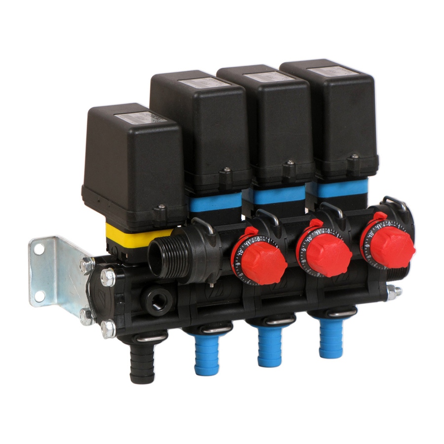
FUNCTIONING OF THE PRODUCT Composition of proportional control units Fig. 1 Maximum pressure valve Proportional electric valve Proportional valve Discharge valve Filter Boom section electric valves Metered by-passes Pressure gauge adapter or pressure transducer connection Intake of liquid for spraying Outlet for the maximum pressure valve, proportional valve and discharge valve OUT A Outlet for metered by-pass... -
Page 6: Functions Of Components
Functions of components Maximum pressure valve Eliminates the excess liquid when the set pressure level is reached. Can be adjusted manually using the appropriate knob; the knob has a different colour according to the maximum pressure for the valve (refer to par. 7.1 - Correspondence between valve parts and maximum valve pressure). -
Page 7: Installation
Have the unit installed by qualified personnel. ARAG is not liable for any damage to equipment or injury to persons, animals or things caused by incorrect or unsuitable connection of the unit. Likewise, ARAG is not liable for any damage caused directly or indirectly to equipment or machinery, or injury to persons, animals or things caused by unsuita- ble or unfit hoses, cable grips, wraps or other accessory. - Page 8 Observe unit mounting positions shown in Fig. 3. STANDARD MOUNTING POSITION Fig. 3...
-
Page 9: Connecting Up The System
Connecting up the system Connect the hoses in the system according to the layout shown below. Take care: - Not to connect backflow hoses in the lower part of the tank with the intention of using them as hydraulic stirrers; only place them in the upper part so the liquid drops down by gravity, as shown in Fig. -
Page 10: Connection To Control Devices
; minimum required cross-section area for cables connected to remaining unit components is 0,75 mm • Any damage resulting from use of unsuitable cables or anyway other than ARAG cables will automatically invalidate any warranty rights. • ARAG disclaims all liabilities for damage to equipment, persons, animals or things... -
Page 11: Setting Before Use
• Pressure gauge: Screw into pressure gauge adapter seat until firmly in place; do not overtighten. Use ARAG pressure gauges with 1/4" M coupling and a suitable end scale for the maximum operating pressure. • Pressure transducer: Use ARAG transducers (code 466112.x00); please read the instructions manual supplied with the device for full installation information. - Page 12 Turn the knob anticlockwise to completely open the hand wheel of the maximum pressure valve. Fully open the proportional valve: • manual proportional valve: turn the valve’s knob anticlockwise. • proportional electric valve: push the respective switch on the control unit down. Set the relevant switches on the control device to "OFF"...
-
Page 13: Adjustment Of Maximum Operating Pressure
Adjustment of maximum operating pressure Should either of the following be noted during operation: • pressure above the maximum limit for the system and safety valve; • abnormal leaks of liquid; - stop work, switch the pump off and check that the installation and preliminary procedu- res have been completed correctly. -
Page 14: Use
For detailed information on operation or adjustment of unit valves, ALWAYS refer to the operating and maintenance instructions manual relevant to your control device. Pressure readings are indicated by the pressure gauge or displayed at the control device (where unit is equipped with a pressure transducer). Calibration of operating pressure Select the type of nozzle and the relative operating pressure according to the litres/hectare (l/ha) to be sprayed and the speed of progress. -
Page 15: Calibrating The Metered By-Passes
Calibrating the metered by-passes These cocks safeguard the constant distribution of liquid even in case of operation with one or two section valves closed. Calibration must be carried out EACH TIME the type of nozzle is changed. The metered by-pass calibration knobs are equipped with a graduated scale. Once each metered by-pass has been calibrated, enter the value of the graduated scale for the type of nozzle in use in the tables on page 17. - Page 16 Calibrate ALL section valves before running a treatment; the calibration can be done as follows, depen- ding on the configuration of the control unit: • EQUAL section valves: you need only calibrate one single valve, then set the graduated scales of all the others to the same mark. •...
-
Page 17: Metered By-Pass Calibration Tables
5.2.1 Metered by-pass calibration tables NOZZLE NOZZLE NOZZLE COLOR REF. COLOR REF. COLOR REF. TYPE TYPE TYPE NOZZLE NOZZLE NOZZLE COLOR REF. COLOR REF. COLOR REF. TYPE TYPE TYPE NOZZLE NOZZLE NOZZLE COLOR REF. COLOR REF. COLOR REF. TYPE TYPE TYPE... -
Page 18: Maintenance / Diagnostics / Repairs
• Wait until unit is fully dry before restoring electric connections. • ARAG is not liable for any damage caused to equipment or injury to persons, ani- mals or things caused by cleaning with unsuitable products. All forms of warranty are rendered null and void in case of damage to the unit caused by the above. -
Page 19: Cleaning The Filters
Take care not to damage the mesh when cleaning the filter: should you notice any damage to the mesh, replace the cartridge with a new one. Refer to the ARAG spare parts catalogue for references for ordering spare parts. -
Page 20: Continuous Wash Filters
6.2.2 Continuous wash filters Before doing anything, make sure the filter’s discharge outlet is connected to the tank with a hose. The unit can be washed in the following two ways: • Continuous wash (recirculating): The filter cock is left open so that cleaning is carried out during spraying. To use the filter in this mode, check that the unit’s input flowrate is sufficient to feed both the unit and the filter outlet itself. - Page 21 Before doing anything, make sure the filter’s discharge outlet is connected to the tank with a hose. • Regular cleaning: This procedure can be carried out at the end of each use or any time it is deemed necessary: Protective gloves, goggles and clothing must be worn. Start the pump and take it to its operating level.
- Page 22 Allow the system to operate for at least 2 minutes. Open the discharge valve with the switch on the control unit (set to ON). Completely close the filter outlet by turning the tap clockwise. End of par. 6.2.2 - Continuous wash filters...
-
Page 23: Troubleshooting
Troubleshooting TROUBLE CAUSE REMEDY • Check the electrical connection: the cable marked “G” must be con- nected to the discharge valve (light The discharge valve’s motor is faulty blue or red collar). • Have gearmotor inspected at the nearest Service Centre. Inlet and outlet tubes not connected •... -
Page 24: Technical Data
TROUBLE CAUSE REMEDY Pressure gauge malfunctioning • Change pressure gauge. Squashed gasket inside pressure • Slightly loosen pressure gauge. Pressure gauge reading higher gauge is partially obstructing passage than actual pressure Passages across valve and nozzle • Choose section valve tubes and hose undersized, leading to significant tails of correct size. - Page 25 Notes...
-
Page 26: Guarantee Terms
GUARANTEE TERMS 1. ARAG s.r.l. guarantees this apparatus for a period of 360 day (1 year) from the date of sale to the client user (date of the goods delivery note). The components of the apparatus, that in the unappealable opinion of ARAG are faulty due to an original defect in the material or production process, will be repaired or replaced free of charge at the nearest Assistance Centre operating at the moment the request for intervention is made. - Page 27 CONFORMITY DECLARATION The declaration of conformity is available at www.aragnet.com, in the relevant section.
- Page 28 Only use genuine ARAG accessories or spare parts to make sure manufacturer guaranteed safety conditions are maintained in time. Always refer to the internet address www.aragnet.com 42048 RUBIERA (Reggio Emilia) - ITALY Via Palladio, 5/A Tel. 0522 622011 Fax 0522 628944 http://www.aragnet.com...
Need help?
Do you have a question about the 463 Series and is the answer not in the manual?
Questions and answers