Table of Contents
Advertisement
Advertisement
Table of Contents

Related Manuals for Chroma 19032-P


Summary of Contents for Chroma 19032-P
- Page 1 Electrical Safety Analyzer 19032-P Quick Start Guide...
- Page 3 Electrical Safety Analyzer 19032-P Quick Start Guide Version 1.5 February 2012 P/N A11 000208...
- Page 4 Legal Notices The information in this document is subject to change without notice. Chroma ATE INC. makes no warranty of any kind with regard to this manual, including, but not limited to, the implied warranties of merchantability and fitness for a particular purpose. Chroma ATE INC. shall...
- Page 5 All Chroma instruments are warranted against defects in material and workmanship for a period of one year after date of shipment. Chroma agrees to repair or replace any assembly or component found to be defective, under normal use during this period.
- Page 6 Material Contents Declaration The recycling label shown on the product indicates the Hazardous Substances contained in the product as the table listed below. : See <Table 1>. : See <Table 2>. <Table 1> Hazardous Substances Lead Mercury Cadmium Hexavalent Polybrominated Polybromodiphenyl Part Name Chromium...
- Page 7 “ ” indicates that the level of the specified chemical substance exceeds the threshold level specified in the standards of SJ/T-11363-2006 and EU 2005/618/EC. Chroma is not fully transitioned to lead-free solder assembly at this moment; however, most of the components used are RoHS compliant.
- Page 8 Failure to comply with these precautions or specific WARNINGS given elsewhere in this manual will violate safety standards of design, manufacture, and intended use of the instrument. Chroma assumes no liability for the customer’s failure to comply with these requirements. BEFORE APPLYING POWER Verify that the power is set to match the rated input of this power supply.
- Page 9 Safety Symbols DANGER – High voltage. Explanation: To avoid injury, death of personnel, or damage to the instrument, the operator must refer to an explanation in the instruction manual. High temperature: This symbol indicates the temperature is now higher than the acceptable range of human. Do not touch it to avoid any personal injury.
- Page 10 Save all packing materials in case that the instrument has to be returned. If damage is found, please file claim with carrier immediately. Do not return the instrument to Chroma without prior approval. Standard Accessory Item Q’ty...
- Page 11 The Danger of Operating 1. When the instrument is under output voltage, please don’t touch test area or you may shock hazard and result in death. Please obey the following items. • Make sure the grounding cable is connected correctly and using the standard power cord.
- Page 12 Remove all connected wires and cables on the instrument before cleaning. Use a brush gently to clean the dust on it. For internal cleaning, use a low-pressure air gun to vacuum the dust inside or send it back to the distributors or agents of Chroma for cleaning.
-
Page 13: Table Of Contents
Electrical Safety Analyzer 19032-P Quick Start Guide Table of Contents 1. Introduction ..................... 1 An Overview of Product ............1 2. Specification (18°C ∼ 28°C RH ≤ 70%) ..........2 3. Precaution before Use ................. 7 4. Description of Panel ................14 Front Panel ............... -
Page 15: Introduction
Electrical Safety Analyzer 19032-P Quick Start Guide Introduction An Overview of Product Automatic withstand / insulation / grounding testers of the instrument are designed for automatic withstand, insulation resistance, grounding resistance, short/open circuit detection and dynamic leakage current test of electromechanical and electronic equipments. -
Page 16: Specification (18°C ~ 28°C Rh ≤ 70%)
Electrical Safety Analyzer 19032-P Quick Start Guide 2. Specification (18°C ∼ 28°C RH ≤ 70%) AC/DC Withstanding Test AC: 0.05-5.0 kV, steps 0.001kV, DC: 0.05-6.0 Output Voltage kV, steps 0.001kV. ≤ (2% of setting + 0.1% of full scale), Rated... - Page 17 Electrical Safety Analyzer 19032-P Quick Start Guide AC: 1mA – 20mA, DC: 1mA – 10mA, resolution Detection Current 0.1mA Min. pulse width 40us 20us 10us 4us Approx. TwinportTM function (SPC) WV and GB test can be performed at the same Functions time.
- Page 18 Electrical Safety Analyzer 19032-P Quick Start Guide Current Resistance 10mΩ 100mΩ 510mΩ Limit Value Setting HI - LIMIT 0.1 ~ 510.0mΩ Offset Range 0 ~ 500.0mΩ Test Time(Note 6) 0.3 ~ 999 sec. Continue Secure Protection Function Ground Fault Interrupt AC:0.25mA~0.75mA, ON/OFF selectable...
- Page 19 Electrical Safety Analyzer 19032-P Quick Start Guide Remote Connector 9-Pins connector: Rear Panel START, RESET, UNDER TEST, PASS, FAIL Start/Reset Control TTL Low Level Active, minimum 20mS Baud rate 300 ∼ 19200, data bits: 8. stop bit: 1 RS232 Interface The programming language is SCPI.
- Page 20 Electrical Safety Analyzer 19032-P Quick Start Guide The current resolution is 1.2count for WAC, and 1.6count for WDC calculated value. The minimum testing time arrives at 90% output voltage specification(NO load). Design in Specifications. Validation point is 1.25kV with a 250kΩ...
-
Page 21: Precaution Before Use
Electrical Safety Analyzer 19032-P Quick Start Guide 3. Precaution before Use The analyzer is with high voltage output up to 6KV sending to external test. It may occur injury and death result from error operation. Please peruse notice item of this chapter and remember to avoid accident. - Page 22 Electrical Safety Analyzer 19032-P Quick Start Guide Connection test of high voltage output terminal After the test cable of HV2 terminal has been connected. Then follow the below procedures to connect high voltage output cable. • Press [STOP] key firstly.
- Page 23 Electrical Safety Analyzer 19032-P Quick Start Guide Please don’t touch here when outputs high voltage. Figure 3-3 <<< Warning ! When the output terminal is cut off >>> Test complete confirmation You may touch DUT, high voltage test cable or output terminal etc high voltage areas under modifying circuit or others test requested conditions.
- Page 24 Electrical Safety Analyzer 19032-P Quick Start Guide seconds. To assume the time constant of DUT is known, if you want to know the voltage decrease to below 30V needed time. Please follow the above procedures, multiply decrease to below 30V needed time-by-time constant.
- Page 25 Electrical Safety Analyzer 19032-P Quick Start Guide voltage. Please connect the cover of the analyzer to earth firstly when high voltage output terminal HV1 is short-circuited with HV2 terminal. <<< Dangerous Event >>> 13. The danger management Under any danger circumstances, such as shock, DUT burning or the main unit burning.
- Page 26 Electrical Safety Analyzer 19032-P Quick Start Guide Please use correct specification when replace fuse WARNING or may cause hazard. 18. Normal operation of the unit is AC power If power is unstable, it may cause the unit function is not actual or abnormal.
- Page 27 Electrical Safety Analyzer 19032-P Quick Start Guide 24. Descriptions of ground bond lead wiring The maximum output current of this unit is 40amp AC, a no good connection will cause temperature rising and ground bond output terminal may be burned down. Please follow the below steps to make good wiring connection.
-
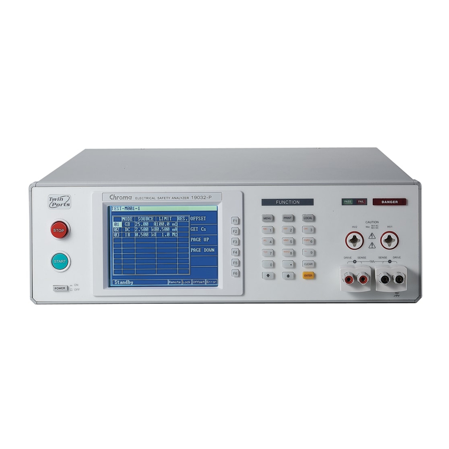
Page 28: Description Of Panel
Electrical Safety Analyzer 19032-P Quick Start Guide Description of Panel Front Panel (10) (11) (12) Display Area (7) (8) (15)(14)(13) Figure 4-1 Front panel includes several function areas which easy to use. This paragraph will introduce each control and information on screen to you. - Page 29 Electrical Safety Analyzer 19032-P Quick Start Guide Display Area Title List: This list displays the current setting of main unit or testing mode. Function key message display area: Under different display menus, there are different function descriptions. The right side of display has corresponding function keys.
- Page 30 Electrical Safety Analyzer 19032-P Quick Start Guide are different functions. The right side of display has corresponding function description. If the description is blank, it means corresponding function is invalid. (5) MENU Key: Under each main display mode, press this key to return to “MAIN MENU”...
-
Page 31: Rear Panel
Electrical Safety Analyzer 19032-P Quick Start Guide Rear Panel (1) (2) (4) (5) (6) (7) (8) (9) (10) (11) (12) Figure 4-2 (1) HV2: Reference terminal of high voltage output terminal (HV1) is low electric potential terminal. (2) HV1: High electric potential terminal of high voltage output. - Page 32 Electrical Safety Analyzer 19032-P Quick Start Guide Option (6000-03): 8 points of HV output. (UL approval) Option (6000-04): HV / LC scanner Option (6000-05): HV / LC scanner with probe Option (6000-06): L-N Scanner & Leakage Current Scanner Option (6000-07): HV / LC...
-
Page 33: Notice Items And Procedures Before Operating
Electrical Safety Analyzer 19032-P Quick Start Guide specification 125V AC current is lower than 1A. S1: T he terminal is short-circuited with COM, recall/read test setting in the first group memory. The terminal is short-circu ited with COM, recall/read test setting in the second group memory. -
Page 34: System Parameter Setting
Electrical Safety Analyzer 19032-P Quick Start Guide System Parameter Setting Operation methods: When title shows “SYSTEM SETUP”, press [ ], [ ] keys to move the highlighted cursor to the parameter item which want to set. Press numeral/character key or Function Keys to set this item parameter data. - Page 35 Electrical Safety Analyzer 19032-P Quick Start Guide Source, please set it as ON. After Fail CONTINUE / RESTART (1) When set as CONTINUE, and RESTART / any one among STEPs judged STOP as No Good. It will continue until all STEPs are tested.
-
Page 36: Hardware/Software Agc
Electrical Safety Analyzer 19032-P Quick Start Guide 4.4.1 Hardware/Software AGC The output voltage is changed by load effect, and then executing AGC function. ACV: 50V~5KV (Hardware AGC is always ON, software AGC initial setting is ON and also can be set as OFF.) DCV: 50V~499V (Hardware AGC initial setting is ON and also can be set as OFF. -
Page 37: Offset
Electrical Safety Analyzer 19032-P Quick Start Guide 4.4.3 OFFSET DC OFFSET: Before testing WDC mode, please connects test cable first. After the fixture is tested, then processes OFFSET for ensure test value accuracy. The current calculation formula: Current reading = Current real measurement value – Offset value. -
Page 38: Memory Management Of Test Parameter And Test Preset Parameter
Electrical Safety Analyzer 19032-P Quick Start Guide Memory Management of Test Parameter and Test Preset Parameter When title display “MAIN MENU”, press Function Key [MEMORY] and then title will display “MEMORY SETUP”. At the same time, the memory can be read, stored or deleted. Each memory includes test parameter, test preset parameter and memory name. -
Page 39: Test For Preset Setting
Electrical Safety Analyzer 19032-P Quick Start Guide Please follows the below procedures to process. When title display “MEMORY SETUP”, press [ ], [ ] keys or Function Key [NEXT PAGE] to move the highlighted cursor to the memory name which want to delete. - Page 40 Electrical Safety Analyzer 19032-P Quick Start Guide PRESET SETUP 01. Pass Hold 02. Step Hold 03. AC Freq. 04. GB Freq. 05. IEC-601 06. GB Voltage 15.0 07. Auto Range 08. Soft. AGC 09. Part No. 10. Lot No. 11. SERIAL No.
- Page 41 Electrical Safety Analyzer 19032-P Quick Start Guide discharge until the test is ended as waveform shown in Note 1. 06 GB Voltage 6.0∼15.0 15.0 It sets open voltage when ground impedance testing. 07 Auto Range ON/OFF OFF It sets withstand voltage auto-range function is open or not.
-
Page 42: Auto Range
Electrical Safety Analyzer 19032-P Quick Start Guide The device will start test when it receives a string command, Note and the format is as same as Serial No. Please refer the description for remote interface. 4.6.3 Auto Range (1) Auto Range function sets as ON. -
Page 43: Start Wait Function
Electrical Safety Analyzer 19032-P Quick Start Guide TEST MODE SOURCE LIMIT RES. OFFSET 1.000 kV 0.503 mA Get Cs PAGE UP PAGE DOWN SCANNER-1 1 2 3 4 5 6 7 8 TEST TIME: 0.0s Remote Lock offset Error Figure 4-5 4.6.4 Start Wait Function... - Page 44 Electrical Safety Analyzer 19032-P Quick Start Guide After DUT is connected, press [Stop] [Test] to start test, meanwhile, GB CONTACT counts down as Figure 4-7 shown. TEST MODE SOURCE LIMIT RES. OFFSET 25.00 A 100.0 mΩ Get Cs PAGE UP...
- Page 45 Electrical Safety Analyzer 19032-P Quick Start Guide TEST MODE SOURCE LIMIT RES. OFFSET Ω 25.01 1.9 m Get Cs PAGE UP PAGE DOWN SCANNER-1 1 2 3 4 5 6 7 8 WAIT GB OPEN.. Remote Lock offset Error Figure 4-9 Meanwhile, the output is stopped and DUT can be changed.
-
Page 46: Description Of Gb-Floating Board
Electrical Safety Analyzer 19032-P Quick Start Guide After GB CONTACT counting down for 3 seconds (Start Wait setting time), then process test is the same as item 4 description. Description of GB-Floating Board 4.7.1 Notice Items before Operating Before turning on power, please peruse “Chapter 3 – Precaution before Use”... - Page 47 Electrical Safety Analyzer 19032-P Quick Start Guide DRIVE+ DRIVE+ SENSE+ SENSE+ GB output GB output SENSE- SENSE- on rear on front panel panel DRIVE- DRIVE- High voltage High voltage output on output on rear panel front panel Figure 4-11 RELAY states:...
- Page 48 Electrical Safety Analyzer 19032-P Quick Start Guide iii. When Channel 3 set to L and HV1 terminal on rear panel set to low voltage terminal, connection diagram of front panel terminal and rear panel terminal is as Figure 4-13 shown:...
-
Page 49: Program Setting
Electrical Safety Analyzer 19032-P Quick Start Guide DRIVE+ DRIVE+ GB output GB output on front SENSE+ SENSE+ on rear panel panel SENSE- SENSE- DRIVE- DRIVE- High voltage High voltage output on output on front panel rear panel Figure 4-14 RELAY states:... - Page 50 Electrical Safety Analyzer 19032-P Quick Start Guide Ground Resistance Test Mode (GB) CURRENT: It sets ground resistance test needed current. Notice: Because the high limit of multiplying test current by resistance can’t higher than 6.3V. High limit of resistance will auto modify to adaptable value when it isn’t correspondence with the above...
- Page 51 Electrical Safety Analyzer 19032-P Quick Start Guide rear panel are short-circuited as Figure 4-15 shown. DRIVE+ DRIVE+ GB output GB output SENSE+ SENSE+ on front on rear panel panel SENSE- SENSE- DRIVE- DRIVE- High voltage High voltage output on output on...
- Page 52 Electrical Safety Analyzer 19032-P Quick Start Guide DRIVE+ DRIVE+ GB output GB output SENSE+ SENSE+ on front on rear panel panel SENSE- SENSE- DRIVE- DRIVE- High voltage High voltage output on output on rear panel front panel Figure 4-16 (b) End test: HV1 terminal on rear panel and HV2 terminal on front panel are also short-circuited.
- Page 53 Electrical Safety Analyzer 19032-P Quick Start Guide DRIVE+ DRIVE+ GB output GB output SENSE+ SENSE+ on front on rear panel panel SENSE- SENSE- DRIVE- DRIVE- High voltage High voltage output on output on rear panel front panel Figure 4-17 Example:...
- Page 54 Electrical Safety Analyzer 19032-P Quick Start Guide than high limit value of leakage current or OFF. DWELL TIME: It sets DWELL needed time, 0 means OFF. (During DWELL TIME, don’t judge the high and low limit value of leakage current. The limitation is not over 1.5 multiples of high limit of setting range or high limit of leakage current.)
- Page 55 Electrical Safety Analyzer 19032-P Quick Start Guide RAMP TIME: The needed time which rises to setting voltage. It inputs 0 to indicate it is OFF. FALL TIME: The needed time which falls from setting voltage value to zero, 0 means OFF.
-
Page 56: Calibration Function
Electrical Safety Analyzer 19032-P Quick Start Guide press START on panel or re-trigger START signal on rear panel. (2) The setting is 0.3 ~ 999sec: When the setting time is up then end the pause mode. Short/Open Circuit Detection Mode (OSC) OPEN CHK: It sets the judgment test result to open condition(compare the test reading with the read standard capacitance value [Cs]). -
Page 57: Key Lock Function
Electrical Safety Analyzer 19032-P Quick Start Guide 4.10 KEY LOCK Function KEY LOCK setting method: When title list shows “MAIN MENU”, if text block “LOCK” isn’t highlighted to press numerical key which corresponds to KEY LOCK then “KEY LOCK” window will be appeared. -
Page 58: Fail Lock Function
Electrical Safety Analyzer 19032-P Quick Start Guide If uershave forgotten password, please follow paragraph 4.9.2 Note “Clear Memory” to clear memory, PASSWORD will be reset to initial value, i.e. 0000. 4.12 FAIL LOCK Function 4.12.1 FAIL LOCK Setting and Usage When title bar shows “MAIN MENU”, press numerical key which is... -
Page 59: Release Fail Lock
Electrical Safety Analyzer 19032-P Quick Start Guide NEW SECURITY CODE is not set). Press [START] key for restarting the test. Press [MENU] to return to MAIN MENU. When 19032 is set as FAIL LOCK ON then to restart, and enter Note TEST menu directly. - Page 60 Electrical Safety Analyzer 19032-P Quick Start Guide Figure 4-19 Figure 4-20 As Figure 4-20, the main unit is under STOP status. NC point is connecting to STOP and NO point connecting to START. Some logical components such as transistor, FET, coupler. Also can be used to connect as control circuit as Figure 4-21.
- Page 61 Electrical Safety Analyzer 19032-P Quick Start Guide 20mS or more 20mS or more Figure 4-21 The relay switch control as Figure 4-19 and photo-coupler control as Figure 4-21 are controlled by component contact. It is effective to avoid error operation system which caused by interference. Although the main unit has a lot of preventions, it is necessary to be careful that interferences result from setting measurement system.
-
Page 62: Output Signal
Electrical Safety Analyzer 19032-P Quick Start Guide 4.14 Output Signal The analyzer includes LED and buzzer two kinds of indication signals. The rear panel of analyzer has the following output signals. UNDER TEST: When the analyzer is under test, the output terminal will short circuit. - Page 63 Electrical Safety Analyzer 19032-P Quick Start Guide...
Need help?
Do you have a question about the 19032-P and is the answer not in the manual?
Questions and answers