Table of Contents
Advertisement
Quick Links
IP2246EN • 2021-05-18
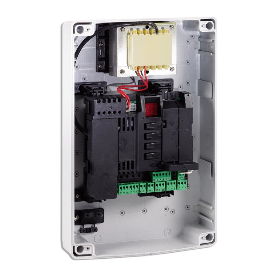
Ditec LCU40H
Control panel installation manual for automations with
one or two 24V motors
(Translation of the original instructions)
TRF
F1
L
N
Alimentazione
Power supply
www.ditecautomations.com
BAT KIT
24V~
UP
DOWN
ENTER
ESC
+
LP
-
36 35 34 33 32 31
24V
24V
Motor 2
Motor 1
Motore 2
Motore 1
A
U
X
1
AUX1 AUX2
1
1
30
30
J14
30 2 3 4 9 13
-
LK
+
30 5 20
0 1 6
A
U
X
2
COM
RDX
J13
JR1
0 1 8
Advertisement
Table of Contents

Related Manuals for DITEC LCU40H


Summary of Contents for DITEC LCU40H
- Page 1 IP2246EN • 2021-05-18 Ditec LCU40H Control panel installation manual for automations with one or two 24V motors (Translation of the original instructions) BAT KIT 24V~ AUX1 AUX2 DOWN ENTER 30 2 3 4 9 13 36 35 34 33 32 31...
-
Page 2: Table Of Contents
Contents Subject Page General safety precautions 1.1 Safety functions EC Declaration of Conformity Technical specifications 3.1 Applications Installation and electrical connections 4.1 Maintenance 4.2 Standard installation 4.3 Standard installation diagram Programming 5.1 Switching the display ON and OFF 5.2 Navigation keys 5.3 Menu map Quick start-up sequences 6.1 Selection of automation type... -
Page 3: General Safety Precautions
1. General safety precautions Failure to observe the information given in this manual may lead to personal injury or damage to the equipment. Keep these instructions for future reference This installation manual is intended for qualified personnel only. Installation, electrical connections and adjustments must be performed in accordance with Good Working Methods and in compliance with the present standards. -
Page 4: Safety Functions
The safety function cannot be bypassed either temporarily or automatically. Fault exclusion has not been applied. 2. EC Declaration of Conformity ASSA ABLOY Entrance Systems AB declares that the Ditec LCU40H control panel complies with the fundamental requisites and other relevant requirements laid down by the following EC di- rectives: EMC Directive 2014/30/EU;... -
Page 5: Installation And Electrical Connections
4. Installation and electrical connections • Perforate the relevant points in the bottom part of the box (Fig. 4.1). • Fix the control panel firmly in place. You are advised to use convex head screws (max head Ø 10mm) with a cross imprint (the centre distance for the holes is shown in Fig. 4.2). •... - Page 6 Fig. 4.1 Fig. 4.2 Fig. 4.3 Fig. 4.4 Fig. 4.5...
-
Page 7: Maintenance
4.1 Maintenance The control panel needs no special maintenance. Make regular checks to ensure the good condition of the box seals and the electrical connections. 4.2 Standard installation Ref. Description Cable Transmitter Flashing light 2 x 1mm² Antenna (integrated in the flashing light) coaxial 50 Ω... -
Page 8: Standard Installation Diagram
4.3 Standard installation diagram... -
Page 9: Programming
5. Programming NOTE: pressure on the keys may be quick (less than 2s) or prolonged (longer than 2s). Unless specified otherwise, quick pressure is intended. To confirm the setting of a parameter, prolonged pressing is necessary. 5.1 Switching the display ON and OFF The procedure to switch on the display is as follows: •... -
Page 10: Menu Map
Menu map Automation Electric lock release time selection Automatic Selection of the closing time Operation time - motor 1 number of gate wings Partial opening measure- Operation time - motor 2 ment adjustment Residential 0 Automatic closing time after partial Function of output -LK+ Residential 1 opening... - Page 11 Loading of last configu- Batteries almost flat ration set Adjustment of approach speed during closure Password setting Battery mode Renew automatic closing time after safety device release Password Selection of opening insertion limit switch mode Learning speed setting Deletion of user settings Selection of closure limit switch mode Selection of device con-...
-
Page 12: Quick Start-Up Sequences
6. Quick start-up sequences 6.1 Selection of automation type Example of PWR25 automation selection → → → → → x2 s Example of PWR35 automation selection → → → → → x2 s NOTE: if no automation is selected (alarm active) using the keys, you can access the values of parameter... -
Page 13: Configuration Of The Limit Switches
6.5 Configuration of the limit switches Example 1 - Door wing stops against mechanical end stops (standard setting) → → → → → → → → Example 2 - Door wing stops against limit switches → → → → → →... -
Page 14: Application Examples
WARNING: Ensure that the forces exerted by the door wings are compliant with EN12453-EN12445 regulations. 7.1 Automations with two swinging gates When the Ditec LCU40H control panel is used in applications for automations with two overlapping swinging gate wings, the following connections can be made:... -
Page 15: Up-And-Over Doors With Two Parallel Motors
7.3 Up-and-over doors with two parallel motors When the Ditec LCU40H control panel is used in applications for automations with up-and-over doors with two parallel motors, the following connections can be made: 3635 34 33 32 31 3635 34 3332 31... -
Page 16: Commands
8. Commands You are advised to read paragraph 11 for all the details about the possible adjustments. WARNING: terminal 30 (common positive for commands) has the same functions as terminal 1, so the commands visible on the display are indicated with 1-5, 1-3, 1-4, etc. It is different from terminal 1, however, because of the maximum current that can be dispensed and it is also active when the control panel is in standby →... -
Page 17: Inserting Plug-In Boards (Aux)
8.1 Inserting plug-in boards (AUX) To access the slots for plug-in boards (AUX): • If you want to insert just one board, cut the control panel cover and remove it as shown in the figure. • If both slots are needed, remove the cover completely. AUX2 AUX1 30 2 3 4 9 13... -
Page 18: Outputs And Accessories
9. Outputs and accessories Value of Output Description accessories Power supply to accessories Output for power supply to external accessories. NOTE: the maximum absorption of 0.5A corresponds to the 24V / 0.5 A sum of all terminals 1. The "gate open" indicator light (30-13) is not calculated in the 0.5A indicated above. - Page 19 Value of Output Description accessories The control panel manages microSD cards for updating the firm- ware and for diagnostics and configuration storage/recovery via MicroSD the in commands → → NOTE: use a microSD with a maximum capacity no greater than 16 Gb.
-
Page 20: Adjustments
Adjustments NOTE: depending on the type of automation and control panel, some menus may not be available. 11.1 Main menu Display Description AT - Automatic Configurations. The menu allows you to manage the automatic configurations of the control panel. BC - Basic Configurations. The menu allows you to display and modify the main settings of the control panel. -
Page 21: Second Level Menu - At (Automatic Configurations)
11.2 Second level menu - AT (Automatic Configurations) Selections Display Description available AS - Automation selection This selection pre-sets the type of motor and a sub-set of parameters linked to the kinematic mechanism of the automation for a standard installation. See "Selection of automation type", paragraph 11.3. -
Page 22: Selecting The Type Of Automation At → As And Specific Default Settings
11.2.1 Selection of automation type → and specific default settings Model R1-R2 VA - VC PO-PC Type of Motor Thrust Speed Learn- Accel- Accel- Ramp automa- circuit during proach eration eration start-up speed tion obsta- opening speed time time speed cles and during during... -
Page 23: Second Level Menu - Bc (Basic Configurations)
11.3 Second level menu - BC (Basic Configurations) Display Description Selections available AC - Enabling of automatic closure ON - Enabled 1-2 - Dependent on input 30-2 SS - Selection of automation status at start OP - Open CL - Closed Indicates how the control panel considers the automation at the time of switch-on, or after a POWER RESET command. -
Page 24: Second Level Menu - Ba (Basic Adjustment)
Display Description Selections available VS - Checking the mechanical end stops When enabled (ON), every time the power supply is connected the automation auto- matically checks the mechanical stops and/or stop limit switches during opening and closing at the speed set with the adjustment →... - Page 25 Display Description Selections available R1 - Adjustment of thrust on obstacles and current - motor 1 [%] The control panel is fitted with a safety device which, when it detects an obstacle: - stops the opening movement and, if outside the limit area for detect- ing obstacles, performs a disengagement operation whose dura- tion can be set with →...
-
Page 26: Additional Ba Level Parameters That Can Be Configured (Available With At → Aa Enabled)
11.4.1 Additional BA level parameters that can be configured (availa- ble with → enabled) Display Description Selections available DT - Adjustment of obstacle recognition time [s/100] 10 - Minimum 60 - Maximum NOTE: the parameter is adjusted in hundredths of a second. ST - Adjustment of start time [s] 0.5 - Minimum 3.0 - Maximum... - Page 27 TO - Setting motor 2 opening delay time [s] Adjustment, in seconds, of the delay time for starting the operation of motor 2, in relation to motor 1. LR - Electric lock release time [s] If enabled, this indicates the electric lock activation time at the start of every opening operation with the automation closed.
-
Page 28: Second Level Menu - Ro (Radio Operations)
Display Description OL - Indicator light for automation open 00 - proportional flashing depending on the point where the gate wings are positioned and the operation direction (in battery mode, the flashing is different) 01 - fixed ON (automation not closed) 02 - output active with automation not open 03 - output active with automation closed 04 - output active with automation open... -
Page 29: Additional Ro Level Parameters That Can Be Configured (Available With At → Aa Enabled)
Selections Display Description available RK - Menu navigation using remote control keyboard ON - Enabled OF - Disabled With the display turned off, quickly type in the sequence of keys 3 3 3 3 2 2 4 4 from the stored remote control you want to use. Make sure all the CH keys are stored. -
Page 30: Second Level Menu - Sf (Special Functions)
Selections Display Description available ER - Deletion of a single remote control → → 2” EA - Total memory deletion → → → 2” 2” RE - Setting memory opening from remote control OF - Disabled ON - Enabled When enabled (ON), the remote programming is activated. To store new remote controls without using the control panel, refer to the remote control instructions. -
Page 31: Additional Sf Level Parameters That Can Be Configured (Available With At → Aa Enabled)
Display Description RL - Loading of last configuration set → → 2” The control panel automatically saves the last configuration set, and keeps it memorised in the storage module or microSD card. In the event of a fault or the replacement of the control panel, the last configuration of the automation can be restored by inserting the storage module or microSD card and loading the configuration in question. -
Page 32: Second Level Menu - Cc (Cycle Counter)
Display Description AR - Alarm reset Resets all the alarms in the memory (counters and log). → 2” NOTE: when the installation has been completed, you are advised to delete the alarms in order to facilitate future checks. AE - Writing of alarms on microSD card Creates a text file on the microSD memory, containing some information about the control panel: the firmware version, operation counters, hour counters, configuration parameters, alarms. -
Page 33: Additional Cc Level Parameters That Can Be Configured (Available With At → Aa Enabled)
11.7.1 Additional CC level parameters that can be configured (available with → enabled) Selections Display Description available CA - Setting the maintenance alarm (factory setting - alarm deactivated: 0.0 00. 00). You can set the required number of operations (regarding the partial operations counter) for signalling the maintenance alarm. -
Page 34: Additional Em Level Parameters That Can Be Configured (Available With At → Aa Enabled)
11.8.1 Additional EM level parameters that can be configured (available with → enabled) Selections Display Description available LL - Voltage threshold for indicating that batteries are almost flat (V) 17 - Minimum 24 - Maximum NOTE: it is set with an interval of sensitivity of 0.5V shown when the decimal point on the right lights up. - Page 35 Display Description Selections available D8 - Selection of device connected to terminals 1-8 NO - None SE - Safety edge S41 - Safety edge with safety test PH - Photocells P41 - Photocells with safety test R9 - Configuration of input 30-9 NO - Disabled 9P - The opening of the input causes a permanent stop 9T - The opening of the input causes a temporary stop.
-
Page 36: Additional Ap Level Parameters That Can Be Configured (Available With At → Aa Enabled)
11.9.1 Additional AP level parameters that can be configured (available with → enabled) Display Description Selections available LU - Setting the courtesy light switch-on time (s) To enable this parameter, set at least one of the selections → → as a courtesy light. It is set with different intervals of sensitivity. - Page 37 Selections Display Description available OT - Selection of type of obstacle 00 - Overcurrent or gate stopped 01 - Overcurrent 02 - Door stopped CR - Stroke estimate correction [%] DO NOT USE (diagnostic purposes only) SM - Selection of operating mode of device connected to terminals 1-6 00 - During the operation, the opening of the safety contact stops the movement (with disengagement if →...
-
Page 38: Diagnostics
See paragraph 11.2.1 12. Diagnostics 12.1 Data Logging integrated in the board LCU40H control panel is equipped with an internal system that allows the Ditec installer to check whether any alarms have been triggered, how many times, and the log of the last twenty alarms. -
Page 39: Exporting Information On The Microsd
→ In this way, at the end of every operation the control panel will save all the events recorded up to that moment on the microSD (in the LCU40H.log file in the LCU40H_ LOG folder). You can view all the recorded logs by inserting the microSD in a PC and opening the LCU40H.log file using the Ditec software. -
Page 40: Signals Visualised On The Display
13. Signals visualised on the display NOTE: depending on the type of automation and control panel, certain visualisations may not be available. 13.1 Display of automation status NOTE: the automation status display mode is only visible with Display visualisation mode set to 02. - Page 41 Display Description Display Description P3 - Partial opening command S2. - Detection of stop during opening - motor 1 3P - Opening command with operator S.2. - Detection of stop during opening - present motor 2 4P - Closing command with operator OO.
-
Page 42: Visualisation Of Alarms And Faults
13.3 Visualisation of alarms and faults WARNING: the visualisation of alarms and faults is possible with any visualisation selec- tion. The signalling of alarm messages takes priority over all other displays. Type of Display Description Operation alarm M0 - Automation type not selected Select a type of automation from the →... - Page 43 Type of Display Description Operation alarm I5 - No voltage 0-1 (faulty voltage regulator Check there is no short-circuit in connec- or short-circuit on accessories) tion 0-1. If the problem persists, replace the control panel. I6 - Excessive voltage 0-1 (faulty voltage Replace the control panel.
- Page 44 Type of Display Description Operation alarm R0 - Insertion of a storage module contain- To save the system configurations on the ing over 100 stored remote controls storage module, delete any stored remote WARNING: the → → setting is controls and bring the total to less than made automatically.
-
Page 45: Troubleshooting
14. Troubleshooting Alarm sig- Problem Possible cause Operation nalling The control panel No power supply. Check the power supply cable and the does not switch on relative wiring Overload on output 0-30 Disconnect any loads connected to ter- minal 30 automation No power. - Page 46 All the rights concerning this material are the exclusive property of ASSA ABLOY Entrance Systems AB. Although the contents of this publication have been drawn up with the greatest care, ASSA ABLOY Entrance Systems AB cannot be held responsible in any way for any damage caused by mistakes or omissions. We re- serve the right to make changes without prior notice.
Need help?
Do you have a question about the LCU40H and is the answer not in the manual?
Questions and answers