Table of Contents
Advertisement
Quick Links
Advertisement
Table of Contents

Summary of Contents for Reiss TARAsys MT10-CL
- Page 1 Operating Instructions TARAsys Measuring Board MT10 April 2021 (EN)
-
Page 2: Table Of Contents
Table of contents Table of contents Information about these Operating Instructions .........4 Symbols and displays ..............4 Related documents ..............5 Information about this product ............7 Product description ..............7 Scope of supply .................8 Product overview ...............9 Safety ....................11 Proper usage ................11 Qualification of the operating staff .......... - Page 3 Table of contents Process display ................ 23 Diagram ................... 24 Login as master ............... 26 Setting the time for the disinfection sensor ....... 26 Connecting the sensor with the controller ......... 27 Controller settings that must not be changed ......28 Calibration ...................
-
Page 4: Information About These Operating Instructions
Information about these Operating Instructions Information about these Operating Instructions Symbols and displays 1.1.1 Safety instructions and warnings In these Operating Instructions, the warning signs and signal words listed below are used. They help you to safely handle the product, prevent injuries to the operating staff and protect the owner against property damage and additional costs. -
Page 5: Related Documents
Symbols and displays used in the text Related documents You can find the data sheets for the measuring board and the electrolysis cell at the following internet address: https://reiss-gmbh.com/?lang=en You can find the data sheet for the inductive proximity switch at the following internet address: https://reiss-gmbh.com/?lang=en... - Page 6 Information about these Operating Instructions You can find the data sheet for the solenoid valve at the following internet address: www.landefeld.de\en, MO 214 ES 24V= The data sheet for the power supply unit is comprised in the scope of supply. 6 / 38 TARAsys...
-
Page 7: Information About This Product
Information about this product Information about this product Product description The measuring board of the TARAsys MT10-CL product line is suitable for measuring chlorine dissolved in water and used as a disinfectant. The areas of application are reverse osmosis systems and drinking water applications. -
Page 8: Scope Of Supply
Information about this product These Operating Instructions exclusively refer to the measuring board equipped with the electrolysis cell. Comply with the operating instructions of the peripheral devices. 2.1.1 Measurand In combination with the TARAline CP4.0H-M4c sensor, the measuring board measures the concentration of total chlorine in the measuring water, i.e. -
Page 9: Product Overview
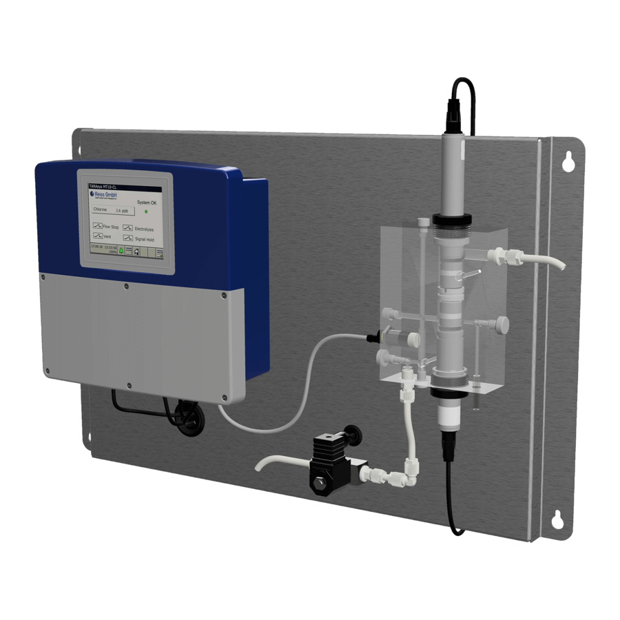
Information about this product Product overview 2.3.1 Measuring board Fig. 1: Product overview Controller Flow control Solenoid valve Measuring water inlet Flow chamber Measuring water outlet Sensor 10 Inductive proximity switch Electrolysis cell Sampler Not included in the scope of supply. For product overview see Chapter 2.3.2 TARAsys 9 / 38... - Page 10 Information about this product 2.3.2 Electrolysis cell Fig. 2: Product overview Electrical connection O-ring 25 x 2.5 Electrode body Hose rings (x2) Anode Membrane cap O-ring 14 x 1.8 10 Cathode Valve opening 11 Electrode finger Membrane disk 12 O-ring 25 x 2.5 10 / 38 TARAsys...
-
Page 11: Safety
Only for the activities described in these Operating Instructions Usage of the board in perfect condition only Use of original accessories and spare parts (see https://www.reiss- gmbh.com) Qualification of the operating staff The operator of the board must have the following qualifications: He/she has read and understood the Operating Instructions. -
Page 12: Residual Risks
Safety Residual risks 3.4.1 Loosening of the screw fittings If not properly fastened, the screw fitting can work loose due to the water pressure or due to vibration. This results in the following risks: The electrolysis cell is pulled out of the flow chamber due to the water ... - Page 13 Safety underpressure in the membrane cap. This can damage the membrane cap. When screwing on the membrane cap, make sure that the valve is not pressed shut (see Chapter 5.2, page 16). Before screwing the membrane cap off, pull the hose ring to the side and keep the valve open (see Chapter 9.2, page 32).
-
Page 14: Installation
Installation Installation Never install or disassemble the measuring board DANGER! when it is energised! There is the risk of electric shock. De-energise the entire system before performing any work. This kind of work must only be performed by skilled staff. Never install the device in potentially explosive atmospheres. - Page 15 Installation Fig. 3: Dimensions Connect the board to the electric mains (observe Chapter 1.2, p. 5). Close the flow control valve Connect the measuring water inlet and measuring water outlet The measuring water outlet must be depressurised. TARAsys 15 / 38...
-
Page 16: Putting The Measuring Board Into Service
Putting the measuring board into service Putting the measuring board into service The measuring board has been mounted and connected to the electric mains (see Chapter 4, p. 14). Installation requirements The following installation requirements must be met: Permanent power supply and presence of measuring water ... - Page 17 Putting the measuring board into service Ensure that the 2 hose rings are in the correct position (see Fig. 5, p. 17). Fig. 5: Position of the rings Place the membrane cap on a clean mat. Fill the membrane cap of the electrolysis cell up to the rim with electrolyte EEZ1.0/W.
- Page 18 Putting the measuring board into service Place the electrode body [1] perpendicularly onto the membrane cap [2]. Turn the electrode body in anti-clockwise direction until the thread is locked in place. Fig. 7: Placing the electrode body onto the membrane cap Electrode body Membrane cap ...
-
Page 19: Preparation Of The Sensor
Putting the measuring board into service Fig. 8: Prepared electrolysis cell Preparation of the sensor The sensor has to be prepared for installation in compliance with the applicable Operating Instructions (see Chapter 1.2, p. 5). Inserting the sensor into the flow chamber ... -
Page 20: Inserting The Electrolysis Cell Into The Flow Chamber
Putting the measuring board into service Fig. 9: Inserting the sensor with retaining ring Sensor O-ring 25 x 2.5 Screw fitting O-ring support Retaining ring O-ring 30 x 2.6 Sliding ring Flow chamber The sensor has been inserted into the flow chamber. Inserting the electrolysis cell into the flow chamber ... - Page 21 Putting the measuring board into service Remove the screw fitting [2] from the flow chamber [5]. Check the O-rings 25 x 2.5 [3 and 4] for proper position at the electrolysis cell [1]. Moisten the O-rings at the electrolysis cell with tap water. ...
-
Page 22: Putting The Flow Chamber Into Service
Putting the measuring board into service Ensure that there is no gap between the electrolysis cell and the sensor as this will impair the function of the electrolysis cell. Screw in the screw fitting up to the stop. The electrolysis cell has now been inserted into the flow chamber. -
Page 23: Operation Of The Controller
Operation of the controller Operation of the controller Process display The process display provides an overview of the state of the measuring board. Here you have the possibility to read the measured value and further digital signals showing the current status of the measuring board. Fig. -
Page 24: Diagram
Operation of the controller 6.1.2 Digital signals 6.1.2.1 Flow Shows the state of the inductive proximity switch. No flow Sufficient flow available 6.1.2.2 Electrolysis Shows the state of the electrolysis cell. Electrolysis cell OFF Electrolysis cell ON 6.1.2.3 Vent (valve) Shows the state of the solenoid valve. - Page 25 Operation of the controller Fig. 12: Diagram Chlorine The current measured value of the chlorine sensor can be read in ppb. Temperature The temperature is read out of the chlorine sensor. The chlorine sensor uses this for internal temperature compensation. TARAsys 25 / 38...
-
Page 26: Login As Master
Operation of the controller Logon as master Push the info button located at the bottom left of the touchscreen Device menu opens Perform the following steps Device menu Logon/Logoff Logon ID input: Master Password: 9200 Fig. 13: Logon as master ... -
Page 27: Connecting The Sensor With The Controller
Operation of the controller Perform the following steps Device menu Configuration Timer Control timer 1 Monday/ Tuesday/ ... Switch-on time 1: enter the desired time OK Fig. 14: Entering the desired time for the disinfection cycle Except for the change of “Switch-on time 1” no other changes must be made at Timers 1 to 4. -
Page 28: Controller Settings That Must Not Be Changed
Operation of the controller Perform the following steps Device menu Digital sensors Select first line Select first line Fig. 15: Connecting the sensor with the controller This has to be done only once for a sensor. Controller settings that must not be changed There are some settings in the controller that must not be changed as they are required for the proper function of the measuring board. - Page 29 Operation of the controller Configuration Digital Sensor 1 IN 1 Limit value monitoring 1 OUT1 and OUT2 Timers 1 to 4 Logic formulas 1 and 2 Mathematical formulas 1, 2 ,3 and 8 Process display 1 ...
-
Page 30: Calibration
Calibration Calibration The sensor puts out a signal that is proportional to the concentration of the disinfectant in the measuring water. The sensor must be calibrated for the allocation of the sensor signal to the concentration of the disinfectant in the measuring water. ... - Page 31 Calibration Take a measuring water sample at the flow chamber for analysis. Determine the concentration of the disinfectant in the measuring water using a suitable analytical measuring method (see operating instructions issued by the manufacturer of the analysis instruments). Enter concentration in ppm ...
-
Page 32: Removal
Removal Removal When the electrolysis cell is removed, a wrong measured value can be present at the input of the measuring and control device and lead to uncontrolled dosing in a control loop. Before removing the electrolysis cell: Switch of the measuring and control system or change to manual operation. - Page 33 Maintenance of the electrolysis cell Fig. 18: Lifting off the hose rings Valve opening 2 pcs hose rings Pour the electrolyte away from the membrane cap. Rinse the electrode finger with tap water. Place special emery paper on a paper towel. ...
-
Page 34: Troubleshooting
Troubleshooting Place one hose ring into its original position. The valve opening has been covered. When changing the membrane cap: Use a new membrane cap. Perform the steps described under “Putting the measuring board into service” (see Chapter 5.2, p. 16). ... -
Page 35: Special Tests
Disassembly and storage 10.1 Special tests 10.1.1 Tightness of the membrane cap of the electrolysis cell Unscrew the membrane cap from the electrolysis cell (see Chapter 9, p. 32). Dry the outside of the membrane cap. Prepare the membrane cap (see Chapter 5.2, p. 16). When screwing the membrane cap back on again, check whether ... -
Page 36: Sensor
Disposal The electrolyte must be removed completely. Otherwise long start-up / response times have to be expected when the cell is put into service again. Rinse the electrode finger with lukewarm tap water. Dry the membrane cap and electrode body in a dust-free place. ... -
Page 37: Liability Disclaimer
Liability disclaimer The warranty will become void in case of mechanical damage or illegible serial number. Sending parts in for inspection: We will only accept shipments that are sent free domicile. Otherwise acceptance will be refused. Subject to their being properly handled, a warranty of one year is granted for inspected parts. - Page 38 Reiss GmbH Eisleber Str. 5 D - 69469 Weinheim Germany...
Need help?
Do you have a question about the TARAsys MT10-CL and is the answer not in the manual?
Questions and answers