Meggitt vibro-meter VM600 Quick Start Manual
Machinery protection system (mps)
Hide thumbs
Also See for vibro-meter VM600:
- Hardware manual (382 pages) ,
- Manual (212 pages) ,
- Quick start manual (56 pages)
Table of Contents
Advertisement
QUICK START MANUAL
Title page
Mk2
VM600
machinery protection system (MPS)
Document reference MAVM600MK2MPS-QS/E
Edition 2 – February 2021
Meggitt SA, Route de Moncor 4, Case postale, 1701 Fribourg, Switzerland
Tel: +41 26 407 1111
Fax: +41 26 407 1660
energy@ch.meggitt.com
www.meggittsensing.com/energy
www.meggitt.com
Advertisement
Table of Contents

Related Manuals for Meggitt vibro-meter VM600


Summary of Contents for Meggitt vibro-meter VM600
- Page 1 QUICK START MANUAL Title page VM600 machinery protection system (MPS) Document reference MAVM600MK2MPS-QS/E Edition 2 – February 2021 Meggitt SA, Route de Moncor 4, Case postale, 1701 Fribourg, Switzerland Tel: +41 26 407 1111 Fax: +41 26 407 1660 energy@ch.meggitt.com www.meggittsensing.com/energy www.meggitt.com...
-
Page 2: Revision Record Sheet
Document released by Technical Publications Peter Ward 17.02.2021 The duly signed master copy of this page is stored by the Technical publications department of Meggitt SA and can be obtained by writing to Technical publications. QUICK START MANUAL Document reference MAVM600MK2MPS-QS/E... -
Page 3: Important Notices
Unless otherwise expressly agreed in writing with Meggitt SA, you assume all risks and liability associated with use of the product. Meggitt SA takes no responsibility for any statements related to the product which are not contained in a current English language Meggitt SA publication, nor for any statements contained in extracts, summaries, translations or any other documents not authored and produced by Meggitt SA. - Page 4 THIS PAGE INTENTIONALLY LEFT BLANK QUICK START MANUAL Document reference MAVM600MK2MPS-QS/E VM600 machinery protection system (MPS) Edition 2 - February 2021...
-
Page 5: Preface
® About Meggitt and vibro-meter Meggitt PLC is a global engineering group, headquartered in the UK, specialising in the design and manufacture of high-performance components and systems for aerospace and energy markets. The Meggitt facility in Fribourg, Switzerland, operates as the legal entity Meggitt SA (formerly ®... - Page 6 The manual is intended for use by qualified personnel, such as operators of process monitoring/control systems using a VM600 machinery protection system (MPS). NOTE: Personnel involved in the installation, operation and maintenance of Meggitt ® vibro-meter systems are assumed to have the necessary technical training in...
- Page 7 Meggitt representative. For further information on the use of a VM600 or VM600 machinery protection system ® (MPS), refer to the following Meggitt vibro-meter documentation: • VM600 machinery protection system (MPS) hardware manual – standard version (document reference MAMPS-HW/E) •...
- Page 8 Getting started with VibroSight installation guide, the VibroSight software release notes and the VibroSight help. NOTE: To ensure that the latest version of documentation is being used, visit the Meggitt ® vibro-meter Energy website at www.meggittsensing.com/energy and check for any updates.
-
Page 9: Safety
SAFETY Symbols and styles used in this manual The following symbols are used in this manual where appropriate: The WARNING safety symbol HIS INTRODUCES DIRECTIVES PROCEDURES OR PRECAUTIONARY MEASURES WHICH MUST BE EXECUTED OR FOLLOWED AILURE TO OBEY A WARNING MIGHT RESULT IN INJURY TO THE OPERATOR AND OR THIRD PARTIES OR RESULT IN DAMAGE TO... - Page 10 All personnel who are liable to operate the equipment described in this manual should be trained in the correct safety procedures. Meggitt does not accept any liability for injury or material damage caused by failure to obey any safety-related instructions or due to any modification, transformation or repair carried out on the equipment without written permission from Meggitt SA.
- Page 11 Hazardous voltages and the risk of electric shock VM600 /VM600 AZARDOUS VOLTAGES EXIST WITHIN A RACK HEN A MODULE CARD PANEL OR POWER SUPPLY IS REMOVED FROM A VM600 /VM600 – RACK THE RACK BACKPLANE CONTAINING HAZARDOUS – VOLTAGES IS EXPOSED AND THERE IS THE RISK OF ELECTRIC SHOCK AS INDICATED BY THE USE OF THE FOLLOWING WARNING LABEL ON THE EQUIPMENT (PCB)
- Page 12 Do not connect with incompatible products or accessories. Only use replacement parts and accessories intended for use with VM600 /VM600 racks that have been approved by Meggitt SA. Using incompatible replacement parts and accessories could be dangerous and may damage the equipment or result in injury.
-
Page 13: Table Of Contents
TABLE OF CONTENTS TITLE PAGE ............. . . i REVISION RECORD SHEET . - Page 14 1.11 MPC4 + IOC4 module network interface ......1-22 1.11.1 Configuring the network interface (IP address) for a MPC4 + IOC4 module .
- Page 15 3.3.3 Displaying information about a MPC4 module ....3-5 3.3.3.1 Notes on displaying information about a MPC4 module ..3-6 3.3.4 Checking the operating mode for a MPC4 module .
- Page 16 THIS PAGE INTENTIONALLY LEFT BLANK QUICK START MANUAL Document reference MAVM600MK2MPS-QS/E VM600 machinery protection system (MPS) Edition 2 - February 2021...
- Page 17 The VM600 series of machinery protection and condition monitoring systems from ® Meggitt’s vibro-meter product line are based around a 19" rack containing various types of modules, depending on the application. There are basically two types of system: •...
-
Page 18: Introduction To The Vm600 Machinery Protection System (Mps)
INTRODUCTION TO THE VM600 MACHINERY PROTECTION SYSTEM (MPS) System overview MPC4 + IOC4 machinery protection and condition monitoring module. The MPC4 + IOC4 machinery protection and condition monitoring module provides 4 dynamic channels and 2 auxiliary channels configurable as either tachometer inputs or DC inputs. -
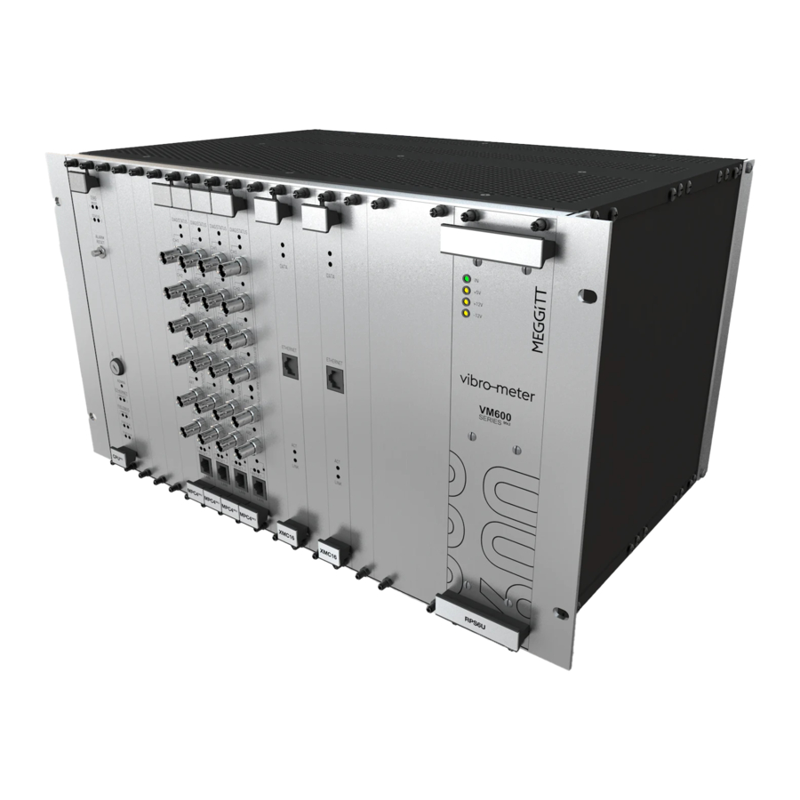
Page 19: Installing A Rack
INTRODUCTION TO THE VM600 MACHINERY PROTECTION SYSTEM (MPS) Installing a rack Finally, a combined machinery protection and condition monitoring system can integrate the following condition monitoring hardware in the VM600 /VM600 rack (ABE04x): • XMx16 + XIO16T extended condition monitoring modules. Figure 1-1 shows front, rear and side views of a typical VM600 system rack (ABE040) - Page 20 INTRODUCTION TO THE VM600 MACHINERY PROTECTION SYSTEM (MPS) Installing a rack Front view VM600 VM600 VM600 VM600 VM600 VM600 MPC4 MPC4 MPC4 MPC4 RPS6U RPS6U (PS2) (PS1) Rear view VM600 VM600 VM600 VM600 VM600 VM600 VM600 RLC16 RLC16 RLC16 Side view Front Figure 1-1: Views of a typical VM600 /VM600 system rack (ABE040)
-
Page 21: Ventilation
INTRODUCTION TO THE VM600 MACHINERY PROTECTION SYSTEM (MPS) Installing a rack Front view Rear view (AC-input version) POWER SUPPLY POWER SUPPLY 90-264 VAC CHECK 100 Wmax Rear view (DC-input version) POWER SUPPLY POWER SUPPLY 18-58VDC CHECK 60Wmax Top view 3D view Figure 1-2: Views of a typical VM600 /VM600 slimline rack (ABE056) with modules/cards installed... - Page 22 INTRODUCTION TO THE VM600 MACHINERY PROTECTION SYSTEM (MPS) Installing a rack for an ABE04x system rack (see Figure 1-3, Case A) and 20 mm for an ABE056 slimline rack (see Figure 1-4, Case It is possible to prevent warm air flowing from one rack to another, by placing inclined plates between them in order to deflect the airflow (see Figure 1-3,...
- Page 23 INTRODUCTION TO THE VM600 MACHINERY PROTECTION SYSTEM (MPS) Installing a rack Case A Natural ventilation Forced ventilation >50 mm >50 mm >50 mm Rack-mounted Fan >50 mm Case B Natural ventilation Forced ventilation VM600 VM600 Front Front rack rack of rack of rack (side view) (Side view)
-
Page 24: Circuit Breaker
INTRODUCTION TO THE VM600 MACHINERY PROTECTION SYSTEM (MPS) Installing a rack Case A Natural ventilation Forced ventilation >20 mm >20 mm >20 mm Rack-mounted Fan >20 mm Case B Forced ventilation Natural ventilation Front Side view of rack Front Side view Rack-mounted Fan of rack >20 mm... -
Page 25: Supply Wiring
INTRODUCTION TO THE VM600 MACHINERY PROTECTION SYSTEM (MPS) Installing a rack For a VM600 /VM600 system rack using a DC-input version of the RPS6U rack power supply, the mains power supply lead (power cord) linking the rack to the mains supply must pass through an external switch or circuit breaker. -
Page 26: Instructions For Locating And Mounting
INTRODUCTION TO THE VM600 MACHINERY PROTECTION SYSTEM (MPS) Installing a rack 1.2.4 Instructions for locating and mounting VM600 /VM600 (ABE04 POPULATED SYSTEM RACK WITH MODULES CARDS AND RACK POWER SUPPLIES INSTALLED IS A HEAVY OBJECT RPS6U EPENDING ON THE NUMBER OF MODULES CARDS AND RACK POWER VM600... -
Page 27: Connecting Power
INTRODUCTION TO THE VM600 MACHINERY PROTECTION SYSTEM (MPS) Connecting power 1.3 Connecting power For a VM600 machinery protection system (MPS) housed in a VM600 /VM600 system rack (ABE04x), the following versions of RPS6U rack power supply are available: • RPS6U power supply for use with an external AC-mains supply. •... -
Page 28: Front Panels
INTRODUCTION TO THE VM600 MACHINERY PROTECTION SYSTEM (MPS) Connecting power 1.3.1 Front panels Figure 1-5 shows the panels of RPS6U rack power supplies with different inputs: AC or DC. IN, AC or DC LED: Green indicates that the external mains supply is present and is within the normal range. -
Page 29: Associated Rear Panels
INTRODUCTION TO THE VM600 MACHINERY PROTECTION SYSTEM (MPS) Handling VM600 modules 1.3.2 Associated rear panels NOTE: For further information on RPS6U power supply configurations, including associated rear panels, refer to a VM600 machinery protection system (MPS) hardware manual. 1.3.3 Power supply check relay The power supply check relay provides an indication that the +5 V, +12 V and −12 V supplies are being correctly generated and delivered by the RPS6U rack power supply or supplies to the VM600... -
Page 30: Vm600 Mk2 /Vm600 Rack Slots / Module Positions
INTRODUCTION TO THE VM600 MACHINERY PROTECTION SYSTEM (MPS) Installing VM600 modules 1.5.1 VM600 /VM600 rack slots / module positions VM600 /VM600 racks are modular systems with different rack slots / module positions as follows: • VM600 /VM600 system rack The VM600 /VM600 system rack (ABE04x) is a 19″... -
Page 31: Installation Restrictions
INTRODUCTION TO THE VM600 MACHINERY PROTECTION SYSTEM (MPS) Installing VM600 modules 1.5.2 Installation restrictions Table 1-1 show the installation restrictions that apply to MPS modules/cards in a VM600 /VM600 system rack (ABE04x). Table 1-1: Attribution of slots in a VM600 /VM600 system rack (ABE04x) Module/card or system component Module/card or system component... - Page 32 INTRODUCTION TO THE VM600 MACHINERY PROTECTION SYSTEM (MPS) Installing VM600 modules Table 1-2 show the installation restrictions that apply to MPS modules/cards in a VM600 /VM600 slimline rack (ABE056). Table 1-2: Attribution of slots in a VM600 /VM600 slimline rack (ABE056) Module/card or system component Module/card or system component slot no.
-
Page 33: Communicating With A Vm600
INTRODUCTION TO THE VM600 MACHINERY PROTECTION SYSTEM (MPS) Communicating with a VM600 1.6 Communicating with a VM600 The various possibilities for communicating with a VM600 machinery protection system ® (MPS) are shown in Figure 1-6. In all cases, a computer running the VibroSight software is required for the configuration, operation and management of the system. - Page 34 INTRODUCTION TO THE VM600 MACHINERY PROTECTION SYSTEM (MPS) Communicating with a VM600 Signal connections VM600 (Rear of rack) MPS rack (ABE04x) (Rack backplane) (Front of rack) ® VibroSight computer System Ethernet (10/100BASE-TX) ® Network VibroSight switch computer system System Ethernet (10/100BASE-TX) Ethernet fieldbus interfaces (Modbus TCP...
-
Page 35: Connecting To A Computer
INTRODUCTION TO THE VM600 MACHINERY PROTECTION SYSTEM (MPS) Connecting to a computer 1.7 Connecting to a computer The MPC4 + IOC4 machinery protection and condition monitoring module has one system communication interface available via the “LAN” connector on the front panel of the MPC4 module (front of VM600 /VM600 rack). -
Page 36: Hardware Configuration
INTRODUCTION TO THE VM600 MACHINERY PROTECTION SYSTEM (MPS) Hardware configuration For example, for a RLC16 module, enabled or disabled, mode (normally energised (NE) or normally de-energised (NDE)), input (logical function), latched or not, for each relay. Individual module settings are configured and summarised on the Configure tab of VibroSight Protect. -
Page 37: Vibrosight Networking
INTRODUCTION TO THE VM600 MACHINERY PROTECTION SYSTEM (MPS) VibroSight networking • For a RLC16 module, jumpers on the module are used to manually configure the VM600 /VM600 rack’s Open Collector (OC) bus and/or Raw bus lines that control and monitor the module’s relays, and distribute the system-wide VM600 safety line control signal. -
Page 38: Vibrosight Network Requirements
INTRODUCTION TO THE VM600 MACHINERY PROTECTION SYSTEM (MPS) MPC4 + IOC4 module network interface If the automatic discovery does not work (for example, due to a network not meeting the requirements of zeroconf), then connections between the VibroSight-system components can be established manually by using the IP addresses of the components. For example, for VibroSight software to VM600 machinery protection system (MPS) module communications, it is possible to connect from VibroSight System Manager to a... - Page 39 INTRODUCTION TO THE VM600 MACHINERY PROTECTION SYSTEM (MPS) MPC4 + IOC4 module network interface Document reference MAVM600MK2MPS-QS/E QUICK START MANUAL Edition 2 - February 2021 VM600 machinery protection system (MPS) 1 - 23...
-
Page 40: Identifying A Mpc4 Mk2 + Ioc4 Mk2 Module In A Configuration
INTRODUCTION TO THE VM600 MACHINERY PROTECTION SYSTEM (MPS) MPC4 + IOC4 module network interface 1.11.1 Configuring the network interface (IP address) for a MPC4 + IOC4 module VibroSight System Manager is used to configure the network interface (IP address) of a MPC4 + IOC module. -
Page 41: Hardware
OVERVIEW OF VM600 MACHINERY PROTECTION SYSTEM (MPS) HARDWARE VM600 racks 2 OVERVIEW OF VM600 MACHINERY PROTECTION SYSTEM (MPS) HARDWARE This chapter provides a brief overview of the VM600 machinery protection system (MPS) hardware. This includes an introduction to the features and basic functionality of the VM600 machinery protection system (MPS) modules: •... - Page 42 OVERVIEW OF VM600 MACHINERY PROTECTION SYSTEM (MPS) HARDWARE MPC4 machinery protection and condition monitoring module 2.2 MPC4 machinery protection and condition monitoring module The MPC4 machinery protection and condition monitoring module panel is shown in Figure 2-1. NOTE: The MPC4 machinery protection and condition monitoring module is always used with an associated IOC4 input/output module as a pair/set of modules...
- Page 43 OVERVIEW OF VM600 MACHINERY PROTECTION SYSTEM (MPS) HARDWARE MPC4 machinery protection and condition monitoring module As shown in Figure 2-1, a MPC4 module has the following LED indicators: • DIAG/STATUS LED In general, this LED is a system/module-level indicator used to indicate the status of the VM600 MPS (MPC4 + IOC...
- Page 44 OVERVIEW OF VM600 MACHINERY PROTECTION SYSTEM (MPS) HARDWARE MPC4 machinery protection and condition monitoring module CHn (dynamic channel) BNC connectors DIAG/STATUS LED indicator: Buffered outputs (“raw” analog signals) • Off: MPC4 + IOC4 module booting. corresponding to dynamic channel inputs. •...
-
Page 45: Mpc4 Mk2 Machinery Protection And Condition Monitoring Module
OVERVIEW OF VM600 MACHINERY PROTECTION SYSTEM (MPS) HARDWARE MPC4 machinery protection and condition monitoring module 2.2.1 MPC4 module LEDs LEDs on the front panel of the MPC4 module are used to indicate the status and behaviour of a VM600 MPS (MPC4 + IOC4 module and any associated RLC16 modules). -
Page 46: Mpc4 Mk2 Module Leds
OVERVIEW OF VM600 MACHINERY PROTECTION SYSTEM (MPS) HARDWARE MPC4 machinery protection and condition monitoring module Table 2-1: Behaviour of MPC4 module LEDs corresponding to module operating firmware (firmware version 640-025-003-000) MPC4 module LEDs Description CHn and/or VM600 DIAG/STATUS LOCK MPS level System booting (start up). - Page 47 OVERVIEW OF VM600 MACHINERY PROTECTION SYSTEM (MPS) HARDWARE MPC4 machinery protection and condition monitoring module Table 2-1: Behaviour of MPC4 module LEDs corresponding to module operating firmware (firmware version 640-025-003-000) (continued) MPC4 module LEDs Description CHn and/or VM600 DIAG/STATUS LOCK MPS level LED test / MPC4 module identification.
- Page 48 OVERVIEW OF VM600 MACHINERY PROTECTION SYSTEM (MPS) HARDWARE MPC4 machinery protection and condition monitoring module Note: blinking slowly. Module/system booting (start up). System operating normally: Configuration as per (b). CH1, CH2, CH3 and AX1 Trip multiply (TM) active. configured and operating normally System locked.
- Page 49 OVERVIEW OF VM600 MACHINERY PROTECTION SYSTEM (MPS) HARDWARE MPC4 machinery protection and condition monitoring module Note: Note: blinking LEDs quickly. blinking slowly. Note: blinking quickly. Configuration as per (b). Configuration as per (b). Configuration as per (b). Alarm bypass (AB) active. Danger alarms for CH1 and CH2 Fail safe: system in safe state.
- Page 50 OVERVIEW OF VM600 MACHINERY PROTECTION SYSTEM (MPS) HARDWARE MPC4 machinery protection and condition monitoring module 2.2.2 MPC4 module buttons Buttons on the front panel of the MPC4 module are used to change/control the operation and behaviour of a VM600 MPS (MPC4 + IOC4 module and any associated RLC16...
-
Page 51: Mpc4 Mk2 Module Buttons
OVERVIEW OF VM600 MACHINERY PROTECTION SYSTEM (MPS) HARDWARE MPC4 machinery protection and condition monitoring module Table 2-3: Behaviour of MPC4 module buttons MPC4 module buttons Description 1 (left) 2 (right) Power-up mode During the start of Power-up mode, press and hold button 1 for at least 5 seconds to force module into Recovery mode Operational mode When Locked (safety/secure operating mode), press button 2... -
Page 52: Mpc4 Mk2 Module Factory Assigned Defaults
OVERVIEW OF VM600 MACHINERY PROTECTION SYSTEM (MPS) HARDWARE MPC4 machinery protection and condition monitoring module 2.2.3 MPC4 module factory assigned defaults 2.2.3.1 MPC4 module as part of a VM600 solution For a MPC4 module delivered as part of a VM600 solution, the module normally runs the latest version of the “standard”... - Page 53 OVERVIEW OF VM600 MACHINERY PROTECTION SYSTEM (MPS) HARDWARE MPC4 machinery protection and condition monitoring module It is important to consider a MPC4 module’s LAN (Ethernet) port settings when connecting a MPC4 module to a computer/network for the first time and/or when reconfiguring or replacing a module in an application.
-
Page 54: Ioc4 Mk2 Input/Output Module
OVERVIEW OF VM600 MACHINERY PROTECTION SYSTEM (MPS) HARDWARE IOC4 input/output module 2.3 IOC4 input/output module The IOC4 input/output module panel is shown in Figure 2-3. NOTE: The IOC4 input/output module is always used with an associated MPC4 machinery protection and condition monitoring module as a pair/set of modules (see 2.2 MPC4 machinery protection and condition monitoring... - Page 55 OVERVIEW OF VM600 MACHINERY PROTECTION SYSTEM (MPS) HARDWARE IOC4 input/output module J1 connector 24-pin S2L connector (male). Compatible with 24-pin B2CF/B2L plug-in connectors (female) with spring connections. Connections: • Inputs (analog signals) for the dynamic channels (CH1 to CH4) and the auxiliary channels (AX1 and AX2). J2 connector 36-pin S2L connector (male).
-
Page 56: Ioc4 Mk2 Module Connector Pinouts
OVERVIEW OF VM600 MACHINERY PROTECTION SYSTEM (MPS) HARDWARE IOC4 input/output module 2.3.1 IOC4 module connector pinouts As shown in Figure 2-3, the IOC4 panel (rear of rack) contains three connectors, identified as J1, J2 and J3. Each connector consists of a male connector (socket on module) and a mating female connector (plug on wiring): •... - Page 57 OVERVIEW OF VM600 MACHINERY PROTECTION SYSTEM (MPS) HARDWARE IOC4 input/output module Table 2-4: IOC4 module J1 connector pinouts IOC4 J1 connector: INPUTS Name / Label Direction Definition function CH1_HI Dynamic channel 1 differential input (high) CH1_SPS Dynamic channel 1 sensor power supply output CH1_LO Dynamic channel 1 differential input (low) SHIELD...
- Page 58 OVERVIEW OF VM600 MACHINERY PROTECTION SYSTEM (MPS) HARDWARE IOC4 input/output module Table 2-5: IOC4 module J2 connector pinouts IOC4 J2 connector: RAW, TTL, DSI, DC OUT Name / Label Direction Definition function RAW_CH1_HI Dynamic channel 1 buffered “raw” output signal RAW_CH1_R Dynamic channel 1 buffered “raw”...
- Page 59 OVERVIEW OF VM600 MACHINERY PROTECTION SYSTEM (MPS) HARDWARE IOC4 input/output module Table 2-5: IOC4 module J2 connector pinouts (continued) IOC4 J2 connector: RAW, TTL, DSI, DC OUT Name / Label Direction Definition function ANA_OUT1_HI Analog (processed DC) output 1 signal ANA_OUT1_R Analog (processed DC) output 1 return ANA_OUT2_HI...
- Page 60 OVERVIEW OF VM600 MACHINERY PROTECTION SYSTEM (MPS) HARDWARE IOC4 input/output module Table 2-6: IOC4 module J3 connector pinouts IOC4 J3 connector: RELAYS Name / Label Direction Definition function FAULT_RLY_ Common-circuit fault relay fused COM contact COM_FUSED FAULT_RLY_ Common-circuit fault relay normally closed (NC) contact FAULT FAULT_RLY_ Common-circuit fault relay common (COM) contact...
- Page 61 OVERVIEW OF VM600 MACHINERY PROTECTION SYSTEM (MPS) HARDWARE IOC4 input/output module 2.3.2 IOC4 module factory assigned defaults 2.3.2.1 IOC4 module as part of a VM600 solution For an IOC4 module delivered as part of a VM600 solution, the IOC4 module’s hardware jumpers are normally pre-configured in the factory for the application before delivery of the system.
-
Page 62: Rlc16 Mk2 Relay Module
OVERVIEW OF VM600 MACHINERY PROTECTION SYSTEM (MPS) HARDWARE RLC16 relay module 2.4 RLC16 relay module The RLC16 relay module panel is shown in Figure 2-4. The RLC16 module is an optional module that can be used with a MPC4 + IOC4 machinery protection and condition monitoring module in order to add additional relays to a system (see 2.2 MPC4... - Page 63 OVERVIEW OF VM600 MACHINERY PROTECTION SYSTEM (MPS) HARDWARE RLC16 relay module J1 connector 16-pin connector (male). Compatible with 16-pin MC/SCF plug-in connectors (female) with screw-terminal connections. Connections: • Outputs (contacts) for relays RL1 to RL6. J2 connector 16-pin connector (male). Compatible with 16-pin MC/SCF plug-in connectors (female) with screw-terminal connections.
-
Page 64: Rlc16
OVERVIEW OF VM600 MACHINERY PROTECTION SYSTEM (MPS) HARDWARE RLC16 relay module 2.4.1 RLC16 module connector pinouts As shown in Figure 2-4, the RLC16 panel (rear of rack) contains three connectors, identified as J1, J2 and J3. Each connector consists of a male connector (socket on module) and a mating female connector (plug on wiring): •... - Page 65 OVERVIEW OF VM600 MACHINERY PROTECTION SYSTEM (MPS) HARDWARE RLC16 relay module Table 2-7: RLC16 module J1 connector pinouts RLC16 J1 connector: RELAYS Name / Label Direction Definition function RLY1_NC Relay 1 normally closed (NC) contact RLY1_NO Relay 1 normally open (NO) contact RLY1_COM Relay 1 common (COM) contact RLY2_NC...
- Page 66 OVERVIEW OF VM600 MACHINERY PROTECTION SYSTEM (MPS) HARDWARE RLC16 relay module Table 2-8: RLC16 module J2 connector pinouts RLC16 J2 connector: RELAYS Name / Label Direction Definition function RLY6_NO Relay 6 normally open (NO) contact RLY6_COM Relay 6 common (COM) contact RLY7_NC Relay 7 normally closed (NC) contact RLY7_NO...
- Page 67 OVERVIEW OF VM600 MACHINERY PROTECTION SYSTEM (MPS) HARDWARE RLC16 relay module Table 2-9: RLC16 module J3 connector pinouts RLC16 J3 connector: RELAYS Name / Label Direction Definition function RLY11_COM Relay 11 common (COM) contact RLY12_NC Relay 12 normally closed (NC) contact RLY12_NO Relay 12 normally open (NO) contact RLY12_COM...
- Page 68 OVERVIEW OF VM600 MACHINERY PROTECTION SYSTEM (MPS) HARDWARE RLC16 relay module 2.4.2 RLC16 module factory assigned defaults 2.4.2.1 RLC16 module as part of a VM600 solution For a RLC16 module delivered as part of a VM600 solution, the RLC16 module’s hardware jumpers are normally pre-configured in the factory for the application before delivery of the system.
- Page 69 OVERVIEW OF VM600 MACHINERY PROTECTION SYSTEM (MPS) HARDWARE Connecting sensors/measurement chains to a VM600 2.5 Connecting sensors/measurement chains to a VM600 Sensors/measurement chains are connected to a VM600 machinery protection system (MPS) via IOC4 input/output modules. 2.5.1 Interfacing to an IOC4 module Detailed information on the IOC4 module’s connector pinouts (definition of terminals) are...
-
Page 70: Connecting Sensors/Measurement Chains To A Vm600 Mk2 Mps
OVERVIEW OF VM600 MACHINERY PROTECTION SYSTEM (MPS) HARDWARE Connecting sensors/measurement chains to a VM600 THIS PAGE INTENTIONALLY LEFT BLANK QUICK START MANUAL Document reference MAVM600MK2MPS-QS/E VM600 machinery protection system (MPS) Edition 2 - February 2021 2 - 30... -
Page 71: Software
® protection system (MPS) hardware, that is, the VibroSight software. ® NOTE: The VibroSight machinery monitoring system software, from Meggitt’s ® vibro-meter product line, is a highly-integrated software suite that supports the effective monitoring of all rotating machinery. ® This includes an introduction to the relevant VibroSight... -
Page 72: Common Vibrosight System Manager Tasks
OVERVIEW OF VM600 MACHINERY PROTECTION SYSTEM (MPS) SOFTWARE Common VibroSight System Manager tasks ® NOTE: The VibroSight software uses VibroSight Protect, a completely separate software module, for the configuration and operation of VM600 machinery protection system (MPS) hardware. This helps ensure complete separation (“segregation”) of machinery protection system (MPS) and condition monitoring system (CMS) functionality in a VM600 /VM600 rack. - Page 73 OVERVIEW OF VM600 MACHINERY PROTECTION SYSTEM (MPS) SOFTWARE Common VibroSight System Manager tasks address (xxx.xxx.xxx.xxx in dot-decimal notation) can be easily changed. The product’s serial number is assigned in the factory during manufacture and cannot be changed, but the product’s IP address (xxx.xxx.xxx.xxx in dot-decimal notation) can be changed to meet the requirements of a network.
-
Page 74: Notes On Configuring The Ip Settings For A Mpc4 Mk2 Module
OVERVIEW OF VM600 MACHINERY PROTECTION SYSTEM (MPS) SOFTWARE Common VibroSight System Manager tasks 3.3.1.1 Notes on configuring the IP settings for a MPC4 module To check that a MPC4 module (or any other VibroSight-compatible device) is connected to your subnet, type ping xxx.xxx.xxx.xxx at a Windows command prompt and then press ENTER (where xxx.xxx.xxx.xxx is replaced by the actual IP address of the device, in dot-decimal notation, as displayed by VibroSight System Manager). - Page 75 OVERVIEW OF VM600 MACHINERY PROTECTION SYSTEM (MPS) SOFTWARE Common VibroSight System Manager tasks In the System Explorer window, VibroSight compatible devices are listed in a serial number (IP address) format. For example: xxxxxxx (xxx.xxx.xxx.xxx) for a VM600 module such as a MPC4 NOTE: It is recommended that VibroSight compatible devices such as a MPC4 module are identified by their serial number (for example, ARxxxxx), as an IP...
- Page 76 OVERVIEW OF VM600 MACHINERY PROTECTION SYSTEM (MPS) SOFTWARE Common VibroSight System Manager tasks The main window (centre) updates to display system information for the MPC4 module, grouped in sections such as General information, Time synchronisation, Network, Diagnostics and Firmware versions. 3.3.3.1 Notes on displaying information about a MPC4 module...
-
Page 77: Changing The Firmware For A Mpc4 Mk2 Module
NOTE: The default folder for the firmware (embedded software) files used by MPC4 modules is: C:\Program Files\Meggitt\VibroSight\Firmware\VM600\MPC4G2 The MPC4 module(s) firmware upgrade window, under Firmware status, updates to display the selected firmware changes. For example: Component: Machinery protection firmware PNR From version 640-025-vvv-ppp to version 640-025-002-000 ARxxxxx (xxx.xxx.xxx.xxx) -
Page 78: Notes On Changing The Firmware For A Mpc4 Mk2 Module
OVERVIEW OF VM600 MACHINERY PROTECTION SYSTEM (MPS) SOFTWARE Common VibroSight System Manager tasks 3.3.6.1 Notes on changing the firmware for a MPC4 module In order to change/upgrade the Operational (Machinery protection) firmware, the MPC4 module must be running either the Operational firmware (Unlocked (maintenance operating mode) only), Recovery firmware or the Proof test firmware. -
Page 79: Common Vibrosight Protect Tasks
OVERVIEW OF VM600 MACHINERY PROTECTION SYSTEM (MPS) SOFTWARE Common VibroSight Protect tasks 3.4 Common VibroSight Protect tasks 3.4.1 Identifying a MPC4 module in a VibroSight Protect (MPS) configuration A VibroSight Protect (MPS) configuration must be able to uniquely identify each MPC4 module (VM600 MPS) in a VM600 /VM600 rack using the module’s IP address. -
Page 80: Identifying A Mpc4 Mk2 Module In A Vm600 Mk2 /Vm600 Rack Using
OVERVIEW OF VM600 MACHINERY PROTECTION SYSTEM (MPS) SOFTWARE Common VibroSight Protect tasks The Serial number and/or IP address for a MPC4 module can be obtained using VibroSight System Manager (see 3.3.3 Displaying information about a MPC4 module). Once the IP address has been configured, the Blink front panel LEDs control can be used to verify communications between... -
Page 81: Mpc4
MPC4 + IOC4 MACHINERY PROTECTION AND CONDITION MONITORING MPC4 module firmware 4 MPC4 + IOC4 MACHINERY PROTECTION AND CONDITION MONITORING MODULE This chapter provides information on the MPC4 + IOC4 machinery protection and condition monitoring module. NOTE: Refer to the VM600 MPC4 + IOC4 machinery protection and condition monitoring module data sheet for detailed information on the key features and... -
Page 82: Module
MPC4 + IOC4 MACHINERY PROTECTION AND CONDITION MONITORING MPC4 module firmware Table 4-1: MPC4 module firmware Description MPC4 module firmware The operational firmware is the main firmware used by the MPC4 module. A MPC4 module will always default Operational firmware to running the operational firmware (if available), after a (640-025-vvv-ppp.Mpc4g2Fw) successful reboot and power-on self-test (POST). - Page 83 MPC4 + IOC4 MACHINERY PROTECTION AND CONDITION MONITORING MPC4 module operating modes 4.2 MPC4 module operating modes The MPC4 module has a number of different operating modes, as shown in Figure 4-1. Note Fail-safe The DIAG/STATUS LED mode indicates the Fail-safe mode. Automatically entered DIAG/STATUS ●: fail-safe.
-
Page 84: Mpc4 Mk2 Module Operating Modes
MPC4 + IOC4 MACHINERY PROTECTION AND CONDITION MONITORING MPC4 module operating modes VibroSight System Manager can be used to display the operating mode of a MPC4 module (see 3.3.4 Checking the operating mode for a MPC4 module). Table 2-1 for information on the behaviour and meaning of the MPC4 module’s LEDs in the following operating modes: Power-up, Operational and Fail-safe. -
Page 85: Fail-Safe Mode
Operational mode. NOTE: A “fatal error” may not be recoverable, for example, if it is related to a persistent hardware problem (failure). Contact Meggitt SA for further information. 4.2.4 Recovery mode A MPC4 module automatically enters the Recovery mode if the module does not have operational firmware. -
Page 86: Mps
MPC4 + IOC4 MACHINERY PROTECTION AND CONDITION MONITORING Resetting a VM600 In the Recovery mode, the MPC4 module’s configuration is automatically erased. NOTE: In the Recovery mode, the MPC4 module’s configuration is automatically erased. Accordingly, after leaving the Recovery mode, a MPC4 module must be configured using VibroSight Protect, before the module can be used in an application. -
Page 87: Service And Support
NOTE: For further information, contact your local Meggitt representative or Meggitt SA (see 5.1 Contacting us). 5.3 Sales and repairs support Meggitt’s sales team provide both pre-sales and post-sales support, including advice on: • New products • Spare parts •... -
Page 88: Repairs And Returns
® If a Meggitt vibro-meter Energy product needs to be returned to Meggitt Switzerland, please ® use the online Energy product return procedure on the Meggitt vibro-meter Energy website at: www.meggittsensing.com/energy/service-and-support/repair NOTE: For further information, refer to a VM600 machinery protection system (MPS) hardware manual or contact us (see 5.1 Contacting...
Need help?
Do you have a question about the vibro-meter VM600 and is the answer not in the manual?
Questions and answers