Table of Contents
Advertisement
Advertisement
Table of Contents

Related Manuals for Vermona DRM1 MK4


Summary of Contents for Vermona DRM1 MK4
- Page 1 DRM1 MKIV USER MANUAL...
-
Page 2: Introduction
- our history. With its first version, we re-entered the market with a first product under the VERMONA brand. A return to a market from which we were forced to withdraw temporarily due to significant historical and political changes. -
Page 3: Table Of Contents
Table of Contents Introduction ............................2 Important Safety Information ......................4 Setup ..............................6 Content ............................6 Connection and getting started ....................6 Setting up audio connections ....................6 Setting up MIDI connections (DIN and USB) ................7 Controls and Connectors ........................8 Front Panel/User Interface ......................8 Rear Panel ...........................9 Sound Generation .......................... -
Page 4: Important Safety Information
Protect the power cord from being stomped on, squeezed, or pinched, particularly near the plugs, mains outlets, and the point where it protrudes from the device! Use only accessories specified by VERMONA! 10. Use only with the trolley, stand, tripod, bracket, or table specified by the manufacturer, or sold... - Page 5 14. WARNING: To reduce the risk of fire or electric shock, do not expose the DRM1 MKIV to rain or moisture! 15. Do not expose the DRM1 MKIV to dripping, splashing, or spraying liquids and make sure that no objects filled with liquids – such as vases, coffee mugs, or beer glasses – are placed on the equipment! 16.
-
Page 6: Setup
Setup Content To warrant top-notch quality, we have carefully inspected the DRM1 MKIV before packaging. Still, there is a tiny chance the unit might have got damaged in transit. Therefore, we ask you to have a close look at the DRM1 MKIV when unpacking. Do not hesitate to contact us, should there be anything unusual with the unit or its packaging. -
Page 7: Setting Up Midi Connections (Din And Usb)
☛ All of the DRM1 MKIV instrument channels sport individual outputs (OUT/ INSERT) , allowing you to patch them into the inputs of a mixing console or of an audio interface. Find more details in chapter “Individual Outputs/Inserts” on page 21. Use the stereo output jacks for the first experiments with your new DRM1 MKIV. -
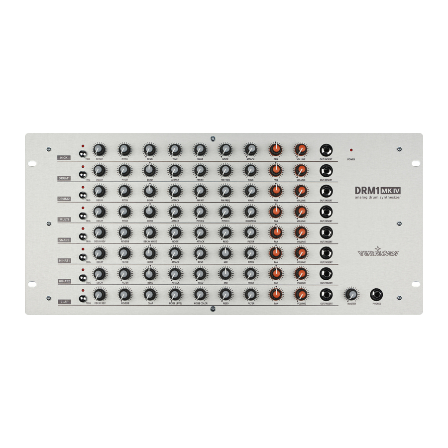
Page 8: Controls And Connectors
Controls and connectors Front Panel/User Interface Figure 1: User Interface of the DRM1 MKIV TRIG button with LED – fires off sound individually per instrument channel Sound-shaping parameters (see “The Instrument Channels of the DRM1 MKIV” on page 11) PAN and VOLUME - channel volume and panning (see “Sound Generation” on page 10) OUT/INSERT - individual outputs/inserts (see “Individual Outputs/Inserts”... -
Page 9: Rear Panel
Rear Panel Figure 2: Rear Panel of the DRM1 MKIV optional TRIGGER inputs for all eight instruments including open/closed hi-hat (please refer to “Trigger Inputs (optional)” on page 23) Main outputs (OUTPUT LEFT and OUTPUT RIGHT). Please refer to page 6. USB port (sends and receives MIDI data and receives firmware updates). -
Page 10: Sound Generation
Sound Generation Now that you have carefully unpacked and set up the DRM1 MKIV, let’s have a closer look at it. Sorry for bothering you with mainly theoretical and safety blurb. This is a necessity to get the most out of this unit in a creative and musical way (and to avoid nasty accidents). -
Page 11: The Instrument Channels Of The Drm1 Mkiv
The instrument channels of the DRM1 MKIV The eight instrument channels are tailored to generate specific drum sounds. However, thanks to their flexibility, you are explicitly asked to experiment and be creative. As you will see, each instrument channel offers a plethora of different sounds. ☛... - Page 12 With pitch modulation being completely absent, bass drums may sound flat and not distinctive; therefore, we recommend at least a little dose of BEND. For creating dance-type kick drums, use higher BEND settings and lower TIME settings. For long booooming kick drums keep the control in the lower half. TIME adjusts the release time of the pitch envelope.
-
Page 13: Drum 1/Drum 2
DRUM 1/DRUM 2 Figure 4: DRUM 1 instrument channel - DRUM 1 and DRUM 2 are identical The two DRUM instrument channels are functionally identical. They are meant to create tom- toms, percussion, and metallic-sounding noises but they can also produce bass drums which have a slightly different character than those created by KICK. -
Page 14: Multi
WAVE is a mix control that continuously sweeps the oscillator waveform from sine-wave to square-wave. Here, the sound changes from soft to edgier. At higher values, the sound will start to get increasingly overdriven and distorted. The interaction bet- ween WAVE and the FM parameters will produce a wide range of timbres for various types of percussion sounds. -
Page 15: Snare
SNARE Figure 6: SNARE instrument channel of the DRM1 MKIV The purpose of the SNARE instrument channel should be obvious. However, due to its various parameters, the snare drum of the DRM1 MKIV is a lot more flexible than what you might have come to expect from other analog drum machines. -
Page 16: Hi Hat 1/Hi Hat 2
☛ Various types of percussion sounds are possible by just using the filter section of the snare drum but leaving out the NOISE component. When FILTER and RESONANCE controls are fully opened, the result will sound clave-like. By attenuating RESONANCE, this sound will morph into a snare that resembles a preset beat-box from 1978 or thereabouts. -
Page 17: Clap
controls the balance between the noisy component part and the detuned multiple oscillator section. Turned fully counterclockwise, only the noise component will be audible; turned fully clockwise, only the multiple oscillator section will be audible, allowing more “authentic” cymbal sounds, thanks to its metallic-sounding charac- ter. - Page 18 REVERB adjusts the intensity of the reverb effect. When this control is set fully counterclock- wise, reverb will be disabled. CLAP sets the rate as well as the number of individual claps (transient spikes) in a row. At fully counterclockwise position, just one single spike / clap will be audible. NOISE controls the color of the noise signal (NOISE parameter) by continuously cross- COLOR...
-
Page 19: Midi Functions
MIDI Functions The DRM1 MKIV receives MIDI notes, including the corresponding velocity data, via the MIDI-In and USB ports. This way, its sounds can be played dynamically. Trigger impulses, received at the optional trigger inputs, will be converted into MIDI note data plus velocity values and transmitted via MIDI-Out and USB ports. -
Page 20: Reset
the assignment. The DRM1 MKIV now automatically advances to the next instrument channel DRUM 1. After that, DRUM 2, MULTI, SNARE, HI HAT 1, HI HAT 2 and finally CLAP will be assigned. When the assignment procedure has been completed, the DRM1 MKIV will automatically return to normal play mode. -
Page 21: Individual Outputs/Inserts
Individual Outputs/Inserts Each instrument channel sports a dedicated individual output/insert which can be used in various ways. Crucial to the function of the outputs is the cable being used or rather – to be more precise – the pin-assignment of the connector that is plugged into the output jack. Using them as individual outputs The OUT/INSERT jack can be used as an individual out in two ways:... -
Page 22: Using Them As An Insert
Using them as an insert The OUT/INSERT jack can also be used to insert external effects processors, such as filters or delays, into that channel. To do so, use a so-called insert cable: OUT/INSERT GROUND SEND RING GROUND RETURN Figure 11: Insert cable Connect the TRS connector to the OUT/INSERT of the respective instrument channel... -
Page 23: Trigger Inputs (Optional)
Trigger Inputs (optional) The DRM1 MKIV is available with optional trigger inputs. If your DRM1 MKIV sports the trigger-in option, please carry on reading. The ten trigger inputs allow triggering the instrument channels of your DRM1 MKIV from a (usually analog) trigger sequencer. - Page 24 Press one of the TRIG buttons KICK, DRUM 1, DRUM 2, or MULTI to select the desired trigger option. The selection will be confirmed by triggering the respective instrument (instrument will sound and its TRIG LED light up). KICK – Gate: The trigger inputs make no use of dynamic response. Each incoming trigger signal exceeding approx.
-
Page 25: Technical Specifications
Technical Specifications Summing Out (MASTER) Implementation 2 x 6.3mm Jack (mono / unbalanced) max. Output Level + 18dBu Out/Insert per Instrument Channel (OUT/ INSERT) Implementation 1 x 6.3mm Jack (stereo / unbalanced) max. Output Level (Tip) + 18dBu max. Input Sensitivity (Ring) + 18dBu Headphone Out Implementation... - Page 26 HDB electronic GmbH Badesteig 20 08258 Markneukirchen GERMANY +49 (0) 37422 4027 0 Email info@vermona.com www.vermona.com...
Need help?
Do you have a question about the DRM1 MK4 and is the answer not in the manual?
Questions and answers