Table of Contents
Advertisement
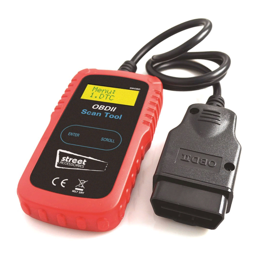
CAN OBD II SCAN TOOL
User Manual
Read & erase diagnostic trouble codes for OBD II compliant vehicles.
PLEASE NOTE: YOU WILL ONLY BE ABLE TO TURN AN ENGINE WARNING LIGHT OFF
WHEN THE PROBLEM CAUSING THE WARNING LIGHT HAS BEEN RESOLVED.
Read and understand these instructions before use and
retain for future reference.
Advertisement
Table of Contents

Related Manuals for Streetwize SWOBD


Summary of Contents for Streetwize SWOBD
- Page 1 CAN OBD II SCAN TOOL User Manual Read & erase diagnostic trouble codes for OBD II compliant vehicles. PLEASE NOTE: YOU WILL ONLY BE ABLE TO TURN AN ENGINE WARNING LIGHT OFF WHEN THE PROBLEM CAUSING THE WARNING LIGHT HAS BEEN RESOLVED. Read and understand these instructions before use and retain for future reference.
- Page 2 Table of Contents 1. Safety Precautions and Warnings................1 2. General Information 2.1 On-Board-Diagnostics (OBD) II................1 2.2 Diagnostic Trouble Codes (DTCs)................2 2.3 Location of the Data Link Connector (DLC).............2 2.4 OBD II Readiness Monitors..................3 2.5 OBD II Monitor Readiness Status................3 2.6 OBD II Terminology....................4 3.
- Page 3 1. Safety Precautions and Warnings To prevent personal injury or damage to vehicles and/or the scan tool, please read this manual rst and follow the following safety instructions whenever working on a vehicle: • Always perform automotive testing in a safe environment. •...
- Page 4 2.2 Diagnostic Trouble Codes (DTCs) OBD II Diagnostic Trouble Codes are codes that are stored by the on-board computer diagnostic system in response to a problem found in the vehicle. These codes identify a particular problem area and are intended to provide you with a guide as to where a fault might be occurring within a vehicle.
- Page 5 2.4 OBD II Readiness Monitors An important part of a vehicle’s OBDII system is the Readiness monitors, which are indicators used to nd out if all of the emissions components have been evaluated by the OBD II system. They are running periodic tests on specic systems and components to ensure that they are performing within allowable limits.
- Page 6 reported as “Ready”, or “Complete”, meaning they have been tested by the OBDII system. The purpose of recording readiness status is to allow inspectors to determine if the vehicle’s OBDII system has tested all the components and/or systems. The powertrain control module (PCM) sets a monitor to “Ready” or “Complete” after an appropriate drive cycle has been performed.
- Page 7 OBDII Drive Cycle-- A specific mode of vehicle operation that provides conditions required to set all the readiness monitors applicable to the vehicle to the “Ready” condition. The purpose of completing an OBD II drive cycle is to force the vehicle to run its onboard diagnostics.
- Page 8 3.2 Product Specifications • Display--Backlit LCD, 2 lines, 8 characters each • Operating Temperature--0 to 50°C (32 to 122 F°) • Storage Temperature-- -20 to 70°C (-4 to 158 F°) • Power--DC12V provided via the vehicle’s battery • , ) " / h t , ) "...
- Page 9 4. Operating Instructions 4.1 Reading Codes CAUTION: Don't connect or disconnect any test equipment with ignition on or engine running. 1. Turn the ignition off. 2. Locate the 16-pin Data Link Connector (DLC) and plug into the Scan Tool cable connector to the DLC.
- Page 10 DTC: 02 IM: YES 7. Select “DTC” from the main menu by pressing the ENTER button. MENU: 1.DTC ● If there are no Diagnostic Trouble Codes retrieved, the display will indicate “NO CODES”. CODES ● If there are any Diagnostic Trouble Codes, then the total number of the Fault Codes followed by that of the Pending Codes will be reported on the display.
- Page 11 with those listed and read the denitions. 4.2 Erasing Codes CAUTION: Erasing the Diagnostic Trouble Codes allows the Scan Tool to delete not only the codes from the vehicle’s on-board computer, but also “Freeze Frame” data and manufacturer specic enhanced data. Further, the I/M Readiness Monitor Status for all vehicle Monitors is reset to Not Ready or Not Complete status.
- Page 12 4.3 Retrieving I/M Readiness Status IMPORTANT: I/M Readiness function is used to check the operations of the Emission System on OBD2 compliant vehicles. It is an excellent function to use prior to having a vehicle inspected for compliance to a state emissions program. An I/M Readiness Status result of “NO”...
- Page 13 • HO2S--O2 Sensor Heater Monitor • EGR-- EGR System Monitor 3. Press the ENTER button to return to the main Menu. 4.4 Viewing VIN Number The View VIN function allows you to retrieve the Vehicle Identication No. on 2002 and newer vehicles that support Mode 9.
- Page 14 5. Diagnostic Trouble Code (DTC) Denitions The following Diagnostic Trouble Code Denitions lists provide only Generic Diagnostic Trouble Codes. For Manufacturer Specic Diagnostic Trouble Code Denitions, consult the vehicle's service manual. CAUTION: Parts or components should not be replaced based on only a DTC without rst consulting the vehicle service manual for more information on possible causes of the fault as well as required testing procedures.
- Page 15 P0026 Intake Valve-Bank 1 Control Solenoid CKT Range/Performance P0027 Exhaust Valve-Bank1 Control Solenoid CKT Range/Performance P0028 Intake Valve-Bank 2 Control Solenoid CKT Range/Performance P0029 Exhaust Valve-Bank2 Control Solenoid CKT Range/Performance P0030 HO2S Bank 1 Sensor 1 Heater Circuit P0031 HO2S Bank 1 Sensor 1 Heater Circuit Low P0032 HO2S Bank 1 Sensor 1 Heater Circuit High P0033...
- Page 16 P0060 HO2S Bank 2 Sensor 2 Heater Resistance P0061 HO2S Bank 2 Sensor 3 Heater Resistance P0062 HO2S Bank 2 Sensor 3 Heater Circuit P0063 HO2S Bank 2 Sensor 3 Heater Circuit Low P0064 HO2S Bank 2 Sensor 3 Heater Circuit High P0065 Air Assisted Injector.
- Page 17 P0094 Fuel System Leak (Small) P0095 IAT Sensor 2 Circuit P0096 IAT Sensor 2 CKT Range/Performance P0097 IAT Sensor 2 Circuit Low P0098 IAT Sensor 2 Circuit High P0099 IAT Sensor 2 CKT Intermittent P0100 MAF or VAF A Circuit Malfunction P0101 MAF or VAF A Circuit Range/Performance P0102...
- Page 18 P0128 Coolant Temp Below Thermostat Regulating Temp P0129 Barometric Pressure Too Low P0130 O2 Sensor Circuit Malfunction (Bank 1 Sensor 1) P0131 O2 Sensor Circuit Low Volts (Bank 1 Sensor 1) P0132 O2 Sensor Circuit High Volts (Bank 1 Sensor 1) P0133 O2 Sensor CKT Slow Response (Bank 1 Sensor 1) P0134...
- Page 19 P0162 O2 Sensor Circuit Malfunction (Bank 2 Sensor 3) P0163 O2 Sensor Circuit Low Volts (Bank 2 Sensor 3) P0164 O2 Sensor Circuit High Volts (Bank 2 Sensor 3) P0165 O2 Sensor CKT Slow Response (Bank 2 Sensor 3) P0166 O2 Sensor CKT No Activity (Bank 2 Sensor 3) P0167 O2 Sensor Heater Circuit Malfunction (Bank 2 Sensor 3)
- Page 20 P0196 Engine Oil Temp Sensor CKT Range/Performance P0197 Engine Oil Temp Sensor Circuit Low Input P0198 Engine Oil Temp Sensor Circuit High Input P0199 Engine Oil Temp Sensor CKT Intermittent P0200 Injector Circuit Open P0201 Injector Circuit Open Cylinder 1 P0202 Injector Circuit Open Cylinder 2 P0203...
- Page 21 P0230 Fuel Pump Primary Circuit Malfunction P0231 Fuel Pump Secondary Circuit Low P0232 Fuel Pump Secondary Circuit High P0233 Fuel Pump Secondary Circuit Intermittent Ckt P0234 Engine Overboost Condition P0235 Turbo/Super Boost Sensor A Circuit Malfunction P0236 Turbo/Super Boost Sensor A CKT Range/Performance P0237 Turbo/Super Boost Sensor A Circuit Low Input P0238...
- Page 22 P0264 Cylinder 2 Injector Control Circuit Low P0265 Cylinder 2 Injector Control Circuit High P0266 Cylinder 2 Contribution Balance Fault P0267 Cylinder 3 Injector Control Circuit Low P0268 Cylinder 3 Injector Control Circuit High P0269 Cylinder 3 Contribution Balance Fault P0270 Cylinder 4 Injector Control Circuit Low P0271...
- Page 23 P0298 Engine Oil Temperature Too High P0299 Turbo/Super Charger UnderBoost P0300 Random/Multiple Cylinder Misfire Detected P0301 Cylinder 1 Misfire Detected P0302 Cylinder 2 Misfire Detected P0303 Cylinder 3 Misfire Detected P0304 Cylinder 4 Misfire Detected P0305 Cylinder 5 Misfire Detected P0306 Cylinder 6 Misfire Detected P0307...
- Page 24 P0332 Knock Sensor 2 Circuit Low Input (Bank 2) P0333 Knock Sensor 2 Circuit High Input (Bank 2) P0334 Knock Sensor 2 CKT Intermittent (Bank 2) P0335 Crankshaft Position Sensor A Circuit Malfunction P0336 Crankshaft Position Sensor A CKT Range/Performance P0337 Crankshaft Position Sensor A Circuit Low Input P0338...
- Page 25 P0367 Camshaft Position Sensor B - Bank 1 Circuit Low Input P0368 Camshaft Position Sensor B - Bank 1 Circuit High Input P0369 Camshaft Position Sensor B - Bank 1 CKT Intermittent P0370 Timing Reference High Resolution Signal A Malfunction P0371 Timing Reference High Resolution Signal A Too Many Pulses P0372...
- Page 26 P0406 EGR Flow Sensor A Circuit High Input P0407 EGR Flow Sensor B Circuit Low Input P0408 EGR Flow Sensor B Circuit High Input P0409 EGR Flow Sensor A Circuit P0410 Secondary Air Injection System Malfunction P0411 Secondary Air Injection System Incorrect Flow P0412 Secondary Air Injection System Valve A Malfunction P0413...
- Page 27 P0440 EVAP Emission Control System Malfunction P0441 EVAP Emission Control System Purge Flow Fault P0442 EVAP Emission Control System Leak (Small) P0443 EVAP Emission Control System Purge Valve C Fault P0444 EVAP Emission Control System Purge Valve C Open P0445 EVAP Emission Control System Purge Valve C Short P0446 EVAP Emission Control System Vent Circuit Malf...
- Page 28 P0474 Exhaust Pressure Sensor CKT Intermittent P0475 Exhaust Pressure Control Valve Circuit Malfunction P0476 Exhaust Pressure Control Valve CKT Range/Performance P0477 Exhaust Pressure Control Valve Circuit Low Input P0478 Exhaust Pressure Control Valve Circuit High Input P0479 Exhaust Pressure Control Valve CKT Intermittent P0480 Cooling Fan 1 Control Circuit P0481...
- Page 29 P0508 Idle Control System Circuit Low P0509 Idle Control System Circuit High P0510 Closed Throttle Position Switch P0511 Idle Air Control Circuit P0512 Starter Signal Circuit P0513 Immobilizer Incorrect P0514 Battery Temperature Sensor CKT Range/Performance P0515 Battery Temperature Sensor Circuit P0516 Battery Temperature Circuit Low P0517...
- Page 30 P0542 Intake Air Heater A Circuit High P0543 Intake Air Heater A Circuit Open P0544 Exhaust Gas Temp. Sensor Circuit (Bank 1 Sensor 1) P0545 Exhaust Gas Temp. Sensor Circuit Low (Bank 1 Sensor 1) P0546 Exhaust Gas Temp. Sensor Circuit High (Bank 1 Sensor 1) P0547 Exhaust Gas Temp.
- Page 31 P0576 Cruise Control Circuit Low Input P0577 Cruise Control Circuit High Input P0578 Cruise Control Multi-Function Input A Circuit Stuck P0579 Cruise Control Multi-Function Input A CKT Range/Performance P0580 Cruise Control Multi-Function Input A Circuit Low P0581 Cruise Control Multi-Function Input A Circuit High P0582 Cruise Control Vacuum Control Circuit Open P0583...
- Page 32 P0610 Control Module Vehicle Options Malfunction P0611 Injector Control Module Performance P0612 Injector Control Module Relay Control P0613 TCM Processor Fault P0614 ECM/TCM Incompatible P0615 Starter Relay Circuit P0616 Starter Relay Circuit Low P0617 Starter Relay Circuit High P0618 Alternative Fuel Module (KAM) Error P0619 Alternative Fuel Module Memory P0620...
- Page 33 P0644 Driver Display Serial Communication Link P0645 A/C Clutch Relay Control Circuit P0646 A/C Clutch Relay Control Circuit Low P0647 A/C Clutch Relay Control Circuit High P0648 Immobilizer Lamp Circuit P0649 Cruise Control Lamp Circuit P0650 MIL Control Circuit Malfunction P0651 Sensor B Reference Voltage Circuit Open P0652...
- Page 34 P0678 Glow Plug/Heater Cylinder 8 P0679 Glow Plug/Heater Cylinder 9 P0680 Glow Plug/Heater Cylinder 10 P0681 Glow Plug/Heater Cylinder 11 P0682 Glow Plug/Heater Cylinder 12 P0683 Glow Plug/Heater Module Communication Problem P0684 Glow Plug/Heater Communication Problem CKT Range/Performance P0685 ECM/PCM Power Relay Control Circuit Open P0686 ECM/PCM Power Relay Control Circuit Low P0687...
- Page 35 P0712 Trans Fluid Temp Sensor A Circuit Low Input P0713 Trans Fluid Temp Sensor A Circuit High Input P0714 Trans Fluid Temp Sensor A CKT Intermittent P0715 Input/Turbine Speed Sensor A Circuit Malfunction P0716 Input/Turbine Speed Sensor A CKT Range/Performance P0717 Input/Turbine Speed Sensor A Circuit No Signal P0718...
- Page 36 P0746 Pres Control Sol. A CKT Performance Or Stuck Off P0747 Pres Control Sol. A Circuit Stuck On P0748 Pres Control Sol. A Circuit Electrical P0749 Pres Control Sol. A CKT Intermittent P0750 Shift Solenoid A Malfunction P0751 Shift Solenoid A CKT Performance Or Stuck Off P0752 Shift Solenoid A Circuit Stuck On P0753...
- Page 37 P0780 Shift Malfunction P0781 1-2 Shift Malfunction P0782 2-3 Shift Malfunction P0783 3-4 Shift Malfunction P0784 4-5 Shift Malfunction P0785 Shift/Timing Solenoid Malfunction P0786 Shift/Timing Solenoid Range/Performance P0787 Shift/Timing Solenoid Low P0788 Shift/Timing Solenoid High P0789 Shift/Timing Solenoid Intermittent Ckt P0790 Normal/Performance Switch Circuit Malfunction P0791...
- Page 38 P0814 Trans Range Display Circuit Malfunction P0815 Upshift Switch Circuit Malfunction P0816 Downshift Switch Circuit Malfunction P0817 Starter Disable Circuit P0818 Driveline Disconnect Switch Input P0819 Up/Down Shift SW Transmission Range Correlation P0820 Gear Lever X-Y Sensor Circuit P0821 Gear Lever X Sensor Circuit P0822 Gear Lever Y Sensor Circuit P0823...
- Page 39 P0848 Trans Fluid Press Sensor/Switch B Circuit High P0849 Trans Fluid Press Sensor/Switch B CKT Intermittent P0850 Park/Neutral Switch Input Circuit P0851 Park/Neutral Switch Circuit Low Input P0852 Park/Neutral Switch Circuit High Input P0853 Drive Switch Input Circuit P0854 Drive Switch Circuit Low Input P0855 Drive Switch Circuit High Input P0856...
- Page 40 P0882 TCM Power Input Signal Low P0883 TCM Power Input Signal High P0884 TCM Power Input Signal CKT Intermittent P0885 TCM Power Relay Control Circuit Open P0886 TCM Power Relay Control Circuit Low P0887 TCM Power Relay Control Circuit High P0888 TCM Power Relay Sense Circuit P0889...
- Page 41 P0916 Gear Shift Position Circuit Low P0917 Gear Shift Position Circuit High P0918 Gear Shift Position CKT Intermittent P0919 Gear Shift Position Control Error P0920 Gear Shift Forward Actuator Circuit Open P0921 Gear Shift Forward Actuator CKT Range/Performance P0922 Gear Shift Forward Actuator Circuit Low P0923 Gear Shift Forward Actuator Circuit High P0924...
- Page 42 P0950 Auto Shift Manual Control Circuit P0951 Auto Shift Manual Control CKT Range/Performance P0952 Auto Shift Manual Control Circuit Low P0953 Auto Shift Manual Control Circuit High P0954 Auto Shift Manual Control CKT Intermittent P0955 Auto Shift Manual Mode Circuit P0956 Auto Shift Manual Mode CKT Range/Performance P0957...
- Page 43 P0984 Shift Solenoid E Control CKT Range/Performance P0985 Shift Solenoid E Control Circuit Low P0986 Shift Solenoid E Control Circuit High P0987 Trans Fluid Press Sensor/Switch E Circuit P0988 Trans Fluid Press Sensor/Switch E CKT Range/Performance P0989 Trans Fluid Press Sensor/Switch E Circuit Low P0990 Trans Fluid Press Sensor/Switch E Circuit High P0991...
- Page 44 RoHS COMPLIANT M17 1RY Streetwize Accessories: Unit 1, Royce Trading Estate, Ashburton Road West, Trafford Park, Manchester M17 1RY Sales enquiries: sales@streetwizeaccessories.com Technical enquiries: support@streetwizeaccessories.com Telephone: 0161 447 8597 www.streetwizeaccessories.com...
Need help?
Do you have a question about the SWOBD and is the answer not in the manual?
Questions and answers