Table of Contents
Advertisement
Quick Links
Chapter 2: Installation
Table of Contents
Chapter 2: Installation � � � � � � � � � � � � � � � � � � � � � � � � � � � � � � � � � � � � � � � � 2-1
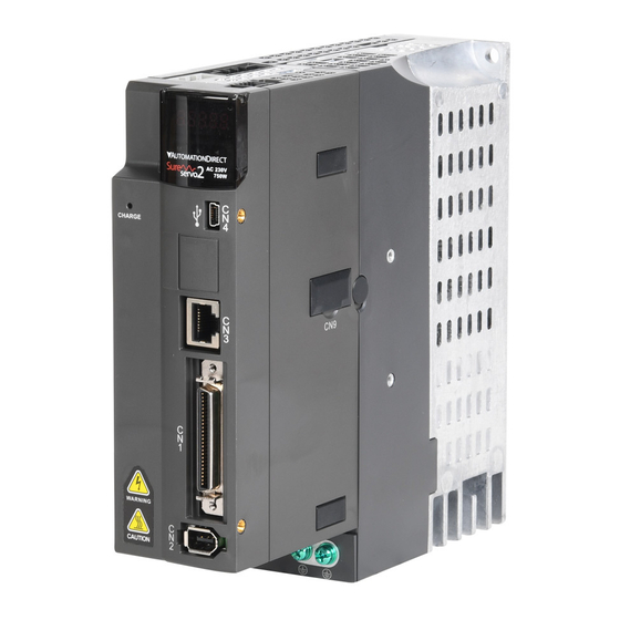
SureServo2™ Installation � � � � � � � � � � � � � � � � � � � � � � � � � � � � � � � � � � � � � 2-2
Safety Precautions � � � � � � � � � � � � � � � � � � � � � � � � � � � � � � � � � � � � � � � � � � � � � 2-2
2�1 - Ambient Storage Conditions � � � � � � � � � � � � � � � � � � � � � � � � � � � � � � � � � � 2-2
2�2 - Ambient Installation Conditions� � � � � � � � � � � � � � � � � � � � � � � � � � � � � � � � � 2-2
2�3 - Mounting direction and space � � � � � � � � � � � � � � � � � � � � � � � � � � � � � � � � � 2-3
2�3�1 - Heat dissipation requirements: � � � � � � � � � � � � � � � � � � � � � � � � � � � � 2-4
2�4 - Safety precautions for using motors � � � � � � � � � � � � � � � � � � � � � � � � � � � � � � 2-5
2�5 - Specifications for the Circuit Breaker and Fuse � � � � � � � � � � � � � � � � � � � � � � � � 2-6
2�6 - Ferrite Ring � � � � � � � � � � � � � � � � � � � � � � � � � � � � � � � � � � � � � � � � � � � � 2-7
2�7 - Installation Requirements for EMC � � � � � � � � � � � � � � � � � � � � � � � � � � � � � � � 2-9
2�7�1 - EMI Filters � � � � � � � � � � � � � � � � � � � � � � � � � � � � � � � � � � � � � � � � 2-10
2�8 - Selecting the regenerative resistor for dynamic breaking � � � � � � � � � � � � � � � � � 2-11
2�9 - The Use of Braking � � � � � � � � � � � � � � � � � � � � � � � � � � � � � � � � � � � � � � � 2-17
SureServo2 User Manual - 1st Edition - 05/20/2021
Chapter
Chapter
Chapter
2
2
2
Page 2-1
Advertisement
Table of Contents

Related Manuals for AutomationDirect SureServo2


Summary of Contents for AutomationDirect SureServo2
-
Page 1: Table Of Contents
SureServo2™ Installation � � � � � � � � � � � � � � � � � � � � � � � � � � � � � � � � � � � � � 2–2... -
Page 2: Sureservo2™ Installation
750W (or above) is 60°C, but the output current is reduced as shown in the figure above; the maximum operation temperature for models of 400W (or below) is 55°C. Page 2–2 SureServo2 User Manual – 1st Edition – 05/20/2021... -
Page 3: 2�3 - Mounting Direction And Space
• Do not obstruct the ventilation holes when mounting the servo drive� Make sure you mount it in the correct orientation or malfunction may occur� CORRECT INCORRECT SureServo2 User Manual – 1st Edition – 05/20/2021 Page 2–3... -
Page 4: 2�3�1 - Heat Dissipation Requirements
(d)* SV2A-2040 Natural cooling Natural cooling and SV2A-2075, 2150, 2200, 2300 forced cooling * Due to the assembly tolerance, the minimum clearance for the servo drive is 1mm. Page 2–4 SureServo2 User Manual – 1st Edition – 05/20/2021... -
Page 5: 2�4 - Safety Precautions For Using Motors
Chapter 2: Installation 2.4 - Safety precautions for using motors The SureServo2 AC servo motor is designed for industrial applications. It is necessary that you fully understand the motor specifications and operation manual. For your safety and correct use, please carefully read the manual, specifications, and precautions for the motor before connecting the motor to any equipment. -
Page 6: 2�5 - Specifications For The Circuit Breaker And Fuse
The SureServo2 drives have an SCCR rating of 5kA. For short circuit protection, choose a current-limiting fuse that limits the let-through current (at your installation's available fault current level) to less than 5,000 Amps. For SureServo2, ADC recommends Class CC or JHL High Speed Class J current-limiting fuses. -
Page 7: 2�6 - Ferrite Ring
The suggested winding methods are shown below: 1) When the wire size (AWG) is small enough to wrap around the ferrite core at least once: Recommended for up to 4.5 kW systems SureServo2 User Manual – 1st Edition – 05/20/2021 Page 2–7... - Page 8 • Only the motor power cable or drive power cable can run through ferrite ring� If needed, please prepare extra ferrite rings for grounding� • An EMI filter may be required for the drive input power for absorbing radiation when using a longer motor power cable� Page 2–8 SureServo2 User Manual – 1st Edition – 05/20/2021...
-
Page 9: 2�7 - Installation Requirements For Emc
This section illustrates the installation requirements for passing the EMC test. Please note that the EMC rating varies based on the installation structure or wiring. SureServo2 products are designed to conform to the specifications of the EMC test. Please refer to the following diagram for the standard installation. -
Page 10: 2�7�1 - Emi Filters
The braided shielding on both ends of the motor cable should be fixed by the EMC cable clamp U-shape saddle and metal plate� Please see the figure below for the correct connection� Page 2–10 SureServo2 User Manual – 1st Edition – 05/20/2021... -
Page 11: 2�8 - Selecting The Regenerative Resistor For Dynamic Breaking
1) Moving direction of the object 2) Direction of torque 3) Regenerative energy The built-in regenerative resistor in the SureServo2 is as follows: SureServo2 User Manual – 1st Edition – 05/20/2021 Page 2–11... - Page 12 Note: If the internal AND an external resistor are both used (the P3-D jumper is NOT removed), make sure that the parallel resistance is still within the specified range for the drive in the table above). Page 2–12 SureServo2 User Manual – 1st Edition – 05/20/2021...
- Page 13 Rotary Motor: Calculation of the regenerative power when there is no external torque, rotor inertia only SureServo2 User Manual – 1st Edition – 05/20/2021 Page 2–13...
- Page 14 SV2M-220B 37�8 SV2M-230N 3000 67�99 24�96 SV2M-230B 57�1 High Inertia SV2H-245N 77�75 99�2 47�36 SV2H-245B 80�65 5500 SV2H-255N 99�78 126�23 47�36 SV2H-255B 102�70 SV2H-275N 142�7 7500 178�84 69�3 SV2H-275B 145�55 Page 2–14 SureServo2 User Manual – 1st Edition – 05/20/2021...
- Page 15 The leading "2" in the equation is for the protection of the resistor sizing and is why P1.053 is double what the drive uses for regen calculations. SureServo2 User Manual – 1st Edition – 05/20/2021 Page 2–15...
- Page 16 N·m), with rotation speed up to 3000 rpm, the required external regenerative resistance is: 3000 rev/min x 2 x π 2 x (0.7 x 1.27 Nm) x = 560W 60 sec/min So, a regenerative resistor of 560W and 40Ω is needed. Page 2–16 SureServo2 User Manual – 1st Edition – 05/20/2021...
-
Page 17: 2�9 - The Use Of Braking
• When the servo drive is off and the time set for P1�043 is not yet reached, but the motor speed is already lower than the speed set for P1�038, DO�BRKR is off (the motor is clamped)� Wiring of the Brake: SureServo2 User Manual – 1st Edition – 05/20/2021 Page 2–17... - Page 18 Calculating the brake’s rated current (SV2L-204N is used as an example here). Power consumption of the brake (20°C) = 6.5 W (refer to Appendix A Motor specifications), so the brake’s rated current = (6.5 W)/24V = 0.27 A. Page 2–18 SureServo2 User Manual – 1st Edition – 05/20/2021...
Need help?
Do you have a question about the SureServo2 and is the answer not in the manual?
Questions and answers