Table of Contents
Advertisement
Quick Links
Advertisement
Table of Contents

Related Manuals for DAYLIFF Poolchlo30

Summary of Contents for DAYLIFF Poolchlo30
- Page 1 POOLCHLOR SALT WATER CHLORINATORS Installation & Operating Manual...
- Page 3 INDEX EQUIPMENT SPECIFICATIONS 2. OPERATING PRINCIPLES 3. WATER CHEMISTRY 4. EQUIPMENT CELL INSTALLTION 5. EQUIPMENT OPERATION 6. MAINTENANCE 7. TROUBLE SHOOTING © Davis & Shirtliff Ltd 2020 Contents herein are not warranted...
-
Page 4: Equipment Specifications
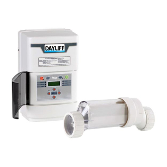
Improved swimming pleasure; Saltwater chlorinated water puts an • end to sore, red eyes and smelly, itchy skin. Dayliff PoolChlor is a high performance, high specification unit that includes the controller, a separate long life electrolysis cell and a flow sensor. -
Page 5: Equipment Specification
• Water temperature indication • Dayliff PoolChlor is a highly effective and efficient pool chlorinator that once fitted will give many years of consistent pool pleasure. APPLICATION For general use pools should be dosed with chlorine at 3gms/m /day and at the PoolChlor output of 30 gms/hr and 50gms/hr. -
Page 6: Installation Layout
INSTALLATION LAYOUT CONTROL MODULE 110/220VDC POWER POOL TIMER SOURCE HEATER/ SOLAR CONTROLS FILTER PRE-FILTER FLOW CELL SWITCH PUMP FROM FROM POOL Fig 1 POOL RETURN RETURN 2. OPERATING PRINCIPLES There are three main components to the PoolChlor system: the Control Unit, the Electrolytic Cell and the Flow Switch. -
Page 7: Salt Levels
Swimming Pools Spas Free Chlorine 1.0 to 3.0 ppm 3.0 to 5.0 ppm Salinity 3000 to 4000pm 3000 to 4000pm 7.2 to 7.8 7.2 to 7.8 Cyanuric Acid (Stabilizer) 60 to 80 ppm 60 to 80 ppm Total Alkalinity 80 to 120 ppm 80 to 120 ppm Calcium Hardness 200 to 400 ppm... - Page 8 When adding large quantities of salt, start with an independent test of the existing salinity level and add in portions, retesting at each stage. NOTE Also it is most important to estimate pool volume in m . This being the product of length x width x average depth in metres.
- Page 9 Ensure that the pool pump and all AC power is turned off before installation. CAUTION Flow Switch To ensure proper operation, verify that the arrow on the flow switch (located on the side) points in the same direction of water flow CAUTION The Flow Switch and Cell are to be fitted into the return line as the last pieces of equipment the water passes through before returning to the pool: i.e...
-
Page 10: Flow Switch
After determining the section of plumbing to install the Flow Switch and Cell, measure out and mark the selected area. 1. To install the Flow Switch, cut out a section of pipe at the desired installation location. Use PVC Primer to clean and prepare the pipe ends and interior of Flow Switch. -
Page 11: Control Unit
Control Unit: The PoolChlor control unit must be mounted a minimum of 1.5m horizontal distance (or more if local codes require) from the pool/spa. The control is designed to mount vertically on a flat surface facing downwards. The back of enclosure also acts as a heat sink (disperses heat from inside the box), hence it is important not to block the back sides of the control unit. -
Page 12: Voltage Conversion
Wiring to Power Source: The Control Unit comes with an un-terminated Power Cord (AC Input) which is typically connected to an external timer, which will turn the pump and Control Unit on and off together. Have the Control Unit wired to the load side of the timer by a qualified person. -
Page 13: Installation Checklist
Fig 6 This set of terminal screws can be located inside of the Control Unit, and accessed by removing the four screws from the Control Unit's aluminum base. The factory voltage setting is the 240V configuration, with a jumper clip inserted between the second and third terminals. -
Page 14: Equipment Operation
If the available chlorine is too high, lower the Output level; if the available chlorine is too low, raise the Output level. It will take a few adjustment to find the ideal setting Once determined, it should only take minor adjustments throughout the season. -
Page 15: Control Buttons
CONTROL BUTTONS: 1. Power: Use this button to manually power the system ON or OFF. 2. Salinity: Displays the average measurement of the most recent salinity levels in the pool water. The average is constantly being updated by real-time salinity readings. - Page 16 Salinity: Located on the Salinity button, this LED is illuminated when the Ÿ button has been pressed to display the salt level reading. No Flow: This LED is illuminated when the Flow Switch has detected no flow. Ÿ This causes the Cell to stop generating chlorine. A flashing LED indicates that the flow is restored, but there will be a 60 second delay before generation is reestablished.
-
Page 17: Maintenance
6. MAINTENANCE To maintain maximum performance, it is recommended that the Cell is removed and visually inspected at least every 3-4 months. The unit will indicate at the appropriate time by flashing the “Check Cell” LED. After inspecting the Cell and cleaning, if necessary press and hold the System Status button next to the display for 5 seconds to reset the flashing “Check Cell”... - Page 18 To clean the Cell of mineral buildup: 1. Attach Cleaning Cap (sold separately) and orient the Cell vertically. Place on the ground and stabilize so as to remain upright and prevent spilling. 2. In a separate bucket, mix one part Hydrochloric acid into four parts water.
- Page 19 HELPFUL NOTES: Proper operation of the chlorine generator can be easily verified by checking the lights on the control panel. However, if the pool remains cloudy, or the chlorine residual tests low, then the chlorine being produced is being lost due to high chlorine demand or improper water conditions.
-
Page 20: Troubleshooting
7. TROUBLE SHOOTING Problem Solution Check input power is connected to the control. Be sure the jumpers are set properly. Verify input voltage with a voltmeter.Check fuse if “Power” LED blown. The board is protected by a 20 amp fuse located on the not on circuit board above the cell connector. - Page 21 Inspect and clean cell according to directions. When done, press “Check Cell” the “diagnostic” button for 3 seconds to stop the “Inspect Cell” LED flashing LED flashing. Remove and inspect the cell for scale. If the cell is scaled, follow the “Check Cell”...
- Page 22 Some yellow algae treatments will use chlorine at a very high rate Low Chlorine and deplete the residual free chlorine. Manually shock the pool if or no indicated in the directions on the algae treatment. It still may be a Chlorine matter of days before the pool returns to “normal”...
-
Page 23: Terms Of Warranty
8. TERMS OF WARRANTY i) General Liability • In lieu of any warranty, condition or liability implied by law, the liability of Davis & Shirtliff (hereafter called the Company) in respect of any defect or failure of equipment supplied is limited to making good by replacement or repair (at the Company's discretion) defects which under proper use appear therein and arise solely from faulty design, materials or workmanship within a specified period. - Page 24 www.davisandshirtliff.com INS393A-03/18...
Need help?
Do you have a question about the Poolchlo30 and is the answer not in the manual?
Questions and answers