Table of Contents
Advertisement
Quick Links
USE AND MAINTENANCE MANUAL
TRANSLATION OF THE ORIGINAL INSTRUCTIONS – ENGLISH
INVERTER
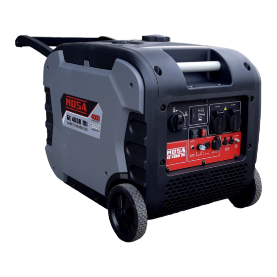
GE 4000 MI
• Gruppo Elettrogeno
• Stromerzeuger
• Generating Set
• Grupo Gerador
• Groupe Electrogene
• Генераторная Установка
• Grupos Electrógenos
• Stroomaggregaten
M A D E
I N
• Skupina generátoru
I T A L Y
language
Codice
Code
Code
Codigo
CK9000119003
Kodezahl
Código
Код
Code
Edizione
Edition
Édition
Edición
09.2020
Ausgabe
Edição
Издание
Editie
Advertisement
Table of Contents

Related Manuals for Mosa GE 4000 MI


Summary of Contents for Mosa GE 4000 MI
- Page 1 USE AND MAINTENANCE MANUAL TRANSLATION OF THE ORIGINAL INSTRUCTIONS – ENGLISH Codice INVERTER Code Code Codigo CK9000119003 Kodezahl GE 4000 MI Código Код Code Edizione Edition Édition • Gruppo Elettrogeno • Stromerzeuger • Skupina generátoru Edición 09.2020 • Generating Set •...
- Page 3 Thank you for choosing a silent inverter gasoline engine generator set of our company. This manual contains the information on how to do that. Please read it carefully before operating. Operating safely and correctly can help you get the best results. All information in this publication is based on the latest product information available at the time of printing.
-
Page 4: Safety Warnings
SAFETY WARNINGS Personal safety and property safety of you and others are very important. . Please read these messages which is preceded by a symbol carefully. NOTICE DANGER You WILL be KILLED or SERIOUSLY HURT if you don’t follow instructions. WARNING You CAN be KILLED or SERIOUSLY HURT if you don’t follow instructions. -
Page 5: Table Of Contents
CONTENTS SAFETY WARNINGS ..............2 SAFETY INFORMATION............4 DESCRIPTION..............8 CONTROL FUNCTION............10 PREPARATION..............13 OPERATION........…......... 15 MAINTENANCE..............21 STORAGE................27 TROUBLESHOOTING............29 SPECIFICATIONS..............30 10. WIRING DIAGRAM.............. 31... -
Page 6: Safety Information
1. SAFETY INFORMATION Read and understand this owner’s manual before operating your generator. It will help you avoid accidents if you get familiar with your generators safe operation procedures. Never use it indoors Never use it in a wet condition Never directly connect it to a home power system... - Page 7 Keep at least 1 meter away from Never smoke when refueling flammable substances Don’t spill when fueling Stop the engine before refueling...
- Page 8 Connections to a Home Power Supply NOTICE If the generator is to be connected to a home power supply as a standby, connection shall be performed by a professional electrician or by another person with proficient electrical skill. When the loads are connected to the generator, please carefully check whether electrical connections are safe and reliable.
- Page 9 System ground The generator has a system ground that connects the generator frame components to the ground terminals on the AC output receptacles. The generator neutral is floating, which means that the AC stator winding is isolated from the grounding fastener and the AC receptacle ground pins.
-
Page 10: Description
DESCRIPTION Carrying handle ① Spark plug maintenance cover ② Fuel tank cap ③ Control panel ④ Recoil starter ⑤ Oil filler cap ⑥ Muffler ⑦... - Page 11 2.1 Electrical components The following components can be selected Components Description 3 in 1 switch knob (including start/stop switch, fuel valve and choke) AC receptacle DC receptacle Indicator light Protector ESC (Engine Smart Control) Ground (earth) terminal Start electric push button...
-
Page 12: Control Function
3. CONTROL FUNCTION 3 in 1 switch knob Engine switch \fuel valve “OFF”; ① Ignition circuit is switched off. Fuel is switched off. The engine will not run. Engine switch \fuel valve \ chock “ON”; ② CHOKE Ignition circuit is switched on. Fuel is switched on. Chock is switched on. The engine can be running. - Page 13 Overload indicator light (Red) The overload indicator light comes on when an overload of a connected electrical device is detected, the inverter control unit overheats, or the AC output voltage ri- ses. Then, the AC protector will trip, stopping power generation in order to protect the generator and any connected electric devices.
- Page 14 DC protector The DC protector turns to “OFF” ② automatically when electric device being con- nected to the generator is operating and current above the rated flows. To use this equipment again, turn on DC protector by pressing its button to “ON” ① ①...
-
Page 15: Preparation
4. PREPARATION 4.1 Fuel DANGER • Fuel is highly flammable and poisonous. Check “SAFETY INFORMATION” ca- refully before filling. • Do not overfill the fuel tank, otherwise it may overflow when the fuel warms up and expands. • After fill the fuel, make sure the fuel tank cap is tightened securely. - Page 16 4 Fill the specified amount of the recommended engine oil, and then install and tighten the oil filler cap. 5 Install the cover and tighten the screws. Recommended engine oil: SAE SJ 10W-40 Recommended engine oil grade: API Service SJ type or higher Engine oil quantity: 0.55 L PRE-OPERATION CHECK WARNING...
-
Page 17: Operation
5. OPERATION WARNING • Never operate the engine in a closed area or it may cause unconsciousness and death within a short time. Operate the engine in a well ventilated area. • Belare starting the engine, do not connect any electric devices NOTICE •... - Page 18 2. Turn the 3 in 1 switch to “CHOKE”. a. Ignition circuit is switched on. b. Fuel is switched on. c. chock is switched off. TIP: The choke is not required to start a CHOKE warm engine. Push the choke knob in to the position “ON”.
- Page 19 2. Disconnect any electric devices. 3. Turn the 3 in 1 switch to “OFF”. a. Ignition circuit is switched off. b. Fuel is switched off. Alternating Current (AC) connection WARNING Be sure any electric devices are turned off before plugging them in. •...
- Page 20 5.4 Battery Charging TIP: • The generator DC rated voltage is 12V. • Start the engine first, and then connect the generator to the battery for charging. • Before starting to charge the battery, make sure that the DC protector is turned 1.
- Page 21 • lt is advisable to check the specific gravity of the electrolytic at least once every hour to prevent overcharging lhe battery. WARNING Never smoke or make and break connections at the battery while charging. Sparks may ignite the battery gas. Battery electrolyte is poisonous and dangerous, causing severe burns, etc.
- Page 22 Generator rated output 3,600W Frequency Power factor ≤3,600W 96W(12V/8.3A ) • the overload indicator light comes on when total wattage exceeds the applica- tion range. OVERLOAD OUTPUT NOTICE • Do not overload. The total load of all electrical appliances appliance must nol exceed the supply range of the generator.
-
Page 23: Maintenance
6. MAINTENANCE The engine must be properly maintained to ensure its operation be safe, economy and trouble-free, as well as eco-friendly. In order to keep your gasoline engine in good working condition, it must be perio- dically serviced. The following maintenance schedule and routine inspection pro- cedures must be carefully followed: Frequency First 1 month... - Page 24 NOTICE • If the gasoline engine frequently works under high temperature or heavy load, change the oil every 25 hours. • If the engine frequently work under dusty or other severe circumstances, clean the air filter element every 10 hours; If necessary, change the air filter element every 25 hours.
- Page 25 Spark plug inspection The spark plug is important engine components, which should be checked perio- dically. 1. Remove the spark plug cap , and Insert the tool through the hol e from the out- side of the cover. Cover 2. Insert the handlebar into the tool and turn it counterclockwise to remove the spark plug.
- Page 26 Carburetor adjustment The carburetor is a vital part of the engine. Adjusting should be left to our company authorized dealer with the professional knowledge, specialized date, and equip- ment to do so properly. Engine oil replacement WARNING Avoid draining the engine oil immediately after stopping the engine. The oil is hot and should be handled with care to avoid burns.
- Page 27 8. Install the oil filler cap. 9. Install the cover and tighten the screws. Air filter 1. Remove the screws and then remove the cover. 2. Remove the screw and then remove the air filter case cover. Air filter Cover 3.
- Page 28 1. Remove the screws, and then pull outward on the areas of the cover shown. 2. Loosen the bolt and then remove the muffler cap, the muffler screen and spark arrester. 3. Clean the carbon deposits on the muffler screen and spark arrester using a wire brush.
-
Page 29: Storage
STORAGE Long term storage of your machine will require some preventive procedures to guard against deterioration. Drain the fuel 1. Turn the 3 in 1 switch to “OFF” ① 2. Remove the fuel tank cap, remove the filter. Extract the fuel from the fuel tank into an approved gasoline container. - Page 30 5. Drain the fuel from the carburetor by loosening the drain screw on the carbure- tor float chamber. 6. Turn the 3 in 1 switch to “OFF”. 7. Tighten the drain screw. 8. Install the cover and tighten the screws. 9.
-
Page 31: Troubleshooting
TROUBLESHOOTING Engine won’t start 1. Fuel systems No fuel supplied to combustion chamber. No fuel in tank ... Supply fuel. ○ Clogged fuel filter ..Clean fuel filter. ○ Clogged Carburetor..Clean carburetor. ○ 2. Engine oil system Insufficient Oil level is low ..Add engine oil. -
Page 32: Specifications
SPECIFICATIONS Item 4kW Generator Type Silent Inverter Rated frequency (Hz) Rated voltage (V) Rated output power (kW) Maximum output power (kW) Generator Power factor Charging Voltage (DC) (V) Charging Current (DC) (A) Non-fuse Protector Overload Protect (DC) Single Phase Engine 225I Single cylinder, 4-Stroke, forced air cooling, Engine type... -
Page 33: Wiring Diagram
WIRING DIAGRAM... - Page 36 MOSA div. della BCS S.p.A. Viale Europa, 59 20090 Cusago (Milano) Italy Tel.+39 - 0290352.1 Fax +39 - 0290390466 www.mosa.it...
Need help?
Do you have a question about the GE 4000 MI and is the answer not in the manual?
Questions and answers