Advertisement
Quick Links
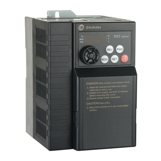
Shihlin Electric SS2 Series AC Drive
Installation Guide
SS2-021-0.4K~2.2K
SS2-023-0.4K~3.7K
SS2-043-0.4K~5.5K
Thank you for choosing Shihlin SS2 series AC Drive.
The instruction will describe on the use and points for attention of products. Before installing, please be sure to carefully read the
Instruction, so that the inverter can be used in proper and safe way.
1)
Safety Instructions
Safety Instructions
Installation, operation, maintenance and inspection must be performed by qualified personnel.
In this instruction, the safety instruction levels are classified into "Warning" and "Caution".
Warning: Incorrect handling may cause hazardous conditions, resulting in death or severe injury.
Caution: Incorrect handling may cause hazardous conditions, resulting in medium or slight injury, or may cause only material damage.
Warning
While the inverter power is ON, do not open the front cover or the wiring cover. Do not run the inverter with the front cover or the wiring cover
removed. Otherwise you may access the exposed high voltage terminals or the charging part of the circuitry and get an electric shock.
It is crucial to turn off the motor drive power before any wiring installation or inspection is made. Even if power supply was cut off, residual voltage is
in the internal capacitor. After the power cut off, waiting time should be no shorter than the time in inverter logo.
The inverter must be connected to the ground properly.
Do not operate or touch the radiator or handle the cables with wet hands. Otherwise you may get an electric shock.
Do not change the cooling fan while power is ON. It is dangerous to change the cooling fan while power is ON.
Caution
The voltage applied to each terminal must be the ones specified in the Instruction Manual. Otherwise burst, damage, etc. may occur.
Don't conduct a pressure test on components inside inverter, for semiconductor of inverter is easily to be broke down and damaged by high voltage.
While power is ON or for some time after power-OFF, do not touch the inverter as it will be extremely hot. Touching these devices may cause a burn.
The cables must be connected to the correct terminals. Otherwise burst, damage, etc. may occur.
The polarity (+ and -) must be correct. Otherwise burst, damage, etc. may occur.
Inverter must be installed on a nonflammable wall without holes (so that nobody touches the inverter heat sink on the rear side, etc.). Mounting it to
or near flammable material may cause a fire.
If the inverter has become faulty, the inverter power must be switched OFF. A continuous flow of large current may cause a fire.
2) Description of Product Model Number
SS2 - 043 - 0.75K
- * *
Series category
Voltage level
Capacity
SS2 series
-043:440V three-phase
0.75kW
-023:220V three-phase
-021:220V single-phase
3)
Installation Environment
Ambient temperature
-10 ~ +50℃ (non-freezing).
Ambient humidity
Below 90%Rh (non-condensing).
Storage temperature
-20 ~ +65℃.
Surrounding environment
Indoor, no corrosive gas, no flammable gas, no flammable powder.
Altitude
Altitude below 1000 meters
Vibration
Below 5.9m/s
2
(0.6G).
Grade of protection
IP20
The degree of pollution
2
4) Installation and Wiring
Please ensure vertical arrangement to keep the cooling effect:
(a) Vertical arrangement
(b)Horizontal arrangement
(c) Level arrangement
Please comply with installation conditions shown below to ensure enough ventilation space and wiring space for inverter
cooling
Arrangement of single or paralleling inverter:
A
C
A
C
E
B
D
A
C
F
E
B
D
A
C
F
Size
Frame A
Frame B
A
50
50
B
50
50
C
100
100
D
50
50
E
50
50
F
ventilation direction
Arrangement of multiple inverters:
Inverter
Inverter
Compact Design Vector control AC Drive
Enclosure
(a)Horizontal arrangement
Note1: When mounting inverters of different sizes in parallel, please align the clearance below each inverter to install, which is easy to change the cooling
fan.
Note2: When it is inevitable to arrange inverters vertically to minimize space,take such measures as to provide guides since heat from the bottom
inverters can increase the temperatures in the top inverters, causing inverter failures.
Installation of DIN rail:
(a) installation
5) Terminal Connection Diagrams
Others
None:General model
-**:Customer motor or dedicated motor or region
difference
6) Main Circuit Wiring and Terminal Specification
The inverter
model
specifications
SS2-043-0.4K
SS2-021-0.4K
SS2-023-0.4K
SS2-043-0.75K
SS2-021-0.75K
SS2-023-0.75K
SS2-043-1.5K
SS2-023-1.5K
SS2-021-1.5K
SS2-043-2.2K
Unit :mm
SS2-021-2.2K
SS2-023-2.2K
SS2-043-3.7K
SS2-043-5.5K
SS2-023-3.7K
Inverter
Inverter
Guide
Guide
Guide
Inverter
Inverter
Enclosure
(b)Vertical arrangement
2
1
(b) disassembly
Recommended wiring specification(mm
)
Recommended wiring specification (AWG)
2
Terminal
Tightening
screw
torque
U、V、
+/P、
Grounding
(Kgf.cm)
R、S、T
R、S、T
W
PR
Cable
1.5
1.5
1.5
1.5
16
2.5
2.5
2.5
2.5
14
2.5
2.5
2.5
2.5
14
2.5
2.5
2.5
2.5
14
M3.5
12.2
2.5
2.5
2.5
2.5
14
2.5
2.5
2.5
2.5
14
2.5
2.5
2.5
2.5
14
2.5
2.5
2.5
2.5
14
2.5
2.5
2.5
2.5
14
2.5
2.5
2.5
2.5
14
4
4
4
4
12
M4
18
4
4
4
4
12
2.5
2.5
2.5
2.5
10
2.5
2.5
2.5
2.5
14
4
4
4
4
12
7) Control Terminal
Arrangement of control terminal
Control terminal description
Terminal type
Terminal name
STF
STR
There are totally eight multi-function control
M0
terminals, which can
Digital signal
M1
SINK/SOURCE.
input
M2
RES
SD
Digital signal ground
PC
In Source mode, digital signal power.
The terminal inside with +12v power is allowable
10
load current with 5 mA..
Analog signal
2
Voltage is 0~5v or 0~10v or 4~20mA input point,
input
4
to set the target frequency.
5
common reference of 10, 2, 4, and AM terminal
A
Multi-function relay output terminals.
Relay output
B
A-C is the normally open contact, B-C is the
C
normally close contact.
Communication
The
RJ45
terminal
converter and the upper machine/DU06.
External simulation table, indicating the output
frequency or output current。
Note: output voltage of AM is PWM pulse form,
Analog output
AM
therefore the analog voltage only is suitable for
terminals
external moving coil type header, not suitable for
connect to the digital meter header or as A/D
conversion signal to PLC and controller use.
This terminal is also known as the "multi-function
SO
Collector output
output terminal".
SE
Reference to the open collector output
Note1:When connecting control terminal with external devices, please pay attention to the voltage and current specifications of terminals, avoiding
damaging the inverter.
Note2:The function of the control terminal is decided by inverter parameters, please refer to Instruction Manual for setting.
Note3: Please pay attention to polarity when connecting external power and devices.
Wiring method
Power supply connection
For the control circuit wiring, strip off the sheath of a cable, and use it with a blade terminal. For a single wire, strip off the sheath of
the wire and apply directly.
Insert the blade terminal or the single wire into a socket of the terminal.
(1) Strip off the sheath for the below length. If the length of the sheath peeled is too long, a short circuit may occur with neighboring
wires. If the length is too short, wires might come off.
Wire the stripped cable after twisting it to prevent it from becoming loose. In addition, do not solder it.
7mm
(2) Crimp the blade terminal.
Insert wires to a blade terminal, and check that the wires come out for about 0 to 0.5 mm from a sleeve.
Check the condition of the blade terminal after crimping. Do not use a blade terminal of which the crimping is inappropriate, or the
U、V、
+/P、
Grounding
face is damaged.
W
PR
Cable
16
16
16
0~0.5mm
Please do use blade terminals with insulation sleeve. Blade terminals commercially available:
14
14
14
Cable gauge
Blade terminals model
(mm²)
14
14
14
0.3
AI 0,25-6 WH
0.5
AI 0,5-6 WH
14
14
14
0.75
AI 0,75-6 GY
0.75(for two wires)
AI-TWIN 2×0,75-6 GY
14
14
14
14
14
14
14
14
14
14
14
14
Note1: Please Use a small flat head screw driver (tip thickness: 0.6 mm, width: 3.0mm). If a flat head screw driver with a narrow tip is used, terminal
block may be damaged.
14
14
14
Note2: Tightening torque is 3.2~4.8kgf.cm, too large tightening torque can cause screw slip, too little tightening torque can cause a short circuit or
malfunction.
14
14
14
Wiring Precautions
12
12
12
After wiring, wire offcuts must not be left in the inverter.
12
12
12
Wire offcuts can cause an alarm, failure or malfunction. Always keep the inverter clean.
14
14
14
When drilling holes in a controller, please take caution not to allow chip powder to enter the inverter.
To prevent a malfunction due to noise, keep the signal cables 10 cm (3.94 inches) or more away from the power cables. Also,
14
14
14
Separate the main circuit cables at the input side from the main circuit cables at the output side.
12
12
12
Set the voltage/current input switch correctly. Incorrect setting may cause a fault, failure or malfunction.
Function instructions
Terminal specifications
Input impedance: 4.7 kΩ
Action current:5mA (when 24VDC)
switch
the mode of
Voltage range: 10~28VDC
Maximum frequency: 1kHz
---
The voltage is +24V, the allowable load current is 50mA
Maximum current:10mA
Input impedance:10 kΩ
---
Contact ability VDC30V/VAC230V-0.3A
communication
interface
of
frequency
Highest rate:19200bps
Longest distance:500m
Output signal: DC 0~10V
Load current : 1mA
Contact ability VDC 24V-0.1A
d1
Crimping tool
L (mm)
d2 (mm)
Manufacturer
(mm)
product number
10.5
0.8
2
12
1.1
2.5
Phoenix Contact
CRIMPFOX 6
12
1.3
2.8
Co., Ltd.
12
1.3
2.8
Advertisement

Summary of Contents for Shihlin SS2 Series
- Page 1 Enclosure Enclosure Control terminal description (a)Horizontal arrangement (b)Vertical arrangement Thank you for choosing Shihlin SS2 series AC Drive. Terminal type Terminal name Function instructions Terminal specifications Note1: When mounting inverters of different sizes in parallel, please align the clearance below each inverter to install, which is easy to change the cooling The instruction will describe on the use and points for attention of products.
- Page 2 3:Reserved Restart coasting time 0~30s, 9999 0: Modbus protocol P.57 9999 P.33 Communication protocol selection 1: Shihlin protocol Restart cushion time 0~60s P.58 0: Write parameters in communication XXX0: the default value, reserved mode, write into RAM and EEPROM. P.34...
- Page 3 Parameter User Name Setting range Default number setting 0: The range for the input voltage signal Parameter User Parameter User Name Setting range Default Name Setting range Default (terminal 2-5) is 0~5V number setting number setting P.73 Voltage signal selection 1:The range for the input voltage signal 0: Digital input terminal power unable P.94...
- Page 4 Cooling fan operation selection 3:The fan will be turned on when the To improve our products, the parameters and contents may be modified, please contact the agent or refer to Shihlin websites temperature of the heat sink is higher than 60℃.
Need help?
Do you have a question about the SS2 Series and is the answer not in the manual?
Questions and answers