Table of Contents
Advertisement
Advertisement
Table of Contents

Subscribe to Our Youtube Channel
Related Manuals for TEXA NAVIGATOR TXT MULTIHUB


Summary of Contents for TEXA NAVIGATOR TXT MULTIHUB
- Page 1 ENGLISH..............5...
-
Page 3: Table Of Contents
3.2 General Rules....................8 3.3 Operator Safety....................9 3.4 Tool Safety......................10 3.5 Disclaimer.......................11 4 OPERATION OF THE RADIO DEVICES...........12 5 ENVIRONMENTAL INFORMATION............13 6 NORMATIVE INFORMATION..............14 7 NAVIGATOR TXT MULTIHUB..............16 8 DESCRIPTION...................18 9 TECHNICAL FEATURES................19 10 DISPLAY....................22 10.1 Communication.....................22 10.2 Battery......................22 10.3 Status......................23 10.4 Other Messages...................24... - Page 4 13.3 Network Cable....................36 13.4 USB ......................37 14 DIAGNOSIS....................39 14.1 DoIP diagnosis....................40 14.2 STANDARD diagnosis..................42 14.3 Pass-Thru.....................43 14.4 Dynamic Tests....................45 14.5 Disconnection at the End of a Diagnosis............49 15 FIRMWARE UPDATE................50 16 MAINTENANCE..................51 17 TROUBLESHOOTING................52 18 LEGAL NOTICES..................55...
-
Page 5: Revision Of The Manual
NAVIGATOR TXT MULTIHUB TECHNICAL MANUAL 1 Revision of the Manual This document is the technical manual for the product:NAVIGATOR TXT MULTIHUB Document Review Number:05 Date of Issue:15/03/2021... -
Page 6: Introduction
TEXA S.p.A. tool has been used based on the information within this manual. Any additions to this manual, useful in describing the new versions of the program and new functions associated to it, may be sent to you through our TEXA technical bulletin service. -
Page 7: Legend Of The Symbols Used
2 LEGEND OF THE SYMBOLS USED Toxic material hazard Risk of crushing hands Explosive material hazard Floor level obstacle warning Electric shock hazard Laser beam hazard temperature danger Electromagnetic field hazard freezing Flammable material hazard General Risk Hot surface hazard Obligation to read the instructions Corrosive substance hazard Safety glasses required... -
Page 8: Safety Rules
The personnel in charge of using the diagnostic tools are required to follow the general safety rules and to use the NAVIGATOR TXT MULTIHUB device for its intended use only and to carry out the maintenance as described in this manual. -
Page 9: Operator Safety
• Do not remove or damage the labels and the warnings on the tool; do not in any case make them illegible. • Do not remove or tamper with any safety devices the tool is equipped with. 3.3 Operator Safety The airbags inflate with great force. -
Page 10: Tool Safety
3.4 Tool Safety The tool was designed to be used in specific environmental conditions. Using the tool in environments with temperature and humidity values that differ from those specified may impair its efficiency. Safety measures: • Put the tool in a dry area. •... -
Page 11: Disclaimer
• Do not use external batteries to supply the tool unless explicitly requested to do so by the software. • Pay the utmost attention to battery terminals and cables when setting up the connection to the vehicle. This will avoid false contacts and/or accidentally connecting the cables to metallic parts of the vehicle being tested. -
Page 12: Operation Of The Radio Devices
The Bluetooth and WiFi interfaces look for compatible electronic devices according to the radio signal they emit and establish a connection between them. TEXA tools select and only prompt you with compatible TEXA devices. This does not exclude the presence of other sources of communication or disturbance. -
Page 13: Environmental Information
5 ENVIRONMENTAL INFORMATION Do not dispose of this product with other undifferentiated solid waste. For information regarding the disposal of this product please see the pamphlet supplied. -
Page 14: Normative Information
6 NORMATIVE INFORMATION Simplified EU Declaration of Conformity The manufacturer, TEXA S.p.A., declares that the type of NAVIGATOR TXT MULTIHUB radio equipment is compliant with the following directives: • RED 2014/53/UE The complete text of the EU declaration of conformity is available at the following Internet address http://www.texa.it/download. -
Page 16: Navigator Txt Multihub
• the resetting of the oil change, service and airbag system warning lights; • the configuration of the control units, keys and remote controls. NAVIGATOR TXT MULTIHUB is compatible with the J2534 protocol and therefore allows performing repairs that require reprogramming the control units. - Page 17 This allows recording any issues that may be difficult to replicate in the workshop. The data is analysed using a specific software once you return to the workshop. The Bluetooth and Wi-Fi technologies allow NAVIGATOR TXT MULTIHUB to connect to the following display units: •...
-
Page 18: Description
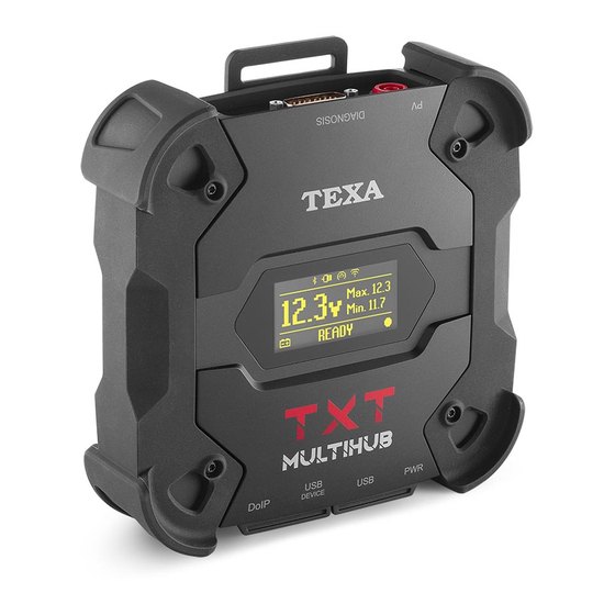
8 DESCRIPTION 1. DIAGNOSIS connector 2. PV connector 3. Display 4. DoIP* connector 5. USB DEVICE* connector 6. USB* connector 7. PWR* connector (*) Equipped with protective cap. -
Page 19: Technical Features
9 TECHNICAL FEATURES Manufacturer: TEXA S.p.A. Product name: NAVIGATOR TXT MULTIHUB • Type: iMX6 1 GHz Main processor: • RAM: 512 MByte • Mass Storage: eMMC 8 GByte • Type: STM32F439 168 MHz Coprocessor: • RAM: 2 MByte SRAM, 8 MByte SDRAM •... - Page 20 User interface: Display OLED 64x128 dot Operating temperature: 0 ÷ 50 °C Storage temperature: - 20 ÷ 60 °C Operating moisture: 10% ÷ 80% without condensation Dimensions [mm]: Weight: 600 g IP protection level: IP53 * (*) With properly closed protective caps. Directives: RoHS 2011/65/UE RED 2014/53/UE...
- Page 21 CONNECTOR PINOUT DSUB-26HD ISO 22900-1 Manuf. Discretionary diagnostic line 14 CAN L +J1850 15 L-Line Manuf. Discretionary diagnostic line 16 Unswitched battery voltage Power ground 17 Ext. Adapter ID0 Signal Ground 18 Ext. Adapter ID1 CAN H 19 SPI OUT K-Line 20 SPI IN Manuf.
-
Page 22: Display
10 DISPLAY The VCI has a display that acts as the user interface. The display is divided into areas: 1. Communication 2. Battery 3. Status 10.1 Communication This area shows the current communication mode with the display unit. Communication Display No communication mode configured. -
Page 23: Status
Connector Used for Power Supply Connector Used for Voltage Reading Icon DIAGNOSIS DIAGNOSIS DIAGNOSIS + PWR DIAGNOSIS The following values are displayed: • instantaneous • maximum[Max.] • tickover[Min.] In case of dual power supply, if the voltage read via the DIAGNOSIS connector drops below a given threshold, the displayed values refer to the voltage on the PWR connector. -
Page 24: Other Messages
The VCI is being powered by the vehicle battery via the DIAGNOSIS connector. The VCI is being powered via the PWR connector. The VCI is turning off. The VCI is restarting after a short interruption of the power supply. For further information see the DIAGNOSIS chapter. 10.4 Other Messages Other messages that may appear in the VCI display can be about: Progress status of the VCI firmware update procedure. -
Page 25: Power Supply
11 POWER SUPPLY The VCI does not have an internal battery and can be powered: • by the battery in the vehicle being tested, using the specific wiring; When the device is powered using a diagnostic cable connected to the DIAGNOSIS connector, the VCI displays the vehicle's battery voltage. -
Page 26: Obd Socket
11.1.1 OBD socket Power can be supplied to the VCI via the OBD socket of the vehicle being tested, by connecting a specific diagnostic cable to the DIAGNOSIS connector. The image is only an example: the position of the OBD socket and the type of diagnostic cable may change based on the vehicle being tested. -
Page 27: Battery Cable
11.1.2 Battery Cable The VCI can be powered with a specific wiring to be connected to the battery in the vehicle being tested via the PWR connector. If the battery is in the rear part of the vehicle, we recommend connecting the VCI directly to the power supply points coming from the battery that are available near the area in which you are operating. -
Page 28: Power Supply Cable
The VCI displays the following screen if no communication modes with the display unit have been configured. 11.1.3 Power Supply Cable The VCI can be powered by means of a power supply cable with clamps connected to specific diagnostic cables. The image is only an example: the position of the diagnostic socket and the type of diagnostic cable may change based on the vehicle being tested. - Page 29 If the battery is in the rear part of the vehicle, we recommend connecting the VCI directly to the power supply points coming from the battery that are available near the area in which you are operating. Use the battery power only when specifically requested by the software.
-
Page 30: Cigar Lighter Cable
11.1.4 Cigar lighter cable The VCI can be powered by the battery in the vehicle being tested using the PWR connector. The image is only an example: the position of the cigar lighter socket may change based on the vehicle being tested. Always refer to the documentation supplied by the vehicle manufacturer for the positioning and correct access to the cigar lighter socket. -
Page 31: Power On/Off
12 POWER ON/OFF In all the power source connection and disconnection operations, please refer to the safety indications in the POWER SUPPLY and DIAGNOSIS chapters in order to reduce the risk of electric shock. 12.1 Power on The VCI turns on automatically once it is connected to one of the power sources described previously. -
Page 32: Boot Down
12.2 Boot down To turn off the VCI, you must disconnect it from the power source. Proceed as follows: Disconnect the VCI from the power source. The VCI turns off. Generally, if the tool is powered via OBD connector, just turn off the vehicle by turning the ignition key to the OFF position (ignition off). -
Page 33: Communication
13 COMMUNICATION The VCI communicates with the control units in the vehicle being tested via connection to the vehicle's diagnostic socket through the specific diagnostic cable indicated by the software. The VCI has various communication modes, some of which are reserved for specific types of diagnosis: •... -
Page 34: Wi-Fi
2. Turn on the display unit. 3. Start the diagnostic software. 4. Launch the VCI configuration function. 5. Follow on screen instructions. For further information, see the software operating manual. When turning on the VCI, the first available mode is selected (e.g.: Wi-Fi). If, during use, the mode in use is no longer available (e.g.: no signal), the connection will automatically shift to the first available mode (e.g.: Bluetooth). - Page 35 During the Wi-Fi connection configuration part, you may be required to enter the credentials to access the network to which you wish to connect the VCI. The credentials are obtained automatically if the tool is connecting to the same network as the display unit or to one of the networks configured in it.
-
Page 36: Bluetooth
13.2 Bluetooth The Bluetooth connection is the alternative to the Wi-Fi connection for wireless communication between the VCI and the display unit. The Bluetooth communication is only possible with display units with Bluetooth 2.1 or higher. To configure the communication properly you must use the serial number indicated on the data plate on the VCI. -
Page 37: Usb
The following screen indicates that the VCI is connected to the display unit in the desired mode and is awaiting commands. For further information, see the software operating manual. 13.4 USB The connection via USB between the tool and the display unit can only be established through the USB DEVICE connector. - Page 38 All the ongoing processes through the USB connector are immediately stopped as soon as the tool detects the cable connection to the USB DEVICE connector, which may compromise any ongoing assistance operations (e.g.: firmware update via USB drive) through the connector USB. Do not use this connection mode during assistance operations that require using the connector USB.
-
Page 39: Diagnosis
14 DIAGNOSIS The protocols supported by the VCI allow it to perform various types of diagnoses. The type of diagnosis that can be carried out depends on the vehicle being tested and its compliance with specific protocols for communication with the control units. The type of diagnosis also determines the communication mode between the VCI and the display unit. -
Page 40: Doip Diagnosis
In some cases, specific adapters may be required. Using a wrong diagnostic cable or a cable not specifically designed for this tool may prevent a correct diagnosis and/or damage the tool and the vehicle. Only use the diagnostic cables indicated by the diagnostic software. - Page 41 Proceed as follows: 1. Start the diagnostic software. 2. Select the vehicle you wish to work on. 3. Select the system you wish to diagnose. 4. Select the desired variant. 5. Connect the VCI to the vehicle following the support information provided by the software.
-
Page 42: Standard Diagnosis
14.2 STANDARD diagnosis The STANDARD diagnosis is a type of diagnosis based on the diagnostic protocols indicated in the TECHNICAL FEATURES chapter, except for protocol UDP/TCP ISO 13400 (DoIP). The following communication modes are available for this type of diagnosis: •... -
Page 43: Pass-Thru
Pass-Thru service(s) are specifically determined by each manufacturer; costs, performances and procedures may therefore vary independently of what TEXA S.p.A establishes. Each manufacturer imposes specific hardware and operating system requirements for the PC where its software will be installed. - Page 44 Reprogramming or calibrating the control units may require you to download specific files from the vehicle manufacturer's website. A high-speed connection to the Internet is highly recommended. The vehicle manufacturer is entitled to request specific documentation to independent vehicle repairers (e.g.: Chamber of Commerce company registration showing that the company is actually registered in the register of vehicle repairers) so that they can carry out reprogramming operations on security systems (e.g.: immobiliser and/or antitheft control units).
-
Page 45: Dynamic Tests
TEXA S.p.A. is not, under any circumstance, liable for repair and maintenance work carried out on vehicles using the Technical Information and/or Services offered by the specific websites of each manufacturer. In this respect, the use of Pass-Thru mode is subject to the acceptance of specific Liability regulations defined by each vehicle manufacturer. - Page 46 I.INSTALLATION 1. Turn off the vehicle (instrument panel off). 2. Locate the OBD connector. 3. Carefully remove any panels protecting the OBD connector. For further information, please refer to the documentation provided by the vehicle manufacturer. 4. Connect the diagnostic cable to the DIAGNOSIS connector on the VCI. 5.
- Page 47 Improperly fastening the VCI and diagnostic cable may cause the VCI itself or the diagnostic cable to fall, which may be a hindrance to vehicle driving and to the proper operation of safety devices. Secure the VCI and the diagnostic cable so as to minimise their risk of falling.
- Page 48 The software provides the sequence of operations required to complete the procedure in order to configure the VCI. The VCI displays the following screen during the configuration phase. 17. Follow the information that appear on screen. 18. Close the diagnostic software. 19.
-
Page 49: Disconnection At The End Of A Diagnosis
The analysis of the collected data is performed by the specific software. In order to analyse the results of the dynamic tests, you must connect the VCI to the display unit and download the recorded data. The software allows you to view specific reports for the data stored. 20. -
Page 50: Firmware Update
15 FIRMWARE UPDATE The firmware in the VCI is updated through a specific software function and requires the connection to the display unit. Connection to the display unit may be established via: • WiFi • USB The available connection modes depend on the display unit used;... -
Page 51: Maintenance
• only use original spare parts or spare parts approved by the manufacturer; • contact your retailer for extraordinary maintenance operations; For further help, contact your retailer or the technical assistance service. You can see the list of authorised retailers at the following address:https://www.texa.com/sales-network... -
Page 52: Troubleshooting
17 TROUBLESHOOTING For any technical problem contact your retailer/distributor. Below you will find a list of simple instructions that the customer can carry out without having to ask for technical assistance. POSSIBLE PROBLEM POSSIBLE CAUSE SOLUTION The diagnostic cable is not properly Connect the cable connected. - Page 53 PROBLEM POSSIBLE CAUSE POSSIBLE SOLUTION The display unit is off. Turn on the display unit. The communication configuration Perform the communication procedure has not been carried configuration procedure. out. The VCI and the display unit are Move the VCI and the display outside Wi-Fi/Bluetooth unit closer.
- Page 54 POSSIBLE PROBLEM POSSIBLE SOLUTION CAUSE The type of Wi-Fi Connect to a type of network among the network you wish to supported ones. connect the VCI to further information The VCI does not is not among the COMMUNICATION chapter. communicate with supported ones.
-
Page 55: Legal Notices
18 LEGAL NOTICES TEXA S.p.A. Via 1 Maggio, 9 - 31050 Monastier di Treviso - ITALY Tax Code - Company Register of Treviso ID No. - VAT No.: 02413550266 Single-shareholder company subject to the direction and coordination activities of Opera Holding S.r.l.
Need help?
Do you have a question about the NAVIGATOR TXT MULTIHUB and is the answer not in the manual?
Questions and answers