Table of Contents
Advertisement
Ethernet Gateways for MPI/PPI/PROFIBUS
®
Manual for all NETLink
Ethernet versions:
700-881-MPI21
700-882-MPI21
700-884-MPI21
dition 3 / 16.02.2021 / ab FW 2.58
E
Order number of manual: 900-88X-MPI21/en
Helmholz GmbH & Co. KG | Hannberger Weg 2 | D-91091 Großenseebach | Germany
Phone +49 9135 7380-0 | Fax +49 9135 7380-110 | info@helmholz.de | www.helmholz.com
Advertisement
Table of Contents

Related Manuals for Helmholz NETLink 700-881-MPI21


Summary of Contents for Helmholz NETLink 700-881-MPI21
- Page 1 3 / 16.02.2021 / ab FW 2.58 Order number of manual: 900-88X-MPI21/en Helmholz GmbH & Co. KG | Hannberger Weg 2 | D-91091 Großenseebach | Germany Phone +49 9135 7380-0 | Fax +49 9135 7380-110 | info@helmholz.de | www.helmholz.com...
- Page 2 (photocopy, microfilm, or other method) without the express written permission of Helmholz GmbH & Co.KG, not even for use as training material, or using electronic systems. All rights reserved in the case of a patent grant or registration of a utility model or design.
- Page 3 Revision history of this document: Edition Date Revision 16.06.2012 Summary of all Ethernet variants 16.03.2015 NETLink Switch deleted; Troubleshooting supplements 16.02.2021 General updates NETLink ® Ethernet Products...
-
Page 4: Table Of Contents
Contents Safety Information General Restriction of access Information for the user Use as intended Avoiding use not as intended! Installation and mounting Mounting orientation Minimum spacing Installing the module 2.3.1 NETLink ® PRO PoE and NETLink ® WLAN 2.3.2 NETLink ®... - Page 5 5.1.1 5.1.2 PROFIBUS configuration 5.1.3 PPI configuration Local connection (TCP parameterization) 5.2.1 Creating a station 5.2.2 Setting TCP parameters 5.2.3 Operation without the DHCP 5.2.4 DHCP 5.2.5 Additional features Options of the driver 5.3.1 Language setting of the display elements 5.3.2 Version information Diagnostics...
- Page 6 11.1 General technical Data ® 11.1.1 Technical Data NETLink PRO PoE ® 11.1.2 Technical Data NETLink WLAN ® 11.1.3 Technical Data NETLink PRO Compact 11.2 Pin assignments 11.2.1 MPI/PROFIBUS interface pin assignments 11.2.2 Assignment of the Ethernet interface (host interface) 11.2.3 Power supply socket 11.3 Further documentation...
-
Page 7: Safety Information
Safety Information For your own safety and for the safety of others, always heed the safety information given here. The safety information indicates possible hazards and provides information about how you can avoid hazardous situations. The following symbols are used in this manual. Caution, indicates hazards and sources of error Gives information Hazard, general or specific... -
Page 8: Restriction Of Access
Restriction of access The modules are open equipment and must only be installed in electrical equipment rooms, cabinets, or housings. Access to the Only authorized persons electrical equipment rooms, barriers, or housings must only be must have access to the possible using a tool or key and only permitted to personnel modules! having received instruction or authorization. -
Page 9: Installation And Mounting
Installation and mounting Installation and mounting must be carried out in accordance with VDE 0100 / IEC 364. As this is an IP20 module, it must be installed in a cabinet. Before you start A maximum ambient temperature of 60 ºC must be ensured for installation work, all reliable operation. -
Page 10: Overview Of The System
Overview of the System 3.1 Application and functional description ® The NETLink is a gateway between a TCP network and an MPI, PPI, or PROFIBUS network. Two protocols are available on the TCP side for the exchange of user data with the automation system: •... -
Page 11: Netlink ® Pro Compact
existing networks). The power supply is assured by the Power Source Equipment (PSE). This type of switch, hub or power injector supports the Resistive Power Discovery which ensures that the power delivered via the LAN is only activated when a compatible end-device such as NETLink ®... -
Page 12: Connections
• Programming adapter, or • Operator control and monitoring unit The RFC1006 interface also enables you to use third-party soft- ware that supports this protocol to communicate with S7-200/S7- 300 and S7-400 systems. A NETLink ® can generally be connected to the PC via a switch, hub or directly via LAN cable. -
Page 13: Leds On The Rj45 Network Jack (All Netlink Versions)
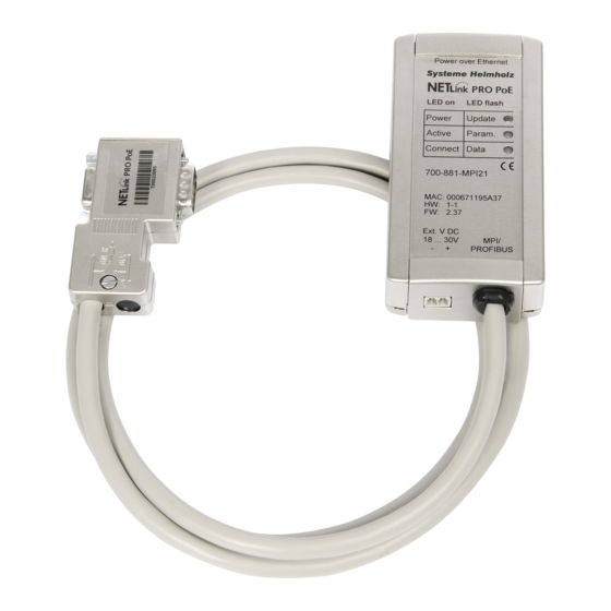
3.3.1 LEDs on the RJ45 network jack (all NETLink ® versions) The two LEDs which are located on each RJ45 female connector indicate by their status the current state of the TCP network: Lights or blinks only the yellow LED, then the LINK LED (green) ACTIVE LED (yellow) respective port is set to 10... - Page 14 LEDs and connectors on the NETLink ® PRO PoE: ® The NETLink WLAN has two extra LEDs on the top of the case, which indicate the operating status of the wireless connection: DIAG LED (yellow) ACTIVE LED (green) Status Description Status Description No Errors (WLAN)
-
Page 15: Led-Displays On The Netlink ® Pro Compact
• label with QR codes and relevant download links 3.5 Accessories 3.5.1 Manuals The current version is available for download at www.helmholz.de. 3.5.2 Software With the help of our freely available diagnostics and update soft- ware SHTools, you can, for example, carry out firmware updates yourself. -
Page 16: Wlan Antenna And Antenna Cable
Input: AC 100-240 V /Output: DC 24 V You can find additional technical data at www.helmholz.de Active PROFIBUS plug cable 3m 700-901-4BD00 3.5.4 WLAN antenna and antenna cable 2,4 GHz 5 dBi magnetic base antenna (With 1m cable) 700-889-ANT01 2,4 GHz 8 dBi Omni antenna... -
Page 17: Installation Of The Driver Software
Installation under Windows 98/ME/NT operating systems is possible but is not supported by the technical support team of Helmholz GmbH & Co.KG. Please pay attention to the require- ments of the Simatic package used. A functioning network link using TCP/IP must have been set up on the PCs that are used. -
Page 18: Adding The Interface To The Pg/Pc Interface
When installing the program on Windows 7 operating systems, make sure to not only log in with the Administrator account, but to also run the program setup file using the “Run as administra- tor” option! For more detailed information, please refer to the relevant NET- Link Quick Start Guide. - Page 19 This opens the ‘Install/uninstall interface’ dialog box. After you have selected the entry ‘NETLink-S7-NET PRO family’ from the left-hand list, click the ‘Install-->’ button. The ‘NETLink-S7-NET PRO’ has now been included in the selec- tion list so that it is available for selection in future. The access path in the ‘Set PG/PC Interface’...
-
Page 20: Selecting The Required Interface Parameterization
4.3.2 Selecting the required interface parameterization The selection list for the interface parameter sets now contains an ® additional three items for NETLink PRO Family. All relevant settings of a NETLink-S7-NET driver can be made via the "Properties" access field. With the button ‘Diagnostics...’ it is possible to show the nodes connected to the bus and the parame- ters the bus is working with. -
Page 21: Configuration Via The Netlink-S7-Net Driver
Configuration via the NETLink-S7-NET Driver Once a NETLink ® PRO Family has been selected in the ‘Set PG/PC Interface’ window, it is possible to specify this access path more precisely with the ‘Properties…’ button. With the functionality behind the button ‘Diagnostics...,’ which is ®... -
Page 22: Mpi
S7-NET driver in various automation systems, possibly with dif- ferent transmission speeds. This auto-baud function is only supported when the 'Cyclical dis- tribution of the bus parameters' is activated in the involved automa- tion system. This function is not available in S7-200 systems in general. -
Page 23: Profibus Configuration
Some older Siemens CPUs do not support the auto baud function on the MPI. PPI systems do not usually support this function ei- ther. In such cases, the network-related parameters should be adapted manually. Enabling the “Automat- ic transmission rate detection”... - Page 24 In this case, the timeout value should be increased correspond- ingly. Profile: • Under PROFIBUS, there are usually the profiles DP, Standard und User defined. • The profile must be selected that is already used in the programmable controller. Bus parameters: •...
- Page 25 In this way you avoid the laborious steps involved in manual configuration, and most importantly ensure that profibus ® networks work with many participants of the NETLink with the correct profibus parameters. Under PROFIBUS, please note that the auto baud function works best if the ‘Cyclic distribution of the bus parameters’...
-
Page 26: Ppi Configuration
5.1.3 PPI configuration Generally, the same thing applies under PPI as for the MPI con- figuration. However, it should be noted that passive participants never transmit the Profibus parameters, and that it is thus not possible to "automatically" determine the bus parameters. Normally the baud rate cannot be detected auto- matically at PPI systems. -
Page 27: Creating A Station
The ensuing reset would interrupt the NETLink ® link The password query must be answered correctly and confirmed with OK. • All NETLink ® Gateways be protected against unauthorized reparameterization via a password. If an attempt is made to save a parameter set with an incorrect password, the following messages is displayed: The default password is ‘admin.’... - Page 28 Internet tele servicing to networks outside of the LAN should al- ways be realized through secured and encoded procedures, such as VPN! To this purpose, the Helmholz GmbH offers appropriate router hardware. ‘OK’ stores this station, which can now be used.
-
Page 29: Setting Tcp Parameters
® If you do not want the name that is stored in the NETLink to be the same as the station name, you can overwrite the station name (e.g. replacing the name ‘Helmholz_test’ with the name ‘Workshop’ in the example below). This completes parameterization of the driver. -
Page 30: Operation Without The Dhcp
The ‘Parameterize NETLink …’ button takes you to a new input form that already contains the current parameters of the NET- ® Link If no NETLink ® Gateway can be accessed via the stated IP address, the following message will appear: This message can have two causes: •... -
Page 31: Dhcp
5.2.4 DHCP To have the NETLink ® receive its IP parameters automatically via DHCP, set a checkmark in the field ‘Get IP address automatically (DHCP).’ This then enables the ‘DHCP Timeout (s)’ input field. Enter the ® maximum waiting time here. If the NETLink Gateway does not receive any parameters from the DHCP server within this time, it will use the stored static parameters to ensure that the device is... -
Page 32: Options Of The Driver
A password that you have already set can be changed here. The configuration of the NETLink® can only be changed with the help of the password.This applies to parameterization both via the driver and via the web interface. ® Clicking the ‘Save in NETLink ’... -
Page 33: Diagnostics
Diagnostics For rudimentary diagnostics of the connected bus two sub func- tions are available: • Display bus nodes • Display bus parameters Before the diagnostics functionality is used, a valid station must be created and a plausible bus configuration set. 5.4.1 Bus members A list of all available nodes at the bus will be generated by clicking... - Page 34 It is recommended to enable auto baud functionality at MPI and PROFIBUS. NETLink ® Ethernet Products...
-
Page 35: The Tool: 'Netlink
NETLink both via the integrated web interface (see chap- ter 7.3) and with the configuration tool. The tool is accessible under ‘Start/Programs/Helmholz/NETLink-S7- NET/NETLink PRO Family Configuration’ after the NETLink-S7-NET driver has been installed. After this program has been called, the network will be searched ®... -
Page 36: Possibilities Of The Web Interface
Possibilities of the Web Interface If it has not been deactivated by the user, the web interface of all NETLink ® Gateways can be opened with any standard browser All NETLink ® devices has (tested with Firefox and Chrome). the IP address 192.168.4.49 on delivery The web interface is intended to support the user intuitively with from the factory. -
Page 37: Status Page
Status Page The status page, accessible via a link on the home page, provides the user with information without allowing unauthorized recon- ® figuration of a NETLink The page provides general information: Every submenu • firmware version, number of possible connections, etc.), and features a Help button that can be specific information (baud rate, active stations, DHCP status,... -
Page 38: Security Page
Security page The security page serves as a configuration interface that allows users to set up access restrictions. After the security query (see 7.4) has been correctly answered, the user has write-access to all parameters that are implemented for Every submenu features TCP security etc. -
Page 39: Observing Variables
Observing variables In addition to the “Observing Variables” function in the Simatic engineering tools, all NETLink ® Gateways also provides this function via the web interface. The operating menu can be accessed via the ‘Observe Variables’ link. A RFC 1006 communication channel is assigned for these functions. -
Page 40: Netlink ® Wlan In The Ad Hoc Mode
communication. The infrastructure mode that has to consist of at least one WLAN end device and an AP is also called BSS. Comparable to a mobile network the AP establishes a radio cell ® that is spatially restricted. WLAN end devices such as NETLink need to log on to this radio cell and authenticate to it. - Page 41 1. Step: The WLAN adapter has recognized the wireless networks in operating distance. 2. Step: This screen appears when you open the ‘Wireless Networks’ manager by clicking the WLAN symbol. ® 3. Step: Now select the NETLink WLAN, here ‘NL Andy’, that you wish to connect to.
- Page 42 The ‘Connect anyway’ button will only appear if no encoding is set in NETLink ® WLAN. ® 5. Step: The connection to NETLink WLAN is now successfully es- tablished, and it can be implemented e.g. via the PG/PC interface parameterization. ®...
- Page 43 2. Step: This screen appears when you open the ‘Wireless Networks’ manager by clicking the WLAN symbol. ® At this time it is assumed that NETLink WLAN is configured similar to the configuration shown on the following screen and that it is accessible via WLAN. Keep in mind to enter 26 characters in the box for the encoding key when using WEP 128 bit.
- Page 44 Furthermore the WLAN connection in this example has to be configurable via the Windows WLAN assistant or via another producer. 3. Step: Now select the NETLink ® WLAN, here ‘NL Andy’, that you wish to connect to and click the ‘Connect’ button. 4.
- Page 45 6. Step: Afterwards the following screen is shown. The connection is now ® properly established, and NETLink WLAN can now be used e.g. as programming adapter. If a wrong key is entered the PC will establish a connec- tion anyway. However, ®...
-
Page 46: Rfc1006-Function (S7-Tcp/Ip)
• WinCC flexible 2005/2007/2008 (Siemens AG) • ZenOn V6.2 (COPA-DATA) • PROCON-Win V3.2 (GTI Control) • S7-OPC Server, V3.1 and higher (Helmholz GmbH) • AGLink V4.0 (DELTALOGIC Automatisierungstechnik GmbH) • INAT-OPC-Server (INAT GmbH) • WinCE 5.0 Terminal TP21AS (Sütron Electronic GmbH) •... - Page 47 Rack * 32 + Slot = Address. For more information, please refer to Section 10 (Troubleshoot- ing). Helmholz GmbH has additional documents with example appli- cations for SCADA, HMI, and OPC available (see Section 11.3ff). NETLink ®...
-
Page 48: Bus Parameters In Single Master Operation
Bus Parameters in Single Master Operation ® If the NETLink Gateway is connected to a bus system on which no other master is active, the NETLink ® generates the token itself. This feature can be enabled on the web interface under “Basic Configuration.”... -
Page 49: Addressing With Routing Over Rfc
• Max. Tsdr This value is always ‘400’ for MPI – whatever the baud rate. For PROFIBUS the appropriate value should be read from the PROFIBUS project. • Min. Tsdr This value is always ‘20’ for MPI – whatever the baud rate. For PROFIBUS the appropriate value should be read from the PROFIBUS project. -
Page 50: Rfc Multicomputing With Tsap
9.2.1 RFC Multicomputing with TSAP This function makes it possible to communicate with more than one CPU on a rack ( multicomputing) in S7-400 systems with- out any need for the additional CPUs to be connected to the same PROFIBUS cable. For this to be possible, direct communications take place with on- ly one single configured station (CPU address 49 in this example). - Page 51 For this to be possible, direct communications only take place with one single configured station (CP address). This station then forwards data packets to the desired rack/slot. If you use this mode, the following settings must be configured on the web interface configuration page: •...
-
Page 52: Troubleshooting
Troubleshooting Q: I don’t know the IP address of my computer. A: Enter the command ‘ipconfig’ after the prompt to show the configuration of the Ethernet interfaces of your computer. Q: My computer has a firewall. Which ports must I release? A: The NETLink-S7-NET driver communicates with the NETLink ®... - Page 53 Please also enter the command PING <IP address> at the DOS prompt to check whether the NETLink ® Gateway can also be accessed physically via the network. Q: The setting dialog boxes are not appearing in the Simatic Man- ager: A: Please note that after initial installation the NETLink-S7-NET driver must be added to the PG/PC interfaces interfaces (except with Windows 7 operating systems).
- Page 54 A: The default settings of the system parameters in register SI- MATIC S7 for Cycle Formation, Sign-of-Life Monitoring and CPU-Stop Monitoring must be deactivated. Q: How can I specify the target station(s) for RFC 1006 communi- cations in WinCC by using the Rack/Slot fields? A: Since the RFC protocol does not have a default entry for speci- fying the PROFIBUS/MPI address of a target station (PLC), you will have to use the 2 byte-long TSAP field.
- Page 55 Q: What must I observe when calling your technical support? A: Please have all relevant data of your system constellation with the connected stations, program modules and status messages at hand when you contact technical support from Helmholz GmbH & Co.KG. NETLink ®...
-
Page 56: Appendix
Appendix 11.1 General technical Data Operating voltage 24 V DC ±25 % Ethernet interface 10 Base-T / 100 Base-TX, Auto - (MDI)X Ethernet connection RJ45 socket Ethernet transmission rate 10 Mbps and 100 Mbps MPI/PROFIBUS interface RS485, electrically isolated 9.6 Kbps; 19.2 kbps 45.45 kbps 93.75 kbps... - Page 57 11.1.3 Technical Data NETLink ® PRO Compact Dimensions in mm (LxWxH) 64 x40 x 17 Weight Approx. 110 g Current consumption 200 mA 2 LEDs, including 1 three-color LED, for general Displays status information 11.2 Pin assignments 11.2.1 MPI/PROFIBUS interface pin assignments Connector Signal Meaning...
- Page 58 11.3 Further documentation In addition to this manual, you will always find further information or new and revised versions at: www.helmholz.de. Selection as of 08/2011: • Extended NETLink ® functions - Project-specific interface • Communication with OPC, SCADA, HMI - Application exam- ples with RFC 1006 •...
- Page 59 11.3.3 Address conversion table The following table is a parameterization aid for fining the correct setting for Routing over RFC or for remote TSAP in addressed mode. Please note that the rack and slot together fill only one byte which is divided as follows: •...
- Page 60 Glossary These are explanations of the most important technical terms and abbreviations from the manual: 128 Bit: Means in this manual the encoding of WLAN data using a code of 128 bit. That adds to a total of 3*10^38 different keys 64 Bit: Means in this manual the encoding of WLAN data using a code of 128 bit.
- Page 61 IP addresses into plain text addresses Domain The domain is the name of an Internet page. It consists of the name and an name extension. The domain of Helmholz is: www.helmholz.de Encryp- Encryption is the general term for encoding procedures tion: Endspan The Endspan device is also usually a switch which, as PSE, has the PoE functionality.
- Page 62 hexadecimal notation. Example: 08-FF-FA-9C-ED-5A Master Is an active station that is permitted to transmit data and request data from other stations, when it holds the token MDI / Makes it possible to identify if a cross over or a straight cable is connected and MDI-X configures the port accordingly.
- Page 63 warding Point-to-point interface, interface with S7-200 systems with a maximum baud rate of 187.5 kbps PROFIBUS Process Field Bus is the protocol that is used mainly for automation, e.g. for the S7-300 and S7-400 systems with a maximum baud rate of 12 Mbps Profinet Standard for industrial Ethernet in automation.
- Page 64 WLAN party to log on the access point. Slave A station that is only permitted to exchange data with the master if requested to do so by the latter. SMA: Subminiature. A microwave plug or a microwave socket that is used for HF and microwave techniques as well as in WLAN due to its robustness.
- Page 65 Virtual Private Network. Logical links, called tunnels, are established iva existing unsecured networks. The end points of these links (“tunnel ends”) and the devices behind them can be thought of as a separate, logical network. A very high level of security against tapping and tampering can be achieved if data transmission via tunnels is encrypted and the stations in this logical network first authenticate each other.
Need help?
Do you have a question about the NETLink 700-881-MPI21 and is the answer not in the manual?
Questions and answers